EP0633650A1 - Moteur électrique synchrone - Google Patents
Moteur électrique synchrone Download PDFInfo
- Publication number
- EP0633650A1 EP0633650A1 EP94109686A EP94109686A EP0633650A1 EP 0633650 A1 EP0633650 A1 EP 0633650A1 EP 94109686 A EP94109686 A EP 94109686A EP 94109686 A EP94109686 A EP 94109686A EP 0633650 A1 EP0633650 A1 EP 0633650A1
- Authority
- EP
- European Patent Office
- Prior art keywords
- pump
- electric motor
- casing
- pump body
- openings
- Prior art date
- Legal status (The legal status is an assumption and is not a legal conclusion. Google has not performed a legal analysis and makes no representation as to the accuracy of the status listed.)
- Withdrawn
Links
Images

Classifications
-
- F—MECHANICAL ENGINEERING; LIGHTING; HEATING; WEAPONS; BLASTING
- F04—POSITIVE - DISPLACEMENT MACHINES FOR LIQUIDS; PUMPS FOR LIQUIDS OR ELASTIC FLUIDS
- F04D—NON-POSITIVE-DISPLACEMENT PUMPS
- F04D13/00—Pumping installations or systems
- F04D13/02—Units comprising pumps and their driving means
- F04D13/06—Units comprising pumps and their driving means the pump being electrically driven
-
- F—MECHANICAL ENGINEERING; LIGHTING; HEATING; WEAPONS; BLASTING
- F04—POSITIVE - DISPLACEMENT MACHINES FOR LIQUIDS; PUMPS FOR LIQUIDS OR ELASTIC FLUIDS
- F04D—NON-POSITIVE-DISPLACEMENT PUMPS
- F04D13/00—Pumping installations or systems
- F04D13/02—Units comprising pumps and their driving means
- F04D13/06—Units comprising pumps and their driving means the pump being electrically driven
- F04D13/08—Units comprising pumps and their driving means the pump being electrically driven for submerged use
- F04D13/086—Units comprising pumps and their driving means the pump being electrically driven for submerged use the pump and drive motor are both submerged
-
- F—MECHANICAL ENGINEERING; LIGHTING; HEATING; WEAPONS; BLASTING
- F04—POSITIVE - DISPLACEMENT MACHINES FOR LIQUIDS; PUMPS FOR LIQUIDS OR ELASTIC FLUIDS
- F04D—NON-POSITIVE-DISPLACEMENT PUMPS
- F04D15/00—Control, e.g. regulation, of pumps, pumping installations or systems
- F04D15/0005—Control, e.g. regulation, of pumps, pumping installations or systems by using valves
- F04D15/0022—Control, e.g. regulation, of pumps, pumping installations or systems by using valves throttling valves or valves varying the pump inlet opening or the outlet opening
-
- H—ELECTRICITY
- H02—GENERATION; CONVERSION OR DISTRIBUTION OF ELECTRIC POWER
- H02K—DYNAMO-ELECTRIC MACHINES
- H02K21/00—Synchronous motors having permanent magnets; Synchronous generators having permanent magnets
- H02K21/12—Synchronous motors having permanent magnets; Synchronous generators having permanent magnets with stationary armatures and rotating magnets
- H02K21/14—Synchronous motors having permanent magnets; Synchronous generators having permanent magnets with stationary armatures and rotating magnets with magnets rotating within the armatures
- H02K21/18—Synchronous motors having permanent magnets; Synchronous generators having permanent magnets with stationary armatures and rotating magnets with magnets rotating within the armatures having horse-shoe armature cores
-
- H—ELECTRICITY
- H02—GENERATION; CONVERSION OR DISTRIBUTION OF ELECTRIC POWER
- H02K—DYNAMO-ELECTRIC MACHINES
- H02K1/00—Details of the magnetic circuit
- H02K1/06—Details of the magnetic circuit characterised by the shape, form or construction
- H02K1/12—Stationary parts of the magnetic circuit
- H02K1/14—Stator cores with salient poles
-
- H—ELECTRICITY
- H02—GENERATION; CONVERSION OR DISTRIBUTION OF ELECTRIC POWER
- H02K—DYNAMO-ELECTRIC MACHINES
- H02K5/00—Casings; Enclosures; Supports
- H02K5/04—Casings or enclosures characterised by the shape, form or construction thereof
- H02K5/12—Casings or enclosures characterised by the shape, form or construction thereof specially adapted for operating in liquid or gas
- H02K5/132—Submersible electric motors
Definitions
- the present invention relates to a synchronous electric motor for small tools and devices such as for example micro-pumps for aquariums, which includes a central supporting body for an electric coil and two substantially laminar stator poles between which a rotor with high magnetic retentivity is rotatably inserted.
- the invention equally relates to a series of submersible centrifugal micro-pumps driven by these motors.
- stator or fixed part, which supports two coils, or electric windings, for generating the magnetic flux
- rotor generally of the permanent-magnet type
- the stator is generally formed by a pack of ferromagnetic laminations which are substantially U-shaped, from a top plan view.
- the coils are respectively constituted by turns of electric wire, wound on each one of the two parallel portions of the pack of laminations.
- the free ends of the portions form stator poles between which the rotor is rotatably inserted so that its rotation axis is substantially at right angles to the axis of the turns of the coils.
- the turns of the coils are approximately square and the mean turn length is greater than the circumference inscribed in the mean turn, thereby increasing the mean diameter of the stator.
- a drawback of conventional synchronous electric motors is their relatively large bulk which prevents their use in devices which, due to functional or aesthetic reasons, must have small dimensions and/or slender shapes, such as for example submersible micro-pumps which are suitable for insertion in small openings of jerry-cans and the like.
- the aim of the invention is to eliminate the drawbacks described above by providing a synchronous electric motor particularly for small-size user devices, such as for example micro-pumps for ornamental aquariums, that has an extremely small bulk and a predominantly axial extension.
- An object of the invention is to provide a synchronous electric motor which, power for power, is much lighter than known motors.
- Another object is to provide a motor which is constituted by a minimum number of components, can be easily assembled and has a low cost.
- Another object is to provide a submersible micro-pump, particularly for aquariums, which has a slender shape with a predominantly axial extension and is characterized by extremely low weight, low cost, and constructive simplicity.
- a synchronous electric motor particularly for small user devices, comprising a rotor arranged in a stator unit having a predominantly axial extension, characterized in that said stator unit comprises two substantially laminar polar bodies which are appropriately shaped and are fixed to an intermediate body adapted to support said stator winding.
- the stator winding is constituted by a single coil that has turns which have a substantially circular plan shape.
- the portion of the surface of the laminar polar bodies that faces the rotor is shaped so as to substantially follow the curvature of the rotor. Furthermore, the polar bodies have multiple longitudinal slits adapted to reduce counterelectromotive forces.
- a submersible centrifugal micro-pump is characterized in that it is driven by a synchronous electric motor according to the invention and in that it includes a pump body that has an approximately cylindrical shape with an inlet and an outlet and can be coupled coaxially and rotatably to one end of a cylindrical casing that contains the motor, a flow-rate adjustment means being built into the pump body and being meant to cooperate with a corresponding means provided on the casing.
- the flow-rate adjustment means can be constituted by multiple first openings formed on the pump body proximate to the portion for coupling to the casing, on which there are second openings that can be aligned with respect to the first ones by means of the relative rotation of the casing with respect to the pump body.
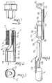
- the motor according to the invention includes a stator unit, or stator, 2 that has a substantially axial extension, having an axis L.
- the stator 2 is generically formed by two substantially laminar polar bodies 3 and 4 which are connected to an intermediate part 5 that supports a winding or electric coil 6.
- the stator can be coupled to a rotor 7 which has a substantially longitudinal rotation axis.
- the first polar body 3 is formed with a strip of metal plate that has an elongated shape, and a thickness of 1 to 3 mm.
- the metal strip includes a longitudinal portion 8 which, in a transverse cross-section, has substantially the shape of a circular arc whose diameter is slightly larger than the diameter of the rotor 7.
- the longitudinal portion is connected, at one end 9, to a flat transverse portion 10 which is approximately circular and has a central hole 11.
- the second polar body 4 obtained from a strip of metal that is similar to the first one but is shaped differently, is generally formed by an open cylindrical portion 12 which is connected to an enlarged portion 13. Portion 13 is slightly axially staggered and is similar to the longitudinal portion 8 of the body 3 but is shorter.
- the intermediate part 5 is made of non-ferromagnetic material and is shaped approximately like a spool.
- the intermediate part 5 includes a cylindrical portion 14 with an axial hole 15 and two flanges 16, 16' at its ends.
- the electric coil 6, which generates the magnetic flux, is wound with substantially circular turns 17 about the cylindrical portion of the intermediate part 5 between the flanges 16, 16'.
- the transverse portion 10 of the first polar body faces one of the flanges 16 of the intermediate part 5, so as to center the respective holes 11, 15 on the axis L.
- the longitudinal portion 8 of the first polar body extends towards the opposite flange 16' of the intermediate part 5 so as to be parallel to it.
- the cylindrical portion 12 is inserted in the hole 15 of the intermediate part 5 at the end where the flange 16' is located, until the cylindrical portion protrudes from the opposite end, so that the end 18 is stably inserted in the hole 11 of the first polar body 3.
- the two polar bodies 3 and 4 are mutually connected mechanically and electrically.
- the enlarged portion 13 of the second polar body 4 is arranged longitudinally, opposite to the longitudinal portion 8 of the first polar body 3 which faces it, forming a pair of poles between which the rotor is inserted, so that its axis is substantially longitudinal and preferably coaxial to L.
- Both the longitudinal portion 8 of the first polar body 3 and the enlarged portion of the second polar body 4 have a plurality of longitudinal slits 19 which are suitable to reduce counterelectromotive forces, improving the pickup and overall efficiency of the motor 1.
- the motor 1 may have its stator 3 embedded in epoxy resins, or other dielectric material, in order to perfectly insulate the live parts.
- the above described motor can be used as a drive unit to actuate centrifugal micro-pumps, shown in Figures 5 to 7 and described in detail hereinafter.
- FIGS 5 and 6 illustrate a first embodiment of a submersible centrifugal micro-pump 20 that has a mainly axial extension with an axis A.
- the micro-pump 20 includes a pump body 21 that is approximately funnel-shaped with an inlet at the end which has the smallest diameter.
- Multiple first outlets 23 are arranged circumferentially on the portion at the end 24, which has the largest diameter, which internally forms a pressure chamber 25.
- An impeller 26 is arranged in the pressure chamber 25.
- the pump body 21 is coaxially and rotatably coupled to a cylindrical casing 27 that contains the motor 1 on the rotor axis of which the impeller 26 is keyed.
- the casing 27 is closed at one end by a lid 28 and has, at its opposite end, a portion 29 which is coaxially and rotatably coupled to the portion 24 of the pump body 21.
- the portion 29 is circumferentially provided with multiple second outlets 30 that can be aligned with respect to the first ones 23 provided on the pump body in order to vary the useful passage section of the liquid, consequently varying the flow-rate of the micro-pump.
- the user In order to adjust the flow-rate of the micro-pump 20, the user must rotate the casing 27 about its own axis with respect to the pump body 21, thus varying the useful passage section of the outgoing liquid and consequently the flow-rate of the micro-pump.
- the openings 23 of the pump body 21 are perfectly aligned and coincide with the openings 30 provided on the casing 27. In this case the maximum useful passage section is obtained.
- Both the casing and the pump body are preferably made of plastic.
- the motor inserted in the casing may be embedded beforehand in a layer of dielectric plastic material to ensure perfect insulation.
- a sealed switch 31 for the control of the micro-pump.
- Figure 7 illustrates a second embodiment of the micro-pump according to the invention, which is similar to the first one and includes a flow-rate adjustment means which is substantially equivalent to those of the first embodiment but is arranged at the inlet of the liquid.
- the pump body which has a cylindrical shape, includes multiple inlets 32 which are arranged circumferentially proximate to the base 33 and can be aligned with corresponding openings 34 provided on the casing in order to vary the useful passage section of the liquid, adjusting the flow-rate of the micro-pump.
- openings 32, 34 are aligned as in the first embodiment described above, i.e. by rotating the casing coaxially with respect to the pump body.
- the inlets 32, 34 furthermore form a grille for filtering the aspirated liquid.
- the pumped liquid flows out through a duct 35 which is formed by a longitudinal portion 36 the axis of which is substantially parallel to the axis A.
- the longitudinal portion is connected, at one end 37, to the outlet of the pump body, and at the opposite end there is an end portion 38 which is curved so as to form a part for anchoring to a side wall of a container, not shown in the figures, in which the micro-pump is immersed.
- the very small dimensions and slender shape allow to insert the micro-pump in small-diameter openings, facilitating its concealment if the pump is aesthetically undesirable.
Landscapes
- Engineering & Computer Science (AREA)
- Mechanical Engineering (AREA)
- General Engineering & Computer Science (AREA)
- Power Engineering (AREA)
- Motor Or Generator Frames (AREA)
- Structures Of Non-Positive Displacement Pumps (AREA)
- Connection Of Motors, Electrical Generators, Mechanical Devices, And The Like (AREA)
- Permanent Magnet Type Synchronous Machine (AREA)
Applications Claiming Priority (2)
| Application Number | Priority Date | Filing Date | Title |
|---|---|---|---|
| ITVI930118 | 1993-07-08 | ||
| ITVI930118A IT1271894B (it) | 1993-07-08 | 1993-07-08 | Motore elettrico sincrono particolarmente per pompe idrauliche di piccole dimensioni |
Publications (1)
| Publication Number | Publication Date |
|---|---|
| EP0633650A1 true EP0633650A1 (fr) | 1995-01-11 |
Family
ID=11425295
Family Applications (1)
| Application Number | Title | Priority Date | Filing Date |
|---|---|---|---|
| EP94109686A Withdrawn EP0633650A1 (fr) | 1993-07-08 | 1994-06-23 | Moteur électrique synchrone |
Country Status (3)
| Country | Link |
|---|---|
| EP (1) | EP0633650A1 (fr) |
| JP (1) | JPH07170703A (fr) |
| IT (1) | IT1271894B (fr) |
Citations (4)
| Publication number | Priority date | Publication date | Assignee | Title |
|---|---|---|---|---|
| FR936395A (fr) * | 1945-12-04 | 1948-07-19 | Raleigh Cycle Company Ltd | Machine magnéto-électrique utilisable notamment comme dynamo d'éclairage pour bicyclettes |
| CH262080A (de) * | 1948-02-27 | 1949-06-15 | Ag Metallwarenfabrik | Fahrraddynamo. |
| US3551711A (en) * | 1969-01-21 | 1970-12-29 | Hermetic Coil Co Inc | Encapsulated electric motor having p-m rotor and claw tooth station |
| EP0207430A2 (fr) * | 1985-07-01 | 1987-01-07 | EASTHORPE INVESTMENTS Ltd. | Pompe centrifuge |
-
1993
- 1993-07-08 IT ITVI930118A patent/IT1271894B/it active IP Right Grant
-
1994
- 1994-06-23 EP EP94109686A patent/EP0633650A1/fr not_active Withdrawn
- 1994-07-06 JP JP6154481A patent/JPH07170703A/ja active Pending
Patent Citations (4)
| Publication number | Priority date | Publication date | Assignee | Title |
|---|---|---|---|---|
| FR936395A (fr) * | 1945-12-04 | 1948-07-19 | Raleigh Cycle Company Ltd | Machine magnéto-électrique utilisable notamment comme dynamo d'éclairage pour bicyclettes |
| CH262080A (de) * | 1948-02-27 | 1949-06-15 | Ag Metallwarenfabrik | Fahrraddynamo. |
| US3551711A (en) * | 1969-01-21 | 1970-12-29 | Hermetic Coil Co Inc | Encapsulated electric motor having p-m rotor and claw tooth station |
| EP0207430A2 (fr) * | 1985-07-01 | 1987-01-07 | EASTHORPE INVESTMENTS Ltd. | Pompe centrifuge |
Also Published As
| Publication number | Publication date |
|---|---|
| ITVI930118A0 (it) | 1993-07-08 |
| IT1271894B (it) | 1997-06-10 |
| ITVI930118A1 (it) | 1995-01-08 |
| JPH07170703A (ja) | 1995-07-04 |
Similar Documents
| Publication | Publication Date | Title |
|---|---|---|
| EP0604762B1 (fr) | Moteur synchrone électrique surtout pour pompes à moteur submersible et pour moto-pompes électriques | |
| JP7317006B2 (ja) | 血液ポンプ | |
| US4683388A (en) | Compound induction electric rotating machine | |
| EP1760859B1 (fr) | Moteur synchrone monophasé avec un rotor à aimant permanent et stator améliore, en particulier pour pompes de lavage des machines à laver et machines domestiques pareils | |
| CN102577031B (zh) | 双极轴向挤压永磁体电动机 | |
| CN104578668B (zh) | 小型高频振动装置 | |
| US6393208B1 (en) | Compressor with integrated impeller and motor | |
| JPH11506182A (ja) | 低流量ポンプ | |
| EP2006976B1 (fr) | Moteur électrique synchrone biphasé | |
| WO2005034312A3 (fr) | Pompe rotative a support lcr electromagnetique | |
| CN110311527A (zh) | 轴向磁通转子和轴向磁通电机 | |
| RU2287888C2 (ru) | Способ изготовления статора бесщеточного электродвигателя постоянного тока и статор бесщеточного электродвигателя постоянного тока, изготовленный указанным способом | |
| CN110311490A (zh) | 制造轴向磁通转子的方法和相关的轴向磁通转子 | |
| CN212572340U (zh) | 无刷电机、定子和槽防护件 | |
| JPWO2002027898A1 (ja) | リニアアクチュエータ | |
| CN103648538A (zh) | 血泵 | |
| CN110429783B (zh) | 永磁直流无刷电机结构 | |
| US6106324A (en) | Programmable termination strip for electric motor | |
| JPH05501046A (ja) | 電動機 | |
| EP2019476A2 (fr) | Moteurs électriques | |
| JP3636454B2 (ja) | 往復動式モータの固定子 | |
| CN204349756U (zh) | 小型高频振动装置 | |
| EP2025944B1 (fr) | Moteur synchrone monophasé pour machines domestiques | |
| WO2014142999A1 (fr) | Machine électrique à flux axial dipolaire | |
| KR101899508B1 (ko) | 개량된 로터를 갖는 스위치드 릴럭턴스 모터 |
Legal Events
| Date | Code | Title | Description |
|---|---|---|---|
| PUAI | Public reference made under article 153(3) epc to a published international application that has entered the european phase |
Free format text: ORIGINAL CODE: 0009012 |
|
| AK | Designated contracting states |
Kind code of ref document: A1 Designated state(s): DE FR GB IT |
|
| STAA | Information on the status of an ep patent application or granted ep patent |
Free format text: STATUS: THE APPLICATION IS DEEMED TO BE WITHDRAWN |
|
| 18D | Application deemed to be withdrawn |
Effective date: 19950712 |