EP0633807B1 - Separator device - Google Patents
Separator device Download PDFInfo
- Publication number
- EP0633807B1 EP0633807B1 EP93904196A EP93904196A EP0633807B1 EP 0633807 B1 EP0633807 B1 EP 0633807B1 EP 93904196 A EP93904196 A EP 93904196A EP 93904196 A EP93904196 A EP 93904196A EP 0633807 B1 EP0633807 B1 EP 0633807B1
- Authority
- EP
- European Patent Office
- Prior art keywords
- drum
- solid material
- spiral
- casing
- journal
- Prior art date
- Legal status (The legal status is an assumption and is not a legal conclusion. Google has not performed a legal analysis and makes no representation as to the accuracy of the status listed.)
- Expired - Lifetime
Links
Images


Classifications
-
- B—PERFORMING OPERATIONS; TRANSPORTING
- B01—PHYSICAL OR CHEMICAL PROCESSES OR APPARATUS IN GENERAL
- B01D—SEPARATION
- B01D33/00—Filters with filtering elements which move during the filtering operation
- B01D33/06—Filters with filtering elements which move during the filtering operation with rotary cylindrical filtering surfaces, e.g. hollow drums
- B01D33/11—Filters with filtering elements which move during the filtering operation with rotary cylindrical filtering surfaces, e.g. hollow drums arranged for outward flow filtration
-
- B—PERFORMING OPERATIONS; TRANSPORTING
- B01—PHYSICAL OR CHEMICAL PROCESSES OR APPARATUS IN GENERAL
- B01D—SEPARATION
- B01D33/00—Filters with filtering elements which move during the filtering operation
- B01D33/70—Filters with filtering elements which move during the filtering operation having feed or discharge devices
- B01D33/72—Filters with filtering elements which move during the filtering operation having feed or discharge devices for feeding
- B01D33/722—Filters with filtering elements which move during the filtering operation having feed or discharge devices for feeding containing fixed liquid displacement elements or cores
-
- B—PERFORMING OPERATIONS; TRANSPORTING
- B01—PHYSICAL OR CHEMICAL PROCESSES OR APPARATUS IN GENERAL
- B01D—SEPARATION
- B01D33/00—Filters with filtering elements which move during the filtering operation
- B01D33/80—Accessories
- B01D33/801—Driving means, shaft packing systems or the like
Definitions
- This invention relates to a separator device for separating solid material from liquid.
- PCT/SE87/00504 shows a rotatable drum sieve in which a liquids/solids mixture is fed to a pipe which is fixed to and extends internally within a rotatably driven horizontal drum.
- the pipe is fixed to the drum by a feed screw, and supply openings are provided along the pipe to feed mixture from the pipe into a drum space.
- Liquid drains away through sieve openings in the drum, whilst sieved solids material is moved along the drum by the feed screw, lifted back into a separated end section of the pipe and discharged therefrom by means of a discharge screw. Excess unsieved material is fed via a spillway for further sieving.
- An object of the invention is to provide such a separator device in an improved manner.
- a separator for separating solid material from liquid comprises a casing, a liquid material outlet from the casing, a solid material outlet, the liquid material outlet being separate from the solid material outlet, a drum within the casing, the drum having first and second ends, an outlet, and an apertured surface for liquid to flow out of the drum, an inlet member for the supply of a mixture of said solid material and said liquid into the drum, the inlet member being concentric with said drum axis and being rotatable with said drum, a feed member for the supply of said mixture of said solid material and said liquid, the feed member being fixed relative to the inlet member and concentric therewith, a rotary seal between the inlet member and the feed member, a first journal at said first end of the drum, a bearing outside of an end of the casing, the first journal being supported by said bearing and rotating upon rotation of said drum and inlet member, drive means at said second end of the drum for rotatably driving the drum and inlet member, spiral means within the drum for moving said solid material within the
- the drawings show a separator device which is particularly intended for use with sewage and the like and is generally known as a screen.
- the screen of Figures 1 to 3 has an outer casing 10 made up of an upper removable cover part 11 which is fixed to longitudinal side parts 12, 13 respectively.
- the two side parts connect together at the bottom of the screen, the casing being closed along most of its lower part but having a liquid outlet 14 at one end and a solid material outlet 15 at its opposite end.
- the casing slopes downwardly from the outlet 15 to the outlet 14, 50 that, as will be described, separated liquid drains to said outlet 14 where it is removed from the screen.
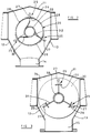
- the transverse cross-sectional shape of the casing can be seen from Figures 2 and 3.
- a composite end plate assembly 16 which carries a support housing 17. This has a central opening in which is received radial and thrust bearings 18 which carry a journal 19 which extends from an end of a drum 20, which is disposed in the casing 10 as will be described.
- the journal 19 extends from the housing 17 away from the casing to a position where it is connected via a flexible coupling 21 to a drive unit 22 for rotating the journal 19 and thus the drum 20.
- the drum 20 has its central axis at the same inclination as the casing 10 previously described. At its end where it is driven, the drum is closed by a circular end plate 23, from which the journal 19 extends. Centrally connected inwards of this plate 23 is a cylindrical ring 24. Connected to the ring 24 and extending longitudinally therefrom in an inwards direction away from the plate 23 are three rigid drum body members 25, each member 25 extending parallel to the axis of the drum defined by the centre of the plate 23, the members 25 being equi-angularly spaced around the ring 24 and thus the drum itself. As can be seen from Figure 2, each member 25 comprises a short arcuate portion 26 of substantially the same radius as the ring 24 from which perpendicularly extends a rib part 27.
- each member 25 Extending longitudinally from the ring 24 between the members 25 respectively are three mesh panels 28, shown in Figure 2. These mesh panels are each of arcuate form and together with the arcuate portions 26 of the members 25 form the circular drum 20 which has a diameter substantially corresponding to that of the ring 24.
- the mesh panels 28 extend to a further cylindrical ring 29 which is axially positioned where the closed underneath of the casing 10 opens to form the solid material outlet 15.
- the three mesh panels 28 terminate at the ring 29, the three members 25 extend beyond said ring 29, where an outlet from the drum is defined, to a further circular end plate 30 similar to the end plate 23.
- each member 25 has a radially inward extension part 31 connected to the further end plate 30.
- the end plate 30 is spaced a short distance inwards of the end of the casing 10 remote from the support housing 17.
- spirals 32 are equi-angularly spaced spirals 32, each of which is attached at its one end to the plate 23 and at its outer periphery, along its length to an arcuate portion 26 of the drum, as shown in Figures 1 and 2.
- the spirals terminate at the end of ring 29.
- the spiral pitch varies along the length of the drum, for example as shown in Figure 1.
- a central inlet member in the form of a tube 33. As will be described, this extends from outside of the end of the casing adjacent the end plate 30, and within the drum this tube terminates short of the end plate 23.
- this tube 33 is connected at its outer periphery to the respective inner peripheries of the three spirals 32.
- the spirals are fixed to and thus supported along part of their respective lengths by the part of the tube 33 within the drum defined between the rings 24 and 29 and thus this central tube 33 rotates with the drum, in use.
- the spirals, being supported at both their inner and outer peripheries respectively, are thus held securely in position in the drum.
- the end of the casing adjacent the outlet 15 is closed by an end plate 34.
- a journal 35 in the form of an end of the drum, in that this journal is welded to the further end plate 30 of the drum, to which end plate the tube 33 is also secured, this tube 33 extending through the length of the journal 35 to terminate flush therewith at a position spaced outwardly of the end plate 34 of the casing.
- a cylindrical support housing 36 Welded to the outside of the end plate 34 is a cylindrical support housing 36.
- This housing 36 has a central machined bore 37 in which is received a radial bearing 38 which carries the journal 35 at this non-driven end of the drum.
- the end of the tube 33 has a rotary seal 39 and the flush ends of the tube 33 and journal 35 respectively are received in an end recess 40 of the housing 36, which recess is closed by a plate 41.
- This plate carries a non-rotatable feed member in the form of a feed tube 42 which is concentric with the tube 33 and extends into it. In this example it terminates at a position just where the tube 33 enters the further ring 29, although its extent into the tube 33 can be smaller or greater.
- the use of the tube 42 is convenient in that it provides a positive feed of the mixture into the tube 33 and provides a non-rotatable, i.e. fixed, flange 43 for connection to a conventional supply pipe.
- the bearings for the journals 19 and 35 respectively are in-line, thus being relatively easy accurately to produce, and by producing the journals accurately during manufacture of the drum, previous rotation problems with prior art screens are overcome. Assisting in this improved drum rotation is the positioning of the bearing arrangement at at least the non-driven end of the screen at a journal projecting from the drum and casing.
- operation of the drive unit 22 causes rotation of the drum 20 via the flexible coupling 21, with rotation of the drum also causing rotation therewith of the central tube 33, this rotation taking place at the non-driven end of the drum by way of the drum journal rotating in the bearing 38 in the support housing 36.
- the mixture of solid material and liquid to be separated is fed to the fixed feed tube 42, and therefrom the mixture passes into the tube 33, from where it is fed into the drum 20.
- the drum and tube 33 rotate the liquid part of the mixture drains out through the mesh panels into the housing, where it drains downwardly to leave the casing through the outlet 14, to be collected or disposed of as appropriate.
- the bearings at both ends of the rotatable drum are outside of the casing 10 and, particularly at the non-driven end of the drum the bearing arrangement does not come into contact with the mixture being separated, as is the case with prior art arrangements where the non-driven end of the drum is supported on a roller within the casing. Not only is such an arrangement detrimental to the roller but it also prevents flow of material to the solid outlet to some degree.
- a further advantage of having the bearing 38 outside of the casing is that, as mentioned, it is easier accurately to produce the journal and support housing bore by machining after initial fabrication. Where, with prior art arrangements, one or more rollers have been provided within the casing to support the drum it is difficult to ensure that the required surfaces are geometrically accurate.
- the present arrangement enables lubrication of the bearing at the non-driven end to be undertaken much more easily than, for example, when this is within the mixture flow within the casing.
- the embodiment of the screen described is particularly advantageous where it is of a large size as compared to presently known screens, in that although of longer length it is still stable and robust due to the fact that the central feed tube and the spirals are connected together and also both rigidly connected to the drum, the drum in this sense extending to the plate 34 and having its end in the form of the outer journal 35. Although this is not an essential feature, it does strengthen the whole of such a longer screen. Alternatively not all the spirals need be connected to the tube 33.
- FIG. 1 to 3 the screen is arranged with the liquid outlet adjacent the lower end of the downwardly sloping drum.
- Figure 4 shows a further embodiment of a screen of the invention, similar to the embodiment of Figures 1 to 3, but having its solid material outlet 44 adjacent the lower end of the downwardly sloping drum instead of at the upper end of the drum. Identical parts of this further embodiment are given the same reference numerals as used in the first embodiment described. Only one spiral of the three is shown, for clarity.
- the lower part of the casing is raised at the inner side of the outlet 44 almost up to ring 45, but then slopes downwardly away to the liquid outlet 46, to which the lower part of the casing extending from end plate 34 also slopes downwardly, the outlets 44, 46 terminating in the same horizontal plane, and effectively being substantially isolated from one another by the casing shape.
- the drive journal 19 extends a substantial distance into the drum and the spirals, which all extend, in this embodiment, for the whole length of the drum, are fixed at their respective inner peripheries to the journal 19. As before, the spirals are fixed at their respective outer peripheries to the arcuate portions along their length.
- the central tube 33 is shortened so that it extends only a short distance into the drum, and similarly the fixed feed tube 42 is also shortened, terminating substantially at the plane of end plate 30.
- the tube 33 is fixed to at least one, and preferably all, of the spirals, despite its reduced length, although this support of the spirals could be omitted, full inner peripheral support being taken by the journal 19 alone.
- the separation process is similar to that with the screen of Figures 1 to 3 for solid material, in that on passing out of feed tube 33 it is transported by the spirals along the drum.
- the screen of Figure 4 the material is carried downwardly in the drum to the lower end thereof where the members 25 and spirals 32 are still present but where the absence of the panels 28 beyond ring 45 allows the material to fall from through the drum outlet to the solid material outlet 44.
- Liquid flowing into the drum from feed tube 42 and tube 33 can drain through the mesh panels 28 forming the drum and be guided by the inclined lower part of the casing to the liquid outlet 46.
- the mesh is relatively fine, i.e. with small openings therein, or if the amount or nature of the solid material is such that the outflow is restricted, a build-up of liquid could occur in the drum from the end plate 30 to the plane defined at the end of the journal 19 in the drum.
- the input of further liquid will cause the liquid in the drum to spill into the first 'chamber' formed beyond the end of the journal 19 by the spirals therearound, until the level of liquid in that chamber is sufficient for liquid to 'spill over', in the manner of a weir, into the next 'chamber' and so on, liquid draining through the mesh panels of these 'chambers' wherever possible.
- each spiral can be of opposite hand to its remainder to prevent jamming of solids.
- the spiral means for moving the solid material along the drum could be non-continuous. At one or both ends of the screen, outside the casing, it could be the tube 33 forming the journal received in the bearing rather than the journal being part of the drum.
Landscapes
- Chemical & Material Sciences (AREA)
- Chemical Kinetics & Catalysis (AREA)
- Centrifugal Separators (AREA)
- Filtration Of Liquid (AREA)
- Treatment Of Sludge (AREA)
Applications Claiming Priority (3)
| Application Number | Priority Date | Filing Date | Title |
|---|---|---|---|
| GB9204979 | 1992-03-06 | ||
| GB929204979A GB9204979D0 (en) | 1992-03-06 | 1992-03-06 | Separator device |
| PCT/GB1993/000312 WO1993017775A1 (en) | 1992-03-06 | 1993-02-15 | Separator device |
Publications (2)
| Publication Number | Publication Date |
|---|---|
| EP0633807A1 EP0633807A1 (en) | 1995-01-18 |
| EP0633807B1 true EP0633807B1 (en) | 1997-01-29 |
Family
ID=10711674
Family Applications (1)
| Application Number | Title | Priority Date | Filing Date |
|---|---|---|---|
| EP93904196A Expired - Lifetime EP0633807B1 (en) | 1992-03-06 | 1993-02-15 | Separator device |
Country Status (9)
| Country | Link |
|---|---|
| US (1) | US5500114A (da) |
| EP (1) | EP0633807B1 (da) |
| AU (1) | AU3507293A (da) |
| CA (1) | CA2131557A1 (da) |
| DE (1) | DE69307870T2 (da) |
| DK (1) | DK0633807T3 (da) |
| ES (1) | ES2099943T3 (da) |
| GB (1) | GB9204979D0 (da) |
| WO (1) | WO1993017775A1 (da) |
Cited By (1)
| Publication number | Priority date | Publication date | Assignee | Title |
|---|---|---|---|---|
| US10708538B2 (en) | 2016-12-16 | 2020-07-07 | Wessels Company | Air-dirt separator with coalescing baffles |
Families Citing this family (6)
| Publication number | Priority date | Publication date | Assignee | Title |
|---|---|---|---|---|
| FR2798080B1 (fr) * | 1999-09-02 | 2001-11-23 | E R M Concept Etude Et Realisa | Dispositif et procede pour deliter certaines matieres organiques contenues dans les eaux usees et pour les separer d'autres dechets |
| DE202010010908U1 (de) | 2010-07-27 | 2010-11-11 | Hidde, Axel R., Dr. Ing. | Luft- und Schmutzabscheider für die Wassertechnik |
| DE202017000909U1 (de) | 2017-02-20 | 2017-03-15 | Thomas Nispel | Schneckenförderer |
| CN108525382B (zh) * | 2018-04-26 | 2020-12-11 | 江苏跃达环保工程有限公司 | 一种污水处理用高速离心式过滤装置 |
| US20240199442A1 (en) * | 2021-04-27 | 2024-06-20 | Mizufalls Sa | Installation for treating wastewater from a toilet and sanitary unit comprising such an installation |
| FR3122193B1 (fr) * | 2021-04-27 | 2024-05-10 | Jonathan Cavalcanti | Installation de traitement des eaux usées d’un WC et ensemble sanitaire comportant une telle installation |
Family Cites Families (13)
| Publication number | Priority date | Publication date | Assignee | Title |
|---|---|---|---|---|
| US292947A (en) * | 1884-02-05 | Machine | ||
| GB411666A (en) * | 1933-05-04 | 1934-06-14 | Gerald Hillsdon Hutton | Improvements in or relating to rotary screening-apparatus |
| GB822865A (en) * | 1957-10-29 | 1959-11-04 | British Celanese | Improvements in or relating to rotary screen separators |
| US4439320A (en) * | 1976-07-07 | 1984-03-27 | Arie Blok | Solids concentrator |
| DE2718673A1 (de) * | 1977-04-27 | 1978-11-02 | Krauss Maffei Ag | Verfahren und vorrichtung zum entwaessern von schlamm |
| US4140629A (en) * | 1977-09-15 | 1979-02-20 | Martco, Inc. | Conical screen separator |
| US4248709A (en) * | 1979-09-07 | 1981-02-03 | Robert Irving | Method of filtering sewer scum and apparatus therefor |
| DK142384A (da) * | 1984-02-29 | 1985-08-30 | Schmidt & Jessen A S | Sigtekurv med mindst et roerformet og ved begge ender aabent sigtenet |
| JPH02500726A (ja) * | 1986-11-03 | 1990-03-15 | ロートシーブ アクチェボラーグ | 回転ドラム型分離装置 |
| US4755291A (en) * | 1987-01-29 | 1988-07-05 | Lee Chung Y | Filtration and washing apparatus with adjustable rotary filtration cylinder |
| GB2216031B (en) * | 1988-03-29 | 1991-10-16 | Screening & Applic Engineers L | A rotary separator |
| US4976853A (en) * | 1989-02-02 | 1990-12-11 | Lee Chung Y | Control valve means for use in a filtration apparatus for treating waste product |
| US5133860A (en) * | 1991-12-31 | 1992-07-28 | Tai Liang C | Solid and liquid separator with a liquid filter |
-
1992
- 1992-03-06 GB GB929204979A patent/GB9204979D0/en active Pending
-
1993
- 1993-02-15 DE DE69307870T patent/DE69307870T2/de not_active Expired - Fee Related
- 1993-02-15 EP EP93904196A patent/EP0633807B1/en not_active Expired - Lifetime
- 1993-02-15 DK DK93904196.8T patent/DK0633807T3/da active
- 1993-02-15 AU AU35072/93A patent/AU3507293A/en not_active Abandoned
- 1993-02-15 WO PCT/GB1993/000312 patent/WO1993017775A1/en not_active Ceased
- 1993-02-15 ES ES93904196T patent/ES2099943T3/es not_active Expired - Lifetime
- 1993-02-15 US US08/295,756 patent/US5500114A/en not_active Expired - Fee Related
- 1993-02-15 CA CA002131557A patent/CA2131557A1/en not_active Abandoned
Cited By (1)
| Publication number | Priority date | Publication date | Assignee | Title |
|---|---|---|---|---|
| US10708538B2 (en) | 2016-12-16 | 2020-07-07 | Wessels Company | Air-dirt separator with coalescing baffles |
Also Published As
| Publication number | Publication date |
|---|---|
| US5500114A (en) | 1996-03-19 |
| GB9204979D0 (en) | 1992-04-22 |
| AU3507293A (en) | 1993-10-05 |
| DE69307870D1 (de) | 1997-03-13 |
| WO1993017775A1 (en) | 1993-09-16 |
| ES2099943T3 (es) | 1997-06-01 |
| CA2131557A1 (en) | 1993-09-16 |
| DK0633807T3 (da) | 1997-08-11 |
| EP0633807A1 (en) | 1995-01-18 |
| DE69307870T2 (de) | 1997-08-07 |
Similar Documents
| Publication | Publication Date | Title |
|---|---|---|
| EP0664727B1 (en) | Wear resistant basket for scroll centrifuge | |
| CA1121740A (en) | Separation of solids from liquids by screening | |
| KR0121732B1 (ko) | 고액분리장치 | |
| JP4489343B2 (ja) | 遠心沈降分離機 | |
| US6103110A (en) | Screening apparatus for sewage | |
| EP0633807B1 (en) | Separator device | |
| US6736968B2 (en) | Horizontal scroll screen centrifuge | |
| EP0328548A1 (en) | Arrangement for an inlet and outlet in a rotating drum sieve | |
| WO1997023295A1 (en) | Decanter centrifuge | |
| US4950219A (en) | Adjustable weir structure for a decanter centrifuge | |
| US5328611A (en) | Filtering apparatus with rotatable filter drum | |
| US4298159A (en) | Solid sleeve worm centrifuge | |
| CA2001470C (en) | Solids-liquids separator | |
| JP2009045610A (ja) | ろ過装置 | |
| US5421176A (en) | Drum washer | |
| CA2109574A1 (en) | Washer | |
| US6217502B1 (en) | Centrifugal separator having a liquid filled transmission chamber | |
| US3627138A (en) | Centrifugal separator | |
| WO1997009121A1 (en) | Rotary distribution pipe assembly | |
| EP0471768B1 (en) | Continuous filter centrifuge | |
| US3327861A (en) | Strainer | |
| KR0180278B1 (ko) | 원추형 원심분리기 | |
| WO1984004293A1 (en) | A device for purification of liquid media such as waste water | |
| JP3402418B2 (ja) | 遠心濃縮機 | |
| US3829009A (en) | Solid bowl centrifugal separator |
Legal Events
| Date | Code | Title | Description |
|---|---|---|---|
| PUAI | Public reference made under article 153(3) epc to a published international application that has entered the european phase |
Free format text: ORIGINAL CODE: 0009012 |
|
| AK | Designated contracting states |
Kind code of ref document: A1 Designated state(s): BE DE DK ES FR GB IE IT NL PT SE |
|
| 17P | Request for examination filed |
Effective date: 19941206 |
|
| 17Q | First examination report despatched |
Effective date: 19950629 |
|
| GRAG | Despatch of communication of intention to grant |
Free format text: ORIGINAL CODE: EPIDOS AGRA |
|
| RAP1 | Party data changed (applicant data changed or rights of an application transferred) |
Owner name: SPIROTECH ENGINEERING LIMITED |
|
| GRAH | Despatch of communication of intention to grant a patent |
Free format text: ORIGINAL CODE: EPIDOS IGRA |
|
| GRAH | Despatch of communication of intention to grant a patent |
Free format text: ORIGINAL CODE: EPIDOS IGRA |
|
| GRAA | (expected) grant |
Free format text: ORIGINAL CODE: 0009210 |
|
| AK | Designated contracting states |
Kind code of ref document: B1 Designated state(s): BE DE DK ES FR GB IE IT NL PT SE |
|
| PG25 | Lapsed in a contracting state [announced via postgrant information from national office to epo] |
Ref country code: BE Effective date: 19970129 |
|
| ITF | It: translation for a ep patent filed | ||
| REG | Reference to a national code |
Ref country code: IE Ref legal event code: FG4D Free format text: 71853 |
|
| REF | Corresponds to: |
Ref document number: 69307870 Country of ref document: DE Date of ref document: 19970313 |
|
| ET | Fr: translation filed | ||
| REG | Reference to a national code |
Ref country code: PT Ref legal event code: SC4A Free format text: AVAILABILITY OF NATIONAL TRANSLATION Effective date: 19970131 |
|
| REG | Reference to a national code |
Ref country code: ES Ref legal event code: FG2A Ref document number: 2099943 Country of ref document: ES Kind code of ref document: T3 |
|
| REG | Reference to a national code |
Ref country code: DK Ref legal event code: T3 |
|
| PLBE | No opposition filed within time limit |
Free format text: ORIGINAL CODE: 0009261 |
|
| STAA | Information on the status of an ep patent application or granted ep patent |
Free format text: STATUS: NO OPPOSITION FILED WITHIN TIME LIMIT |
|
| 26N | No opposition filed | ||
| PGFP | Annual fee paid to national office [announced via postgrant information from national office to epo] |
Ref country code: GB Payment date: 19980206 Year of fee payment: 6 |
|
| PGFP | Annual fee paid to national office [announced via postgrant information from national office to epo] |
Ref country code: FR Payment date: 19980210 Year of fee payment: 6 |
|
| PGFP | Annual fee paid to national office [announced via postgrant information from national office to epo] |
Ref country code: DK Payment date: 19980213 Year of fee payment: 6 |
|
| PGFP | Annual fee paid to national office [announced via postgrant information from national office to epo] |
Ref country code: SE Payment date: 19980218 Year of fee payment: 6 |
|
| PGFP | Annual fee paid to national office [announced via postgrant information from national office to epo] |
Ref country code: PT Payment date: 19980220 Year of fee payment: 6 Ref country code: DE Payment date: 19980220 Year of fee payment: 6 |
|
| PGFP | Annual fee paid to national office [announced via postgrant information from national office to epo] |
Ref country code: IE Payment date: 19980224 Year of fee payment: 6 |
|
| PGFP | Annual fee paid to national office [announced via postgrant information from national office to epo] |
Ref country code: NL Payment date: 19980226 Year of fee payment: 6 Ref country code: ES Payment date: 19980226 Year of fee payment: 6 |
|
| PG25 | Lapsed in a contracting state [announced via postgrant information from national office to epo] |
Ref country code: IE Free format text: LAPSE BECAUSE OF NON-PAYMENT OF DUE FEES Effective date: 19990215 Ref country code: GB Free format text: LAPSE BECAUSE OF NON-PAYMENT OF DUE FEES Effective date: 19990215 |
|
| PG25 | Lapsed in a contracting state [announced via postgrant information from national office to epo] |
Ref country code: SE Free format text: LAPSE BECAUSE OF NON-PAYMENT OF DUE FEES Effective date: 19990216 Ref country code: ES Free format text: LAPSE BECAUSE OF NON-PAYMENT OF DUE FEES Effective date: 19990216 |
|
| PG25 | Lapsed in a contracting state [announced via postgrant information from national office to epo] |
Ref country code: DK Free format text: LAPSE BECAUSE OF NON-PAYMENT OF DUE FEES Effective date: 19990301 |
|
| PG25 | Lapsed in a contracting state [announced via postgrant information from national office to epo] |
Ref country code: PT Free format text: LAPSE BECAUSE OF NON-PAYMENT OF DUE FEES Effective date: 19990831 |
|
| PG25 | Lapsed in a contracting state [announced via postgrant information from national office to epo] |
Ref country code: NL Free format text: LAPSE BECAUSE OF NON-PAYMENT OF DUE FEES Effective date: 19990901 |
|
| GBPC | Gb: european patent ceased through non-payment of renewal fee |
Effective date: 19990215 |
|
| PG25 | Lapsed in a contracting state [announced via postgrant information from national office to epo] |
Ref country code: FR Free format text: LAPSE BECAUSE OF NON-PAYMENT OF DUE FEES Effective date: 19991029 |
|
| EUG | Se: european patent has lapsed |
Ref document number: 93904196.8 |
|
| PG25 | Lapsed in a contracting state [announced via postgrant information from national office to epo] |
Ref country code: DE Free format text: LAPSE BECAUSE OF NON-PAYMENT OF DUE FEES Effective date: 19991201 |
|
| REG | Reference to a national code |
Ref country code: FR Ref legal event code: ST |
|
| REG | Reference to a national code |
Ref country code: PT Ref legal event code: MM4A Free format text: LAPSE DUE TO NON-PAYMENT OF FEES Effective date: 19990831 |
|
| REG | Reference to a national code |
Ref country code: DK Ref legal event code: EBP |
|
| REG | Reference to a national code |
Ref country code: ES Ref legal event code: FD2A Effective date: 20010503 |
|
| PG25 | Lapsed in a contracting state [announced via postgrant information from national office to epo] |
Ref country code: IT Free format text: LAPSE BECAUSE OF NON-PAYMENT OF DUE FEES;WARNING: LAPSES OF ITALIAN PATENTS WITH EFFECTIVE DATE BEFORE 2007 MAY HAVE OCCURRED AT ANY TIME BEFORE 2007. THE CORRECT EFFECTIVE DATE MAY BE DIFFERENT FROM THE ONE RECORDED. Effective date: 20050215 |