EP0633824B1 - Dispositif de retenue de pieces d'assemblage - Google Patents
Dispositif de retenue de pieces d'assemblage Download PDFInfo
- Publication number
- EP0633824B1 EP0633824B1 EP93908905A EP93908905A EP0633824B1 EP 0633824 B1 EP0633824 B1 EP 0633824B1 EP 93908905 A EP93908905 A EP 93908905A EP 93908905 A EP93908905 A EP 93908905A EP 0633824 B1 EP0633824 B1 EP 0633824B1
- Authority
- EP
- European Patent Office
- Prior art keywords
- plunger
- holding
- accordance
- holding device
- holding claws
- Prior art date
- Legal status (The legal status is an assumption and is not a legal conclusion. Google has not performed a legal analysis and makes no representation as to the accuracy of the status listed.)
- Expired - Lifetime
Links
Images


Classifications
-
- B—PERFORMING OPERATIONS; TRANSPORTING
- B23—MACHINE TOOLS; METAL-WORKING NOT OTHERWISE PROVIDED FOR
- B23P—METAL-WORKING NOT OTHERWISE PROVIDED FOR; COMBINED OPERATIONS; UNIVERSAL MACHINE TOOLS
- B23P19/00—Machines for simply fitting together or separating metal parts or objects, or metal and non-metal parts, whether or not involving some deformation; Tools or devices therefor so far as not provided for in other classes
-
- B—PERFORMING OPERATIONS; TRANSPORTING
- B25—HAND TOOLS; PORTABLE POWER-DRIVEN TOOLS; MANIPULATORS
- B25C—HAND-HELD NAILING OR STAPLING TOOLS; MANUALLY OPERATED PORTABLE STAPLING TOOLS
- B25C1/00—Hand-held nailing tools; Nail feeding devices
- B25C1/08—Hand-held nailing tools; Nail feeding devices operated by combustion pressure
- B25C1/10—Hand-held nailing tools; Nail feeding devices operated by combustion pressure generated by detonation of a cartridge
- B25C1/18—Details and accessories, e.g. splinter guards, spall minimisers
- B25C1/188—Arrangements at the forward end of the barrel, e.g. splinter guards, spall minimisers, safety arrangements, silencers, bolt retainers
-
- B—PERFORMING OPERATIONS; TRANSPORTING
- B21—MECHANICAL METAL-WORKING WITHOUT ESSENTIALLY REMOVING MATERIAL; PUNCHING METAL
- B21J—FORGING; HAMMERING; PRESSING METAL; RIVETING; FORGE FURNACES
- B21J15/00—Riveting
- B21J15/10—Riveting machines
- B21J15/30—Particular elements, e.g. supports; Suspension equipment specially adapted for portable riveters
- B21J15/32—Devices for inserting or holding rivets in position with or without feeding arrangements
-
- B—PERFORMING OPERATIONS; TRANSPORTING
- B23—MACHINE TOOLS; METAL-WORKING NOT OTHERWISE PROVIDED FOR
- B23P—METAL-WORKING NOT OTHERWISE PROVIDED FOR; COMBINED OPERATIONS; UNIVERSAL MACHINE TOOLS
- B23P19/00—Machines for simply fitting together or separating metal parts or objects, or metal and non-metal parts, whether or not involving some deformation; Tools or devices therefor so far as not provided for in other classes
- B23P19/001—Article feeders for assembling machines
- B23P19/006—Holding or positioning the article in front of the applying tool
-
- B—PERFORMING OPERATIONS; TRANSPORTING
- B23—MACHINE TOOLS; METAL-WORKING NOT OTHERWISE PROVIDED FOR
- B23P—METAL-WORKING NOT OTHERWISE PROVIDED FOR; COMBINED OPERATIONS; UNIVERSAL MACHINE TOOLS
- B23P19/00—Machines for simply fitting together or separating metal parts or objects, or metal and non-metal parts, whether or not involving some deformation; Tools or devices therefor so far as not provided for in other classes
- B23P19/04—Machines for simply fitting together or separating metal parts or objects, or metal and non-metal parts, whether or not involving some deformation; Tools or devices therefor so far as not provided for in other classes for assembling or disassembling parts
- B23P19/06—Screw or nut setting or loosening machines
- B23P19/062—Pierce nut setting machines
-
- B—PERFORMING OPERATIONS; TRANSPORTING
- B25—HAND TOOLS; PORTABLE POWER-DRIVEN TOOLS; MANIPULATORS
- B25B—TOOLS OR BENCH DEVICES NOT OTHERWISE PROVIDED FOR, FOR FASTENING, CONNECTING, DISENGAGING, OR HOLDING
- B25B23/00—Details of, or accessories for, spanners, wrenches, screwdrivers
- B25B23/02—Arrangements for handling screws or nuts
- B25B23/04—Arrangements for handling screws or nuts for feeding screws or nuts
-
- Y—GENERAL TAGGING OF NEW TECHNOLOGICAL DEVELOPMENTS; GENERAL TAGGING OF CROSS-SECTIONAL TECHNOLOGIES SPANNING OVER SEVERAL SECTIONS OF THE IPC; TECHNICAL SUBJECTS COVERED BY FORMER USPC CROSS-REFERENCE ART COLLECTIONS [XRACs] AND DIGESTS
- Y10—TECHNICAL SUBJECTS COVERED BY FORMER USPC
- Y10T—TECHNICAL SUBJECTS COVERED BY FORMER US CLASSIFICATION
- Y10T29/00—Metal working
- Y10T29/49—Method of mechanical manufacture
- Y10T29/49826—Assembling or joining
- Y10T29/49833—Punching, piercing or reaming part by surface of second part
-
- Y—GENERAL TAGGING OF NEW TECHNOLOGICAL DEVELOPMENTS; GENERAL TAGGING OF CROSS-SECTIONAL TECHNOLOGIES SPANNING OVER SEVERAL SECTIONS OF THE IPC; TECHNICAL SUBJECTS COVERED BY FORMER USPC CROSS-REFERENCE ART COLLECTIONS [XRACs] AND DIGESTS
- Y10—TECHNICAL SUBJECTS COVERED BY FORMER USPC
- Y10T—TECHNICAL SUBJECTS COVERED BY FORMER US CLASSIFICATION
- Y10T29/00—Metal working
- Y10T29/53—Means to assemble or disassemble
- Y10T29/5343—Means to drive self-piercing work part
-
- Y—GENERAL TAGGING OF NEW TECHNOLOGICAL DEVELOPMENTS; GENERAL TAGGING OF CROSS-SECTIONAL TECHNOLOGIES SPANNING OVER SEVERAL SECTIONS OF THE IPC; TECHNICAL SUBJECTS COVERED BY FORMER USPC CROSS-REFERENCE ART COLLECTIONS [XRACs] AND DIGESTS
- Y10—TECHNICAL SUBJECTS COVERED BY FORMER USPC
- Y10T—TECHNICAL SUBJECTS COVERED BY FORMER US CLASSIFICATION
- Y10T29/00—Metal working
- Y10T29/53—Means to assemble or disassemble
- Y10T29/53478—Means to assemble or disassemble with magazine supply
- Y10T29/53522—Means to fasten by deforming
-
- Y—GENERAL TAGGING OF NEW TECHNOLOGICAL DEVELOPMENTS; GENERAL TAGGING OF CROSS-SECTIONAL TECHNOLOGIES SPANNING OVER SEVERAL SECTIONS OF THE IPC; TECHNICAL SUBJECTS COVERED BY FORMER USPC CROSS-REFERENCE ART COLLECTIONS [XRACs] AND DIGESTS
- Y10—TECHNICAL SUBJECTS COVERED BY FORMER USPC
- Y10T—TECHNICAL SUBJECTS COVERED BY FORMER US CLASSIFICATION
- Y10T29/00—Metal working
- Y10T29/53—Means to assemble or disassemble
- Y10T29/53709—Overedge assembling means
- Y10T29/53717—Annular work
Definitions
- the invention relates to a holding device for holding, guiding and automatically releasing a joining part, such as e.g. a nut or another element in a device for attaching the joining part to a plate-shaped component or in another device for accurately conveying the element according to the preamble of patent claim 1, and a method according to the preamble of patent claim 22.
- a joining part such as e.g. a nut or another element in a device for attaching the joining part to a plate-shaped component or in another device for accurately conveying the element according to the preamble of patent claim 1, and a method according to the preamble of patent claim 22.
- Such a holding device for a punching device for pressing a nut into a metal sheet is known, for example, from DE-PS 12 54 940 and is widely used in practice.
- the sliding part forms the press die, which is fixed to a housing which is fixedly connected to the upper press part and extends into the channel of the guide piece in order to feed the nut through the channel to the work station and to press it into the sheet metal lying on a die.
- the guide piece is attached laterally to a guide stand which is arranged eccentrically with respect to the housing and which can be displaced relative to the press upper part against the pretensioning of helical compression springs.
- the holding device consists of two holding claws which are articulated on the guide piece in the region of the feed opening and block a downward movement of the nut until the punch moves downward and swings out the two holding claws into their open position. The mother then moves downwards in the channel from the starting point to the working position without being guided and positioned apart from the channel walls.
- the invention has for its object to develop a holding device of the type specified in the preamble of claim 1 so that it ensures precise positioning of the part to be joined or the element to be moved at the work site with relatively little structural effort.
- the holding claws are not pivotably attached to the guide piece, but rather to the sliding part, so that they move with the sliding part. Due to the positive guidance provided according to the invention, they are held in their closed position when the sliding part is pushed out until the sliding part reaches the work position, where the positive guidance then releases the holding claws for pivoting out into the open position.
- the holding device designed according to the invention is particularly suitable for use in a device for pressing in or fastening joining and auxiliary joining parts, such as e.g. Nuts, bolts, rivets in plate-shaped components. In principle, however, it can be used in any equipment in which the elements have to be transported from a starting point in precise alignment to a work or transfer point.
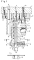
- the punching device shown in FIG. 1 has an upper press part 2 which can be moved up and down by an actuating device (not shown).
- a housing 4 is positioned on the press upper part 2 by means of centering pins 6, 8 and is clamped against the underside of the press upper part by two screws 10 or optionally by two clamping claws 12.
- the clamping claws 12 engage with projections in transverse grooves 16 of the housing and are fastened to the upper press part 2 by screws 14.
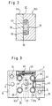
- the pressure plate 22 is fastened to the housing 4 by two screws 24 and the stamp 20 by two screws 30 (cf. also FIG. 3).
- a guide piece 32 is mounted in a longitudinally displaceable manner in a guide opening 34 arranged centrally in the housing 4.
- a channel 36 is formed in the center of the guide piece 32, in which the stamp 20 is slidably guided, so that the stamp 20 moves accordingly in the channel 36 when there is a relative displacement between the slide piece 32 and the housing 4.
- the guide piece 32 is biased in a direction away from the upper press part 2 by four helical compression springs 38 supported on the upper press part and distributed within the guide opening 34 around the punch 20.
- a latch 40 which is fixed to the housing 4 by a locking screw 42, projects with a projection into a slot 44 in the guide piece 32 in order to limit the outward movement of the guide piece 32 caused by the springs 38.
- the stamp 20 and the channel 36 have the same rectangular cross section.
- the guide piece 32 also has the same rectangular cross section as the guide opening 34. This ensures precise guidance and positioning of the plunger 20 relative to the guide piece 32 and of the guide piece 32 relative to the housing 34. At the same time, this cross-sectional selection ensures that the plunger 20 and the guide piece 32 are secured against rotation.
- the guide piece 32 is divided in a plane 50 which is connected to a side wall of the Channel 36 coincides. As shown in Fig. 3, the two parts 32a and 32b of the guide piece 32 are held together by screws 46 and centering sleeves 48. The division of the guide piece 32 facilitates the production of the channel 36.
- a nut feed device 54 (not shown in detail) with a feed line 58 which pushes nuts 60 into the channel 36 via a side feed opening 56.
- a stationary die 62 is arranged below the guide piece 32, on which a plate-shaped component 64 in the form of a sheet metal lies, into which the nut 60 located in the channel 36 is to be pressed by a downward movement of the press upper part 2.
- the guide piece 32 as soon as it rests with its underside on the sheet metal 64, relative to the housing 4 and the stamp 20, so that the stamp 20 adjoins the nut 60 located in the channel 36 from the starting point on the Feed opening 56 moves down through the channel to the work station on the plate 64.
- the channel 36 is aligned precisely with the stationary die 62. This is particularly important when the parts to be processed, e.g. rectangular nuts, pressed into the sheet 64 in the correct orientation or must be attached to it in some other way.
- the mutually displaceable parts such as the housing 4, the guide piece 32 and the stamp 20 expediently consist of materials which make lubrication unnecessary. So the housing 4 and the guide piece 32 as castings be made of bronze, while the stamp 20 may consist of a tool steel.
- a proximity switch 70 On the side of the channel 36 opposite the feed opening 56 there is a proximity switch 70 which acknowledges the correct position of the nut 60.
- the proximity switch 70 is located in a protective cap 72, which prevents damage to the proximity switch 70 by the nut.
- the proximity switch 70 and the protective cap 72 are attached to the guide piece 32 by a clamping plate 74.
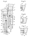
- a holding device 80 which precisely moves the nut 60 in its movement from the starting point (right side in FIG. 4) to the working point (left side in FIG. 4) holds its position.
- the holding device 80 consists of two holding claws 82, which are arranged in the longitudinal grooves 84 of the stamp 20 and are pivotably supported by bearing bolts 86 in elongated holes 88 of the stamp 20. This allows the holding claws 82 between a closed position in which they hold the nut in contact with the lower end of the stamp 20 (right side in FIG. 4, FIG. 8) and an open position in which they release the nut (left side in Fig. 4, Fig. 9) are pivoted, as will be explained in more detail.
- the holding claws 82 are assigned a positive guide 90, which holds the holding claws 82 in the closed position when the plunger 20 and thus the nut 60 move from the starting point to the working position.
- the positive guide 90 consists of guide surfaces 92, 94 provided on the holding claws 82 and the guide piece 32 which slide against one another during a relative movement between the guide piece 32 and the punch 20.
- the recesses 96 and 98 are provided with inclined surfaces 96a and 98a which, when the plunger 20 is retracted, pivot the holding claws 82 back into their closed position.
- the nut 60 is held in the closed position of the holding claws 82 on the punch 20 by an inclined surface connection 100.
- the inclined surface connection 100 is formed by inclined surfaces 104 provided on holding lugs 102 of the holding claws 82, which bear against an edge of the nut 60 and, when the longitudinal hole connection 86, 88 enables relative longitudinal displacement between the holding claws 82 and the punch 20, pivot the holding claws outward, as is the case is explained in more detail below.
- FIG. 1 shows the initial state in which a nut 60 has been inserted into the channel 36 by the nut feed device 54, namely between the underside of the stamp 20 and the inclined surfaces 104 of the retaining lugs 102 of the retaining claws 82, which are in their closed position (Right side of Fig. 4, Fig. 8). If the upper press part 2 with the parts attached to it is now moved downward, the underside of the guide piece 32 first lies against the plate 64 lying on the die 62. During the further downward movement of the press upper part 2, the guide piece 32 pushes against the prestressing force of the springs 38 into the guide opening 34, while at the same time the punch 20 slides downward in the channel 36.
- the holding claws 82 projecting beyond the stamp 20 and also above the nut 60 are placed on the sheet metal 64.
- the recesses 96 of the holding claws 82 reach the recesses 98 in the guide piece 32.
- the holding claws 82 and the stamp 20 can carry out a limited longitudinal displacement due to the elongated hole connection 86, 88, the stamp 20 with the nut 60 moves further downward.
- the nut 60 presses the holding claws 82 outwards into the open position via the inclined surfaces 104, which is made possible by the recesses 96, 98 (FIG. 9).
- the nut 60 is thus released from the holding claws 82 so that it can be pressed into the sheet 64 by the punch 82. Even during the press-in process, the nut 60 remains fixed in its position by contact with the holding lugs 102 of the holding claws 82.
- the inclined surfaces 96a, 98a of the recesses 96, 98 pivot the holding claws 82 back into their closed position.
- a cam projection 106 provided on the holding claws 82 cooperates with a cam surface in the form of the inclined surface 98a of the guide piece 32 during the retraction movement in order to reset the holding claws 82 again in the longitudinal direction. A new punching process can then begin again.
- the holding device described could be used for holding and transporting other elements 60 ′′ of any shape if a precise positional fixation is important when transporting the elements 60 ′′.
- the holding device described can be used in any device in which the elements have to be transported from a starting point in precise alignment to a work or transfer point.
- the holding device described can be used in an electrical welding device for welding a nut or another element to a plate-shaped component.
- the stamp 20 serves as an electrode and the stationary die 62 serves as a second electrode. There is then no punching through of the sheet metal part 64, since the die 62 is solid, i.e. is designed without a bore.
- the stamp 20 serving as the electrode only has to apply the contact pressure required for welding. It goes without saying that in this case power supply lines are provided for the electrodes, cooling channels, insulation, etc.
- 10 to 12 show another embodiment of a punching device for pressing nuts into a sheet with a somewhat differently designed holding device. 10 to 12, the same reference numerals have been used as in the previous figures, insofar as the components designated therewith match or correspond.
- the guide piece 32 of the punching device is not guided in the housing 4; rather, both components 4 and 32 have the same external dimensions and are arranged vertically one below the other.
- the guide 20 is guided relative to the housing 4 by the stamp 20, which is fixed in the housing 4 by means of a central screw 24 ′. Screws 40 'serve to limit the stroke in the event of a relative displacement between the guide piece 32 and the housing 4.
- the holding device which holds the nut 60 in position during its movement in the guide channel 36, has in principle the same structure as the holding device of the previous figures, but differs from the latter in the following features.
- springs 91 are provided according to FIG. 11, which are supported on the housing 4 and pretension the holding claws 82 'in the longitudinal direction downward (in the figures). The springs 91 thus ensure that the holding claws 82 'are reset in the elongated holes 88 when the stamp together with the holding claws 82' is moved back upwards after the nut 60 has been pressed in.
- the recess 98 provided at the lower end of the guide surface 94 of the guide piece 32 can be limited to a short length. Accordingly, the guide surface 92 of the respective holding claw 82 ', at the upper end of which the recess 96 is connected, can be limited to a short axial length at the lower end of the respective holding claw 82'.
- the holding claws 82' are provided on their inside, in the region of the contact surfaces 93 and 95, with a bevel 97, which extends from the contact surface 93 runs obliquely upwards at the level of the bolt 86.
- the operation of the holding device shown in Fig. 11 is in principle the same as that of the holding device according to the previous figures, except that the holding claws 82 'are reset by the springs 91 in their elongated holes relative to the punch 20 when the press-in process has ended the stamp 20 is moved back and the holding claws 82 'are pivoted inwards.
Landscapes
- Engineering & Computer Science (AREA)
- Mechanical Engineering (AREA)
- Combustion & Propulsion (AREA)
- Chemical & Material Sciences (AREA)
- Automatic Assembly (AREA)
- Details Of Spanners, Wrenches, And Screw Drivers And Accessories (AREA)
- Mounting, Exchange, And Manufacturing Of Dies (AREA)
- Clamps And Clips (AREA)
- Automobile Manufacture Line, Endless Track Vehicle, Trailer (AREA)
- Slide Fasteners (AREA)
- Connection Of Plates (AREA)
- Joints Allowing Movement (AREA)
- Press Drives And Press Lines (AREA)
- Slide Fasteners, Snap Fasteners, And Hook Fasteners (AREA)
Claims (22)
- Dispositif de maintien destiné à maintenir, à guider et à libérer automatiquement une pièce d'assemblage, comme par exemple un écrou ou un autre élément dans un appareil destiné à amener la pièce d'assemblage vers un composant en forme de plaque, ou dans un autre appareil pour transporter en position exacte l'élément, comprenant une pièce de guidage (32), qui présente un canal (36) auquel on peut amener l'élément (60) via une ouverture d'amenée latérale (56), comprenant une pièce coulissante (20), qui est déplaçable longitudinalement dans le canal (36) par un déplacement relatif entre la pièce de guidage et la pièce coulissante, afin de déplacer l'élément (70), dans un déplacement de déploiement, depuis un emplacement de départ voisin de l'ouverture d'admission (56) jusqu'à un emplacement de travail à une extrémité du canal (36), et comprenant au moins deux griffes de maintien (82), montées en basculement au moyen de goujons de montage (86) et qui maintiennent, dans une position de fermeture basculée vers l'intérieur, l'élément (60) en contact contre la pièce coulissante (20) et sont susceptibles d'être automatiquement basculées jusque dans une position d'ouverture qui libère l'élément (60), caractérisé en ce que les griffes de maintien (82) sont montées de manière basculante sur la pièce coulissante (20) de manière qu'elles se déplacent avec la pièce coulissante (20), et en ce qu'il est prévu pour les griffes de maintien (82) un guidage forcé (90), lequel maintient lors d'un déplacement de déploiement de la pièce coulissante (20) les griffes de maintien (82) dans leur position de fermeture et ne les libère pour basculer jusque dans la position d'ouverture que lorsque la pièce coulissante (20) atteint l'emplacement de travail à l'extrémité du canal (36).
- Dispositif de maintien selon la revendication 1, caractérisé en ce que le guidage forcé (90) comporte des surfaces de guidage (92, 94) prévues sur les griffes de maintien (82) et sur la pièce de guidage (32), lesquelles sont en contact de coulissement l'une contre l'autre lors d'un déplacement relatif entre la pièce de guidage (32) et la pièce coulissante (20), et empêchent ainsi un basculement vers l'extérieur des griffes de maintien (82).
- Dispositif de maintien selon la revendication 2, caractérisé en ce qu'une saillie postérieure (96, 98), qui sert d'élément de libération, se raccorde respectivement aux surfaces de guidage (92, 94), lesdites saillies permettant un basculement des griffes de maintien (82) vers l'extérieur lorsque la pièce coulissante (20) atteint l'emplacement de travail lors d'un déplacement de déploiement.
- Dispositif de maintien selon la revendication 3, caractérisé en ce que les saillies postérieures (96, 98) sont pourvues de surfaces obliques (96a, 96b) qui basculent les griffes de maintien (82) en retour jusque dans leur position de fermeture lors d'un déplacement de retrait de la pièce coulissante (20).
- Dispositif de maintien selon l'une des revendications précédentes, caractérisé en ce que les goujons de montage (86) des griffes de maintien (82) sont agencés dans des trous oblongs (88) de la pièce coulissante (20), afin de permettre un déplacement longitudinal limité des griffes de maintien (82) par rapport à la pièce coulissante (20), et en ce qu'il est prévu une jonction de surfaces obliques (100) entre les griffes de maintien (82) et la pièce coulissante (20), ladite jonction faisant basculer les griffes de maintien (82) jusque dans leur position ouverte lors d'un tel déplacement longitudinal.
- Dispositif de maintien selon la revendication 5, caractérisé en ce que les griffes de maintien (82) dépassent en direction longitudinale au-delà de la pièce coulissante (20), de sorte que lors d'un déplacement de déploiement de la pièce coulissante (20) elles sont arrêtées lorsqu'elles rencontrent une contre-surface stationnaire (62, 64) et exécutent ainsi par rapport à la pièce coulissante (20) le déplacement longitudinal nécessaire pour le basculement vers l'extérieur.
- Dispositif de maintien selon l'une ou l'autre des revendications 5 et 6, caractérisé en ce que la jonction de surfaces obliques (100) est constituée par des surfaces obliques (104) réalisées sur des doigts de maintien (102) des griffes de maintien (82) et qui sont en contact contre l'élément (60) dans la position de fermeture des griffes de maintien (82).
- Dispositif de maintien selon l'une des revendications 5 à 7, caractérisé en ce que les griffes de maintien (82) sont respectivement pourvues d'une saillie en forme de came (106), laquelle coopère lors d'un déplacement de retrait de la pièce coulissante (20) avec une surface de came de la pièce de guidage (32), afin de ramener les griffes de maintien (82) en direction longitudinale par rapport à la pièce coulissante (20).
- Dispositif de maintien selon l'une des revendications 5 à 7, caractérisé en ce que les griffes de maintien (82) sont précontraintes par des ressorts (91) en direction longitudinale de telle manière qu'elles sont reculées par rapport à la pièce coulissante (20) sous la force du ressort lors d'un déplacement de retrait de cette dernière.
- Dispositif de maintien selon l'une des revendications précédentes, caractérisé en ce que les griffes de maintien (82) sont agencées dans des gorges longitudinales (84) de la pièce coulissante (20).
- Dispositif de maintien selon l'une des revendications précédentes, caractérisé en ce que les goujons de montage (86) des griffes de maintien (82) sont assurés à l'encontre de leur perte par contact contre des surfaces de paroi du canal (36).
- Dispositif de maintien selon l'une des revendications précédentes, caractérisé en ce que la pièce coulissante est réalisée sous forme d'un poinçon (20) d'un dispositif de poinçonnage, lequel est fixé à un boîtier (4) d'une partie supérieure de presse (2), laquelle est mobile verticalement par rapport à une matrice (62) qui reçoit le composant en forme de plaque (64).
- Dispositif de maintien selon la revendication 12, caractérisé en ce que le canal (36) qui reçoit le poinçon (20) est agencé au milieu dans la pièce de guidage (32), et en ce que la pièce de guidage (32) est montée en déplacement dans une ouverture de guidage (34) agencée au milieu du boîtier (4).
- Dispositif de maintien selon la revendication 13, caractérisé en ce que la pièce de guidage (32) est précontrainte en éloignement de la partie supérieure de presse (2) au moyen de ressorts (38) agencés à l'intérieur de l'ouverture de guidage (34) autour du poinçon (20).
- Dispositif de maintien selon l'une ou l'autre des revendications 13 et 14, caractérisé en ce que le canal (36) et/ou l'ouverture de guidage (34) présentent une section rectangulaire.
- Dispositif de maintien selon l'une des revendications précédentes, caractérisé en ce que la pièce de guidage (32) est divisée pour faciliter la réalisation du canal (36), et en ce que les deux parties (32a, 32b) sont maintenues ensemble par des organes de fixation détachables (46, 48).
- Dispositif de maintien selon l'une des revendications 12 à 16, caractérisé en ce que le poinçon (20) est fixé sur le boîtier (4) au moyen d'une plaque de pression (22) agencée sur le fond de l'ouverture de guidage (34) et d'une tige de centrage (26) qui traverse la plaque de pression (22).
- Dispositif de maintien selon l'une des revendications 12 à 17, caractérisé en ce que le boîtier (4) est monté sur la partie supérieure de presse (2) au choix au moyen de vis de fixation (10) ou de griffes de serrage (12) en utilisant des tiges de centrage (6, 8).
- Dispositif de maintien selon l'une des revendications précédentes, caractérisé en ce que, du côté du canal (36) opposé à l'ouverture d'amenée (56) est prévu un commutateur de proximité (70) pour constater la présence d'un élément (60).
- Dispositif de maintien selon l'une des revendications précédentes, caractérisé en ce que la pièce coulissante (20) et la pièce de guidage (32) sont réalisées en matériaux qui rendent superflus une lubrification, et en ce que la pièce de guidage (32) est réalisée en particulier en bronze et la pièce de coulissement (20) est réalisée en particulier en acier à outils.
- Dispositif de maintien selon l'une des revendications 1 à 12, caractérisé en ce que le dispositif de maintien fait partie d'un appareil de soudage électrique pour souder un écrou ou une autre pièce d'assemblage sur le composant en forme de plaque, et dans lequel la pièce coulissante (20) sert de première électrode et une contre-surface stationnaire (62) qui soutient l'élément en forme de plaque (64) sert de seconde électrode, qui sont alimentées en puissance électrique par des alimentations de courant.
- Procédé pour mettre en place une pièce d'assemblage ou une pièce d'assemblage accessoire (60) dans un composant en forme de plaque (75) au moyen d'un appareil pour enfoncer ou pour fixer des pièces d'assemblage ou des pièces d'assemblage accessoires, comme par exemple des écrous, des goujons, des rivets, dans des composants en forme de plaque (75), caractérisé en ce que la pièce d'assemblage ou la pièce d'assemblage accessoire (60) est maintenue, après transmission à l'appareil, sur tout le trajet jusqu'au composant en forme de plaque (75) sans autre transmission entre les éléments (20, 82) de l'appareil.
Applications Claiming Priority (3)
| Application Number | Priority Date | Filing Date | Title |
|---|---|---|---|
| DE4211276 | 1992-04-03 | ||
| DE4211276A DE4211276C2 (de) | 1992-04-03 | 1992-04-03 | Haltevorrichtung zum Halten, Führen und Freigeben eines Fügeteils, wie z.B. einer Mutter |
| PCT/EP1993/000836 WO1993019890A1 (fr) | 1992-04-03 | 1993-04-02 | Dispositif de retenue de pieces d'assemblage |
Publications (2)
| Publication Number | Publication Date |
|---|---|
| EP0633824A1 EP0633824A1 (fr) | 1995-01-18 |
| EP0633824B1 true EP0633824B1 (fr) | 1997-05-21 |
Family
ID=6456027
Family Applications (1)
| Application Number | Title | Priority Date | Filing Date |
|---|---|---|---|
| EP93908905A Expired - Lifetime EP0633824B1 (fr) | 1992-04-03 | 1993-04-02 | Dispositif de retenue de pieces d'assemblage |
Country Status (10)
| Country | Link |
|---|---|
| US (3) | US5636426A (fr) |
| EP (1) | EP0633824B1 (fr) |
| JP (1) | JP3101684B2 (fr) |
| KR (1) | KR100271755B1 (fr) |
| AT (1) | ATE153268T1 (fr) |
| AU (1) | AU3951793A (fr) |
| CA (1) | CA2133438C (fr) |
| CZ (1) | CZ285580B6 (fr) |
| DE (2) | DE4211276C2 (fr) |
| WO (1) | WO1993019890A1 (fr) |
Families Citing this family (42)
| Publication number | Priority date | Publication date | Assignee | Title |
|---|---|---|---|---|
| DE4211276C2 (de) | 1992-04-03 | 1997-08-28 | Profil Verbindungstechnik Gmbh | Haltevorrichtung zum Halten, Führen und Freigeben eines Fügeteils, wie z.B. einer Mutter |
| DE4310953A1 (de) * | 1993-04-02 | 1994-10-13 | Wolfgang Dipl Ing Luckhardt | Einpresseinrichtung zum Einpressen von Fügeteilen |
| US6009309A (en) * | 1993-05-04 | 1999-12-28 | Motorola, Inc. | Method of operation a combination radiotelephone and paging device and method of operation |
| JP2537135B2 (ja) * | 1994-02-10 | 1996-09-25 | 有限会社新城製作所 | ピアスナット打込み装置 |
| DE4447620C2 (de) * | 1994-06-10 | 2003-01-23 | Profil Verbindungstechnik Gmbh | Haltefinger und Setzkopf mit mehreren solchen Haltefingern |
| DE4429737A1 (de) * | 1994-06-10 | 1995-12-14 | Profil Verbindungstechnik Gmbh | Setzkopf und Verfahren zum Betrieb desselben |
| JPH11507597A (ja) * | 1995-06-07 | 1999-07-06 | マルチファスナー・コーポレーション | 組立部品用保持装置 |
| EP0755749B2 (fr) * | 1995-06-07 | 2006-06-07 | PROFIL-Verbindungstechnik GmbH & Co. KG | Dispositif de guidage et/ou de fixation pour éléments, particulièrement pour éléments de fixation |
| DE19815407A1 (de) | 1998-04-06 | 1999-10-07 | Profil Verbindungstechnik Gmbh | Verbindungseinrichtung zum Verbinden zweier Bauteile, Kombination der Verbindungseinrichtung mit den beiden Bauteilen und Verfahren zur Herstellung einer Verbindung zwischen zwei Bauteilen |
| DE19848617A1 (de) * | 1998-10-21 | 2000-04-27 | Profil Verbindungstechnik Gmbh | Verfahren zur Herstellung einer elektrischen Verbindung zu einem Blechteil und Zusammenbauteil |
| US6148507A (en) * | 1999-03-12 | 2000-11-21 | Swanson; Jeffery S | Machine for pressing a fastener through sheet metal studs |
| DE19922864A1 (de) * | 1999-05-19 | 2000-12-07 | Rudolf Mueller | Verfahren und Vorrichtung zum Befestigen eines Hilfsfügeteils an einem blechartigen Werkstück und Werkstück mit Hilfsfügeteil |
| EP1249305B1 (fr) * | 1999-07-09 | 2007-01-17 | Profil Verbindungstechnik GmbH & Co. KG | Ensemble poinçon |
| US6631827B2 (en) * | 2002-03-01 | 2003-10-14 | Fabristeel Products, Inc. | Fastener feed and installation head |
| ATE458581T1 (de) * | 2003-03-19 | 2010-03-15 | Fabristeel Prod Inc | Selbstdiagnostizierende vorrichtung zur befestigung von selbststanzenden muttern |
| US6912776B2 (en) * | 2003-06-24 | 2005-07-05 | Fabristeel Products, Inc. | Pierce nut installation apparatus |
| DE10347477A1 (de) * | 2003-09-10 | 2005-04-21 | Minebea Co Ltd | Vorrichtung zum Einpressen einer Welle eines Rotors in ein Statorgehäuse |
| US7415758B2 (en) | 2003-09-10 | 2008-08-26 | Minebea Co., Ltd. | Device to press the shaft of a rotor into a stator housing |
| JP4618643B2 (ja) | 2005-03-11 | 2011-01-26 | ヤマハファインテック株式会社 | ワークの把持機構およびそれを用いた把持システム |
| DE102006016255A1 (de) * | 2006-03-31 | 2007-10-04 | Arnold & Shinjo Gmbh & Co. Kg | Einpressen von Bolzen |
| JP4628376B2 (ja) * | 2007-01-22 | 2011-02-09 | 富士重工業株式会社 | 圧入装置 |
| DE102008033933B4 (de) * | 2007-07-19 | 2013-01-31 | Richard Bergner Verbindungstechnik Gmbh & Co. Kg | Verarbeitungswerkzeug sowie Verfahren zum Überführen eines Bauteils aus einer Bereitstellungsposition in eine Verarbeitungsposition |
| TW200920562A (en) * | 2007-11-02 | 2009-05-16 | Jann Yei Industry Co Ltd | Staple gun safety device |
| US8585000B2 (en) | 2008-05-22 | 2013-11-19 | Mainstream Energy Corporation | Universal end clamp |
| JP2010036214A (ja) * | 2008-08-05 | 2010-02-18 | Nippon Pop Rivets & Fasteners Ltd | セルフピアスリベット締結機 |
| JP5513964B2 (ja) * | 2010-04-19 | 2014-06-04 | 株式会社大武ルート工業 | 自動ネジ締め装置 |
| US8881364B2 (en) | 2010-12-03 | 2014-11-11 | Btm Corporation | Pierce nut insertion tool |
| DE102011077433A1 (de) * | 2011-06-10 | 2012-12-13 | Hilti Aktiengesellschaft | Eintreibelement, Transporteinrichtung und Eintreibvorrichtung |
| US8769789B2 (en) | 2011-06-17 | 2014-07-08 | Btm Corporation | Die for rivet machine |
| US8869365B2 (en) | 2011-06-24 | 2014-10-28 | Btm Corporation | Rivet guide head |
| US9223095B2 (en) * | 2013-03-21 | 2015-12-29 | Molex, Llc | Connector with interface protection |
| KR101505910B1 (ko) * | 2013-08-05 | 2015-03-25 | 주식회사 성우하이텍 | 셀프 피어싱 리벳 장치 |
| DE102014002571A1 (de) | 2014-02-26 | 2015-08-27 | Tox Pressotechnik Gmbh & Co. Kg | Vorrichtung und Werkzeug zum Anbringen eines Füge- oder Funktionselements an einem Bauteilabschnitt |
| MY193272A (en) | 2016-06-29 | 2022-09-29 | Valinge Innovation Ab | Method and device for inserting a tongue |
| JP7053506B2 (ja) * | 2016-06-29 | 2022-04-12 | ベーリンゲ、イノベイション、アクチボラグ | タングを挿入するための方法及び装置 |
| WO2018004440A1 (fr) | 2016-06-29 | 2018-01-04 | Välinge Innovation AB | Procédé et dispositif de gestion et de séparation d'une languette à partir d'une ébauche de langue |
| WO2018004435A1 (fr) | 2016-06-30 | 2018-01-04 | Välinge Innovation AB | Dispositif d'insertion d'une languette |
| US10953566B2 (en) | 2016-12-22 | 2021-03-23 | Valinge Innovation Ab | Device for inserting a tongue |
| EP3403787B1 (fr) * | 2017-05-19 | 2019-07-31 | Joh. Friedrich Behrens AG | Agrafeuse destinée à enfoncer des moyens de fixation dans des pièces |
| EP3718437A1 (fr) | 2019-04-05 | 2020-10-07 | Välinge Innovation AB | Méthode d'assemblage d'un meuble |
| DE102019110011A1 (de) * | 2019-04-16 | 2020-10-22 | Böllhoff Verbindungstechnik GmbH | Setzkopf, Blechpresse oder Setzgerät mit diesem Setzkopf sowie ein Fügeverfahren eines Fügeelements mit dem Setzkopf |
| EP4596137A1 (fr) * | 2024-01-30 | 2025-08-06 | Newfrey LLC | Procédé d'assemblage pour assembler des pièces et dispositif d'assemblage |
Family Cites Families (49)
| Publication number | Priority date | Publication date | Assignee | Title |
|---|---|---|---|---|
| US28608A (en) * | 1860-06-05 | Elastic lining for boom-jaws | ||
| GB930165A (fr) * | 1900-01-01 | |||
| US1240207A (en) | 1917-01-26 | 1917-09-18 | Henry C Hinchcliff | Punching and setting machine. |
| US1503861A (en) * | 1922-06-07 | 1924-08-05 | Stimpson Edwin B Co | Rivet guide |
| US1506788A (en) * | 1922-07-19 | 1924-09-02 | Stimpson Edwin B Co | Guide for riveting machines |
| DE539493C (de) * | 1930-06-07 | 1931-11-26 | Patra Patent Treuhand | Kontaktkoerper fuer elektrische Unterbrecher u. dgl. |
| US2595551A (en) | 1947-05-23 | 1952-05-06 | Aviat Developments Ltd | Feeding device for rivets or similar articles |
| US2658538A (en) | 1951-10-29 | 1953-11-10 | Donald M Kitterman | Screw-retaining clamp for power-driven screw drivers |
| GB825223A (en) * | 1956-07-05 | 1959-12-09 | Nat Res Dev | Improvements in or relating to article feeding mechanisms |
| US3152628A (en) | 1958-07-17 | 1964-10-13 | Multifastener Corp | Clinch nut |
| DE1254940B (de) | 1960-01-16 | 1967-11-23 | Multifastener Corp | Vorrichtung zum Einpressen von vorgefertigten, ihr Aufnahmeloch selbst stanzenden Muttern |
| US3061837A (en) * | 1961-08-07 | 1962-11-06 | Samuel J Kent | Nail-driving and clinching machine |
| US3368431A (en) * | 1966-05-12 | 1968-02-13 | Tru Tork Inc | Nut-running apparatus |
| US3526943A (en) | 1968-05-23 | 1970-09-08 | United Carr Inc | Tool head assembly |
| SE326141B (fr) * | 1968-07-08 | 1970-07-13 | Atlas Copco Ab | |
| US3780417A (en) | 1968-09-20 | 1973-12-25 | Amp Inc | Installation tooling for plastic locking nut in strip form |
| CH539493A (de) | 1972-02-25 | 1973-07-31 | Haas Arthur | Schraubenzieher mit einer Schraubenkopffassung und einer dieser zugeordneten Halteeinrichtung für den Kopf einer in die Schraubenkopffassung eingesetzten Schraube |
| DE2263648A1 (de) * | 1972-12-27 | 1974-07-04 | Feldpausch & Co | Schraubkopf an einer schraubmaschine |
| US4002265A (en) | 1974-10-25 | 1977-01-11 | Babette Dixon, Trustee of a trust identified as Paul H. Dixon Trust | Apparatus for pneumatically delivering parts |
| US3971116A (en) * | 1975-05-05 | 1976-07-27 | Multifastener Corporation | Fastener installation head |
| US4242793A (en) | 1979-05-25 | 1981-01-06 | Multifastener Corporation | Nut guide for installation head |
| US4313261A (en) | 1980-01-11 | 1982-02-02 | Multifastener Corporation | Nut installation apparatus |
| DE3003908C2 (de) * | 1980-02-02 | 1984-10-18 | Profil-Verbindungstechnik Gmbh & Co Kg, 6382 Friedrichsdorf | Stehbolzen mit Stanz- und Nietverhalten |
| US4831698A (en) | 1983-03-28 | 1989-05-23 | Multifastener Corporation | Method of attaching a female element to a panel |
| US5237733A (en) | 1980-02-02 | 1993-08-24 | Multifastener Corporation | Female die assembly for attaching a self-attaching fastening element and method of attachment |
| US4555838A (en) | 1983-03-28 | 1985-12-03 | Multifastener Corp. | Method of installing self-attaching fasteners |
| US4700470A (en) | 1980-02-02 | 1987-10-20 | Multifastener Corporation | Fastener installation apparatus |
| JPS56147085U (fr) * | 1980-04-04 | 1981-11-05 | ||
| US4459735A (en) * | 1980-09-08 | 1984-07-17 | Btm Corporation | Joining sheet metal |
| US4384667A (en) | 1981-04-29 | 1983-05-24 | Multifastener Corporation | Fastener installation tool and bolster assembly |
| SE431417B (sv) | 1982-04-28 | 1984-02-06 | Jonny Karl Gyris Andersson | Anordning for indrivning av festelement |
| US4454650A (en) * | 1982-08-23 | 1984-06-19 | U.S. Industries, Inc. | Upper jaw and tool assembly for fastener attaching machine |
| DE8227676U1 (de) * | 1982-10-02 | 1985-03-28 | Fehlings, Herbert, 6228 Eltville | Auslauf eines mundstueckes von drehschraubern, schlagschraubern, niethaemmern udgl. |
| US4607418A (en) * | 1983-11-18 | 1986-08-26 | Hafner Otto P | Means for interlocking overlapping sheet material |
| GB8406129D0 (en) | 1984-03-08 | 1984-04-11 | Dyna Pert Precima Ltd | Orienting electrical components |
| JPS60189298A (ja) | 1984-03-08 | 1985-09-26 | 松下電器産業株式会社 | リ−ド線挾持装置 |
| JPH0232650Y2 (fr) * | 1985-07-10 | 1990-09-04 | ||
| US4744238A (en) | 1986-07-02 | 1988-05-17 | Senco Products, Inc. | Pneumatic rivet setting tool |
| JPH0527459Y2 (fr) | 1988-05-09 | 1993-07-13 | ||
| DE3820898A1 (de) * | 1988-05-09 | 1989-11-23 | Lorenz Stoeger | Schraubvorrichtung |
| DE3937903C2 (de) * | 1989-10-28 | 1995-11-09 | Schmidt Dieter Maschbau | Verfahren zum Verbinden wenigstens eines ersten Werkstückteils an einem zweiten Werkstückteil in einem als Stanz- und/oder Umformwerkzeug ausgebildeten Folgewerkzeug, sowie ein derartiges Folgewerkzeug |
| JPH05208328A (ja) | 1992-01-28 | 1993-08-20 | Aoyama Seisakusho:Kk | ナット類の供給装置 |
| DE4211276C2 (de) * | 1992-04-03 | 1997-08-28 | Profil Verbindungstechnik Gmbh | Haltevorrichtung zum Halten, Führen und Freigeben eines Fügeteils, wie z.B. einer Mutter |
| EP0567240B2 (fr) | 1992-04-21 | 2003-07-16 | Ariel Industries Plc | Tube d'alimentation pour éléments de fixation |
| DE4215008C1 (de) | 1992-05-06 | 1993-11-11 | Sfs Stadler Holding Ag Heerbru | Vorrichtung zum Setzen eines selbstbohrenden Klemmbefestigers |
| US5469610A (en) | 1993-08-16 | 1995-11-28 | Courian; Curtis C. | Fastening tool and fastener |
| US5435056A (en) | 1993-10-15 | 1995-07-25 | Micro-Precision Operations, Inc. | Piston ring apparatus |
| US5479687A (en) * | 1994-01-31 | 1996-01-02 | Btm Corporation | Apparatus for joining sheets of material |
| DE4423165C2 (de) | 1994-07-04 | 1996-06-20 | Michael Feldpausch | Vorrichtung zum Bereitstellen von Befestigungselementen |
-
1992
- 1992-04-03 DE DE4211276A patent/DE4211276C2/de not_active Expired - Fee Related
-
1993
- 1993-04-02 AU AU39517/93A patent/AU3951793A/en not_active Abandoned
- 1993-04-02 KR KR1019940703470A patent/KR100271755B1/ko not_active Expired - Fee Related
- 1993-04-02 EP EP93908905A patent/EP0633824B1/fr not_active Expired - Lifetime
- 1993-04-02 DE DE59306535T patent/DE59306535D1/de not_active Expired - Lifetime
- 1993-04-02 US US08/307,849 patent/US5636426A/en not_active Expired - Fee Related
- 1993-04-02 AT AT93908905T patent/ATE153268T1/de not_active IP Right Cessation
- 1993-04-02 JP JP05517117A patent/JP3101684B2/ja not_active Expired - Fee Related
- 1993-04-02 CA CA002133438A patent/CA2133438C/fr not_active Expired - Fee Related
- 1993-04-02 WO PCT/EP1993/000836 patent/WO1993019890A1/fr not_active Ceased
- 1993-04-02 CZ CZ942412A patent/CZ285580B6/cs not_active IP Right Cessation
-
1995
- 1995-06-07 US US08/482,760 patent/US5953813A/en not_active Expired - Fee Related
-
1999
- 1999-04-07 US US09/287,706 patent/US6263561B1/en not_active Expired - Fee Related
Also Published As
| Publication number | Publication date |
|---|---|
| CA2133438A1 (fr) | 1993-10-14 |
| DE4211276C2 (de) | 1997-08-28 |
| CA2133438C (fr) | 1999-07-27 |
| US5953813A (en) | 1999-09-21 |
| CZ241294A3 (en) | 1995-02-15 |
| WO1993019890A1 (fr) | 1993-10-14 |
| ATE153268T1 (de) | 1997-06-15 |
| DE59306535D1 (de) | 1997-06-26 |
| US5636426A (en) | 1997-06-10 |
| KR950700807A (ko) | 1995-02-20 |
| EP0633824A1 (fr) | 1995-01-18 |
| AU3951793A (en) | 1993-11-08 |
| KR100271755B1 (ko) | 2000-11-15 |
| DE4211276A1 (de) | 1993-10-14 |
| JPH09500330A (ja) | 1997-01-14 |
| CZ285580B6 (cs) | 1999-09-15 |
| US6263561B1 (en) | 2001-07-24 |
| JP3101684B2 (ja) | 2000-10-23 |
Similar Documents
| Publication | Publication Date | Title |
|---|---|---|
| EP0633824B1 (fr) | Dispositif de retenue de pieces d'assemblage | |
| DE102017203943B4 (de) | Setzeinheit und Verfahren zum Setzen eines Verbindungselements an einem Werkstück | |
| EP0755749B2 (fr) | Dispositif de guidage et/ou de fixation pour éléments, particulièrement pour éléments de fixation | |
| DE2747164A1 (de) | Vorrichtung zur handhabung elektrischer bauteile | |
| EP3284548A1 (fr) | Procédé et appareil de pose d'un élément de fixation | |
| EP3825029A1 (fr) | Drageoir | |
| DE102022119104A1 (de) | Verbinderbestückungsanordnung für Montageanlage für elektrische Verbinder | |
| DE3120093A1 (de) | Nietmaschine, insbesondere zum aufnieten der bremsbelaege auf den belagtraeger von bremsbacken | |
| DE3423543A1 (de) | Presse und verfahren zur herstellung derselben | |
| WO2019029898A1 (fr) | Procédé et dispositif de fourniture de vis | |
| EP0426798A1 (fr) | Dispositif de manipulation d'objets et son application. | |
| DE2706817A1 (de) | Blechstreifen-aushebeeinrichtung fuer folgeschnitt-stanz- und praegewerkzeuge | |
| DE69009443T2 (de) | Stanz- und Formmaschine mit auswechselbaren Hilfsbauteilen. | |
| DE10101304A1 (de) | Muttereinstanzeinrichtung | |
| DE2259921C2 (de) | Maschine zum Abtrennen der Anschlußklemmen von einem Trägerstreifen | |
| DE1566982C3 (de) | Vorrichtung zum Befestigen von elektrischen Verbindern an einer Platte | |
| DE2334485B2 (de) | Stanzeinheit | |
| DE2950460A1 (de) | Vorrichtung zum einsetzen von anschlussstiften | |
| DE1937818A1 (de) | Verfahren und Vorrichtung zum Ausstanzen sechseckiger Rohlinge | |
| DE9205608U1 (de) | Haltevorrichtung für Fügeteile | |
| DE10035427A1 (de) | Vorrichtung zum Eindrücken von Schrauben | |
| EP4400730B1 (fr) | Pince et procédé de serrage d'une pièce à serrer à l'aide d'une pince | |
| DE68915720T2 (de) | Schneid-, Einfüg- und Krimpwerkzeug für isolationsverdrängende elektrische Verbinder. | |
| DE2642651C3 (de) | Präzisions-Stanzwerkzeug | |
| DE3136413C2 (fr) |
Legal Events
| Date | Code | Title | Description |
|---|---|---|---|
| PUAI | Public reference made under article 153(3) epc to a published international application that has entered the european phase |
Free format text: ORIGINAL CODE: 0009012 |
|
| 17P | Request for examination filed |
Effective date: 19941004 |
|
| AK | Designated contracting states |
Kind code of ref document: A1 Designated state(s): AT DE ES FR GB IT SE |
|
| 17Q | First examination report despatched |
Effective date: 19950328 |
|
| GRAG | Despatch of communication of intention to grant |
Free format text: ORIGINAL CODE: EPIDOS AGRA |
|
| RAP1 | Party data changed (applicant data changed or rights of an application transferred) |
Owner name: PROFIL-VERBINDUNGSTECHNIK GMBH & CO. KG |
|
| GRAH | Despatch of communication of intention to grant a patent |
Free format text: ORIGINAL CODE: EPIDOS IGRA |
|
| GRAH | Despatch of communication of intention to grant a patent |
Free format text: ORIGINAL CODE: EPIDOS IGRA |
|
| GRAA | (expected) grant |
Free format text: ORIGINAL CODE: 0009210 |
|
| ITF | It: translation for a ep patent filed | ||
| AK | Designated contracting states |
Kind code of ref document: B1 Designated state(s): AT DE ES FR GB IT SE |
|
| PG25 | Lapsed in a contracting state [announced via postgrant information from national office to epo] |
Ref country code: ES Free format text: THE PATENT HAS BEEN ANNULLED BY A DECISION OF A NATIONAL AUTHORITY Effective date: 19970521 |
|
| REF | Corresponds to: |
Ref document number: 153268 Country of ref document: AT Date of ref document: 19970615 Kind code of ref document: T |
|
| REF | Corresponds to: |
Ref document number: 59306535 Country of ref document: DE Date of ref document: 19970626 |
|
| ET | Fr: translation filed | ||
| PG25 | Lapsed in a contracting state [announced via postgrant information from national office to epo] |
Ref country code: SE Effective date: 19970821 |
|
| GBT | Gb: translation of ep patent filed (gb section 77(6)(a)/1977) |
Effective date: 19970805 |
|
| PLBE | No opposition filed within time limit |
Free format text: ORIGINAL CODE: 0009261 |
|
| STAA | Information on the status of an ep patent application or granted ep patent |
Free format text: STATUS: NO OPPOSITION FILED WITHIN TIME LIMIT |
|
| 26N | No opposition filed | ||
| PGFP | Annual fee paid to national office [announced via postgrant information from national office to epo] |
Ref country code: GB Payment date: 19990324 Year of fee payment: 7 |
|
| PGFP | Annual fee paid to national office [announced via postgrant information from national office to epo] |
Ref country code: FR Payment date: 19990420 Year of fee payment: 7 |
|
| PGFP | Annual fee paid to national office [announced via postgrant information from national office to epo] |
Ref country code: AT Payment date: 19990422 Year of fee payment: 7 |
|
| PG25 | Lapsed in a contracting state [announced via postgrant information from national office to epo] |
Ref country code: GB Free format text: LAPSE BECAUSE OF NON-PAYMENT OF DUE FEES Effective date: 20000402 Ref country code: AT Free format text: LAPSE BECAUSE OF NON-PAYMENT OF DUE FEES Effective date: 20000402 |
|
| GBPC | Gb: european patent ceased through non-payment of renewal fee |
Effective date: 20000402 |
|
| PG25 | Lapsed in a contracting state [announced via postgrant information from national office to epo] |
Ref country code: FR Free format text: LAPSE BECAUSE OF NON-PAYMENT OF DUE FEES Effective date: 20001229 |
|
| REG | Reference to a national code |
Ref country code: FR Ref legal event code: ST |
|
| PG25 | Lapsed in a contracting state [announced via postgrant information from national office to epo] |
Ref country code: IT Free format text: LAPSE BECAUSE OF NON-PAYMENT OF DUE FEES Effective date: 20050402 |
|
| PGFP | Annual fee paid to national office [announced via postgrant information from national office to epo] |
Ref country code: DE Payment date: 20120629 Year of fee payment: 20 |
|
| REG | Reference to a national code |
Ref country code: DE Ref legal event code: R071 Ref document number: 59306535 Country of ref document: DE |
|
| REG | Reference to a national code |
Ref country code: DE Ref legal event code: R071 Ref document number: 59306535 Country of ref document: DE |
|
| PG25 | Lapsed in a contracting state [announced via postgrant information from national office to epo] |
Ref country code: DE Free format text: LAPSE BECAUSE OF EXPIRATION OF PROTECTION Effective date: 20130403 |