EP0634005B1 - Detecteur aux infrarouges - Google Patents
Detecteur aux infrarouges Download PDFInfo
- Publication number
- EP0634005B1 EP0634005B1 EP94906220A EP94906220A EP0634005B1 EP 0634005 B1 EP0634005 B1 EP 0634005B1 EP 94906220 A EP94906220 A EP 94906220A EP 94906220 A EP94906220 A EP 94906220A EP 0634005 B1 EP0634005 B1 EP 0634005B1
- Authority
- EP
- European Patent Office
- Prior art keywords
- cold
- shield
- cold shield
- internal
- arrangement according
- Prior art date
- Legal status (The legal status is an assumption and is not a legal conclusion. Google has not performed a legal analysis and makes no representation as to the accuracy of the status listed.)
- Expired - Lifetime
Links
- 230000005855 radiation Effects 0.000 title claims abstract description 15
- 230000003287 optical effect Effects 0.000 claims abstract description 25
- 239000003518 caustics Substances 0.000 claims description 7
- 238000012216 screening Methods 0.000 claims 1
- 238000011144 upstream manufacturing Methods 0.000 abstract description 10
- 239000012212 insulator Substances 0.000 abstract 5
- NMFHJNAPXOMSRX-PUPDPRJKSA-N [(1r)-3-(3,4-dimethoxyphenyl)-1-[3-(2-morpholin-4-ylethoxy)phenyl]propyl] (2s)-1-[(2s)-2-(3,4,5-trimethoxyphenyl)butanoyl]piperidine-2-carboxylate Chemical compound C([C@@H](OC(=O)[C@@H]1CCCCN1C(=O)[C@@H](CC)C=1C=C(OC)C(OC)=C(OC)C=1)C=1C=C(OCCN2CCOCC2)C=CC=1)CC1=CC=C(OC)C(OC)=C1 NMFHJNAPXOMSRX-PUPDPRJKSA-N 0.000 description 48
- 238000001816 cooling Methods 0.000 description 10
- 210000001747 pupil Anatomy 0.000 description 5
- 238000004364 calculation method Methods 0.000 description 4
- 239000007787 solid Substances 0.000 description 3
- 230000004323 axial length Effects 0.000 description 1
- 238000006243 chemical reaction Methods 0.000 description 1
- 238000010276 construction Methods 0.000 description 1
- 230000001419 dependent effect Effects 0.000 description 1
- 238000005516 engineering process Methods 0.000 description 1
- 238000003384 imaging method Methods 0.000 description 1
- 230000002452 interceptive effect Effects 0.000 description 1
- 238000013507 mapping Methods 0.000 description 1
- 238000002310 reflectometry Methods 0.000 description 1
- 238000009420 retrofitting Methods 0.000 description 1
Images
Classifications
-
- G—PHYSICS
- G02—OPTICS
- G02B—OPTICAL ELEMENTS, SYSTEMS OR APPARATUS
- G02B27/00—Optical systems or apparatus not provided for by any of the groups G02B1/00 - G02B26/00, G02B30/00
- G02B27/0018—Optical systems or apparatus not provided for by any of the groups G02B1/00 - G02B26/00, G02B30/00 with means for preventing ghost images
-
- G—PHYSICS
- G01—MEASURING; TESTING
- G01J—MEASUREMENT OF INTENSITY, VELOCITY, SPECTRAL CONTENT, POLARISATION, PHASE OR PULSE CHARACTERISTICS OF INFRARED, VISIBLE OR ULTRAVIOLET LIGHT; COLORIMETRY; RADIATION PYROMETRY
- G01J5/00—Radiation pyrometry, e.g. infrared or optical thermometry
- G01J5/02—Constructional details
- G01J5/06—Arrangements for eliminating effects of disturbing radiation; Arrangements for compensating changes in sensitivity
- G01J5/061—Arrangements for eliminating effects of disturbing radiation; Arrangements for compensating changes in sensitivity by controlling the temperature of the apparatus or parts thereof, e.g. using cooling means or thermostats
-
- G—PHYSICS
- G02—OPTICS
- G02B—OPTICAL ELEMENTS, SYSTEMS OR APPARATUS
- G02B5/00—Optical elements other than lenses
- G02B5/005—Diaphragms
- G02B5/006—Diaphragms cooled
-
- H—ELECTRICITY
- H10—SEMICONDUCTOR DEVICES; ELECTRIC SOLID-STATE DEVICES NOT OTHERWISE PROVIDED FOR
- H10F—INORGANIC SEMICONDUCTOR DEVICES SENSITIVE TO INFRARED RADIATION, LIGHT, ELECTROMAGNETIC RADIATION OF SHORTER WAVELENGTH OR CORPUSCULAR RADIATION
- H10F77/00—Constructional details of devices covered by this subclass
- H10F77/60—Arrangements for cooling, heating, ventilating or compensating for temperature fluctuations
Definitions
- the invention relates to an infrared radiation detector device according to the preamble of claim 1.
- an infrared radiation detector device which has a cooled dewar in which there is an infrared receiver, preferably a flat detector element (focal plane array), and that for infrared -Optics (IR optics) is closed by an IR window that is transparent to infrared rays.
- the Dewar consists of a housing connected to a vacuum, which is closed off from the outside by the IR window. Inside the housing, opposite the IR window, there is an inner cold shield connected to a cooling device, which comprises an inner cold screen and whose cooled bottom wall serves as a carrier for the flat detector element.
- the Dewar is preceded in the direction of light by an outer cold shield thermally separated from the cooling device, which is designed and arranged relative to the inner cold shield in such a way that the opening of the inner cold shield through the outer Cold shield is mapped in itself.
- the outer cold shield is designed, for example, as an internally mirrored concave mirror with an opening forming an outer cold diaphragm, the center of curvature being in the center of the opening of the inner cold diaphragm.
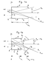
- the known cold shield is designated without the dewar and the outer cold shield in a schematic sketch in FIG. 1 a of the attached drawing.
- the cooling device is also not shown.
- the inner cold screen 6 At a distance z o from the image plane on the surface of the detector element 3 is the inner cold screen 6 with a central opening 7.
- the cold screen 6 connects to the cooled side walls 4 and 5, and can also be cooled.
- the opening 7 of the cold aperture 6 has a selected edge height h o from the optical axis x.
- the cold aperture ratio k o is determined by z o / 2h o , where z o is the distance of the opening 7 of the cold aperture 6 from the image plane and h o is the edge height h o of the cold aperture.
- the image height y o on the surface of the detector element 3 is a maximum of ⁇ d.
- the inner cold screen 6 forms the aperature screen and provides the exit pupil of the IR optics, not shown.
- the outer cold shield known from the prior art mentioned at the outset is also not shown in FIG. 1a, since it has no influence whatsoever on the spatial design of the dewar or the inner cold shield.
- a relatively large distance z o between the image plane on the surface of the flat detector element 3 is necessary in the conventional art (FIG. 1 a) and to select the inner cold diaphragm 6, which forms the aperature diaphragm and represents the exit pupil of the IR optics, because the shorter the distance z o between the image plane and the cold diaphragm 6, the greater the angle ⁇ between the bundle of rays at the edge points of the detector element and the optical axis. This leads to weight, volume and price disadvantages due to the large lens diameter of the IR optics.
- the minimum distance between the image plane and the cold aperture is therefore limited to approximately twice the diagonal diameter of the flat detector at an optimal angle ⁇ opt , if one does not want vignetting of the optics or a bad one Accept the internal cold shield efficiency. In modern large-area IR detector elements, this leads to a correspondingly large-volume inner cold shield or to one correspondingly large dewar. The cooling capacity to be provided by the cooling device connected to the inner cold shield is therefore considerable.
- the object of the invention is therefore to provide a structurally largely simple infrared radiation detector device of the type mentioned for an upstream IR optics with minimal optical opening with an optical aperture ratio k opt of 1 / 2cot ( ⁇ max ), in which largely large Diameter of the flat detector element, the spatial and structural outlay for the dewar with a vignetting-free radiation entry opening is comparatively small and is designed to be substantially shorter in the optical axis than in the prior art, so that the outlay for the cooling output to be achieved is also suppressed to a largely lower level can.
- This should also open up the possibility of arranging the inner cold shield externally of the detector element, in order thereby to obtain greater flexibility in the detector / dewar system used than in the prior art.
- FIGS. 1a and 1b Identical or corresponding parts in FIGS. 1a and 1b are provided with the same reference symbols.
- the sketches in FIGS. 1a and 1b are drawn in alignment with one another on the same scale, in order thereby to make it easier to compare the invention (FIG. 1b) with the prior art (FIG. 1a).
- the outer cold diaphragm 6 a which forms the aperature diaphragm according to the invention, is designed as an internally mirrored concave mirror in the example.
- the inner cold aperture opening ratio k i of the inner cold aperture 6 i of the inner cold shield 1 i is correspondingly by z i / 2h i determines, where z i is the distance of the opening 7 i of the inner cold aperture 6 i from the image plane and h i is the height of the inner cold aperture 7 i .
- the relationships in the two devices according to FIGS. 1a and 1b are chosen so that the angles ⁇ max are of the same size.
- the first condition (d + h a ) means max angle ⁇ max and the second condition (ie a ) means the boundary condition for h i
- H i ⁇ g d (x z i ) H i ⁇ - ie a e.g. a Z i + d, H i ⁇ + d - e.g. i e.g. a ⁇ D + h a ⁇ e.g. i e.g. a and H i ⁇ d ⁇ (1- e.g. i e.g. a ) + h a ⁇ e.g. i e.g. a
- the boundary conditions for the distances z a in z i are determined by the following relationship e.g. i ⁇ 1/2 z a
- z a z o
- h a h o
- h i h o
- the inner cold shield is denoted by 1 i , which has a cold bottom surface 2, which carries a flat detector element 3.
- Cold side walls 4 and 5 adjoin the cold bottom surface 2, which can also form a cylinder wall and which extend up to an inner cold screen 6 i .
- the cold floor surface with the adjoining side walls 4 and 5 and the inner cold screen 6 i on the radiation input side with the opening 7 i form the cooled inner cold shield 1 i , which encloses the flat detector element 3.
- the inner cold shield 1 i is cooled by a cooling device, not shown. Only the bottom surface 2 can be cooled. However, the side walls 4 and 5 and the inner cold screen 6 i can also be cooled.
- the inner cold shield 1 i is located in a housing (Dewar), which is connected to a vacuum and is closed by a window 8 (IR window) that is infrared-transmissive on the radiation input side.
- a window 8 IR window
- Fig. 2 of the Dewar only the IR window 8 (lens of the Dewar) is shown.
- the inner cold shield 1 i is preceded by an outer cold shield la, thermally separated from the inner cold shield 1 i , for optically shielding infrared interference rays, for example in the form of an internally mirrored concave mirror, the one can have a spherical or aspherical inner surface and forms an outer cold aperture 6 a , which has, for example, an opening (hole) 7 a which is centered on the optical axis.
- the opening 7 a of the outer cold aperture 6 a forms the exit pupil of the upstream, not shown infrared optics (IR optics).
- the inner cold aperture 6 i of the inner cold shield 1 i acts as a baffle, and the distance z i between the image plane on the surface of the detector 3 and the inner cold aperture 6 i with the opening 7 i can be minimized according to the above design rules, ie comparatively significantly shortened (see equation (6) above), ensuring that there is no vignetting on the outer and inner cold shutters.
- an optical filter 12 which is connected upstream of the flat detector element 3.
- the filter 12 can also be omitted.
- Such cold filters are known in infrared technology.
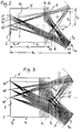
- the outer cold shield 1 a is designed and arranged relative to the inner cold shield 1 i so that the caustics 13 to 17 of the points 18 to 21 of the image plane and from the outer cold shield 1 a through the IR window 8 into the inner cold shield 1 i reflected bundles of rays close up, but not on the IR window 8.
- the radius of curvature of the outer cold aperture 6 a can be optimized using known optical calculation methods. In the embodiment according to FIG. 2, it has the value 27.5.
- FIG. 3 shows a further exemplary embodiment of an infrared radiation detector device according to the invention corresponding to FIG. 2, in which only the detector surface of the detector element 3 and the inner cold aperture 6 i with their opening 7 i are indicated. With 8 the IR window and with 6 a the outer cold aperture is called.
- the pixels 18 ', 19' and 20 ' lie somewhat behind the detector surface.
- the caustics are partly in the IR window 8 and partly in front of and behind the IR window 8 and in front of the inner cold aperture 6 i .
- the maximum beam angle is ⁇ max ⁇ 30 °. This corresponds to an optical aperture of around 0.8.
- the inner cold shield 1 i advantageously has a length z i reduced by up to a factor of 2 compared to the prior art.
- the minimum axial length z o of the inner cold shield is approximately 4d if the maximum total diameter of the flat detector element is 2d.
- the distance z i of the opening 7 i of the inner cold screen 6 i in the invention is only about 2d.
- the inner cold shield can thus be axially shortened by about half compared to the known devices.
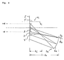
- Fig. 4 shows a further embodiment according to the invention, which is particularly suitable for wide-open systems.
- the inner cold shield 1 i has a radial crown-like or collar-like bottom structure with cooled lateral wall sections 4 'and 5' and with cooled bottom sections 2 'and 2 "which extend radially outwards on both sides, through which the cooled bottom 2 of the inner cold shield as a carrier of the detector element 3 is widened beyond the lateral, axially extending walls 4 'and 5' inner cold screen 6 i is formed here by the free opening cross section of the side wall sections 4 'and 5'.
- the outer cold aperture 6a consists, for example, of a toric mirror surface.
- the side walls 4 'and 5' can form an open cylinder which is closed on one side by the bottom 2.
- the projecting bottom sections 2 'and 2 can form a ring.
- the external cold shield 1 is a configured and arranged relative to the detector element 3 that the outgoing of pixels of the optical image on the surface of the detector element and the outer of the cold plate 1 a reflected beam bundle only fall on cooled surfaces of the internal cold shield 1 i .
- an externally attached cooled light trap can also be used, which is laterally offset from the location of the detector element 3 and, for example, has a structure corresponding to the inner cold shields 1 i according to FIGS 4, which can be chosen freely from the position of the detector element.
- an optimal dewar is designed as follows:
- the outer cold shield 1 a is intended to prevent the detector element 3 from detecting radiation that does not come from the cooled Dewar.
- the detector element 3 should therefore not detect any radiation which lies within undesired solid angle ranges, ie outside the external cold shield opening ratio k a .
- the detector element 3 should "see” in the undesired solid angle areas - via the outer cold shield - exclusively on cooled surfaces and essentially not on itself or on dewar areas outside the internal cold shield 1 i .
- the boundary condition must be met that the dewar lens or the IR window 8 or regions thereof are not imaged on the detector element 3 itself.
- the position of the IR window 8 must be optimized, as is shown above using the exemplary embodiments in FIGS. 1 to 4 and equations (1) to (6).
- an inner cold shield 1 i for an area detector 3 has an inner cold shield 6 i that acts as a baffle and an outer cold shield 1 a has a physical shield as an exit pupil of the upstream IR optics.
- the outer cold shield 1 a is such that the solid angle areas perceived by the detector element 3 between the cold aperture 7 i of the inner cold shield 1 i and the opening 7 a of the outer cold shield 1 a are almost completely reflected on cooled walls of the inner cold shield 1 i .
- the distance z i between the cold shield 6 i of the inner cold shield 1 i is minimized with the optimally smallest possible (effective) inner cold shield opening ratio k i and the detector plane (image plane), while the opening ratio k a of the outer cold shield 6 a is maximized.
- the caustics of the rays emanating from the detector element and reflected by the mirrored inner surface of the outer cold shield lie in the region of the IR window or preferably in the interior of the dewar.
- the mirrored inner surface of the outer cold shield 1 a can be spherical or aspherical. There may be several staggered outer cold shields.
- the physical diaphragm is formed by the outermost cold shield, which is the most distant from the inner cold shield 1 i .
- the remaining outer cold shields and the inner cold aperture form Baffles.
- the edge areas of the inner cold shield are dimensioned (reflectivity, temperature, mechanical dimensions) in such a way that no interfering influences on the detector 3 are caused.
- the IR window 8 of the Dewar can additionally or advantageously be designed as such an internal filter.
- the front of the inner cold baffle 6 i advantageously extends to the inside of the outer outer wall of the Dewar housing.
- the opening 7 i of the inner cold screen 6 i can be roughly tolerated compared to the opening 7 a of the outer cold shield 1 a , which is advantageous since the inner cold screen 6 i is located inside the vacuum vessel (Dewar) which is sealed off from the outside.
- a Dewar with a cold aperture 6 i can be designed in such a way that the entire system can be operated with a changed external opening ratio by simply changing the outer cold shield 1 a .
- the inner cold shield 1 i can also be arranged separately from the detector element 3 externally.
Landscapes
- Physics & Mathematics (AREA)
- General Physics & Mathematics (AREA)
- Optics & Photonics (AREA)
- Spectroscopy & Molecular Physics (AREA)
- Radiation Pyrometers (AREA)
- Photometry And Measurement Of Optical Pulse Characteristics (AREA)
Abstract
Claims (14)
- Dispositif détecteur de rayonnements infrarouges comprenant- un élément détecteur refroidi,- une plaque frigorifique intérieure (1i) qui protège dans une large mesure des rayonnements infrarouges l'élément détecteur refroidi et qui comporte un diaphragme froid intérieur (6i),- un objectif IR servant à former une image infrarouge sur l'élément détecteur (3) et- une plaque frigorifique extérieure (1a) qui est disposée en amont de la plaque frigorifique intérieure (1i) suivant la direction de la lumière et est séparée thermiquement de la plaque frigorifique intérieure et qui comporte un diaphragme froid extérieur (6a),caractérisé- en ce que l'objectif IR comporte des ouvertures (7i, 7a) des diaphragme froid intérieur et diaphragme froid extérieur (6i, 6a), le diaphragme froid extérieur (6a) étant réalisé sous forme d'une pupille de sortie de l'objectif IR,- et en ce qu'une raison d'ouverture de diaphragme froid intérieur ki =zi/2hi, avec zi pour la distance du plan image à l'ouverture de diaphragme froid intérieur (7i) et hi pour la hauteur de bord de l'ouverture de diaphragme froid intérieur (7i) et- une raison d'ouverture de diaphragme froid extérieur ka = za/2ha, avec za pour la distance du plan image à l'ouverture de diaphragme froid extérieur (7a) et ha pour la hauteur de bord du diaphragme froid extérieur (6a)respectent les conditions suivantes :


- Dispositif suivant la revendication 1, caractérisé en ce que, pour un angle maximal de faisceau qmax £ 30° et pour un diamètre total maximal 2d de l'élément détecteur (3), la distance image (zi) à partir de l'ouverture de diaphragme froid intérieur (7i) vaut environ d à 2d.
- Dispositif suivant la revendication 1 ou 2, caractérisé en ce que les plaque frigorifique intérieure et plaque frigorifique extérieure (1i, 1a) sont intégrées avec une ouverture de plaque frigorifique extérieure (7a) formant la pupille de sortie de l'objectif dans un vase sous vide qui est fermé du côté d'entrée de rayonnement par une fenêtre IR (8) qui est disposée en amont de l'ouverture de plaque frigorifique extérieure, zi étant choisi 3 1/2za.
- Dispositif suivant la revendication 1, caractérisé en ce que la raison d'ouverture de diaphragme froid intérieur ki = zi/2hi vaut environ 1,25 à 1,5 et la raison d'ouverture de diaphragme froid extérieur ka = za/2ha vaut environ 2.
- Dispositif suivant la revendication 4, caractérisé en ce que la distance d'ouverture de diaphragme froid intérieur (zi) à partir du plan image vaut environ 25 mm à 40 mm et la distance d'ouverture de diaphragme froid extérieur (za) à partir du plan image vaut environ 40 à 60 mm.
- Dispositif suivant les revendications 4 et 5, caractérisé en ce que la hauteur maximale d'image (d) dans le plan de détecteur vaut environ 10 mm.
- Dispositif suivant l'une des revendications précédentes, caractérisée en ce que les caustiques (13-17, 13'-17') des faisceaux issus des points image (18-21 ; 18'-20') sur la surface de détecteur et réfléchis par la plaque frigorifique extérieure (1a) sont situées, dans la zone de l'ouverture (7i) du diaphragme froid intérieur (6i), à distance des parois (4, 5) de la plaque frigorifique intérieure (1i).
- Dispositif suivant l'une des revendications précédentes, caractérisé en ce qu'il est prévu plusieurs plaques frigorifiques extérieures disposées d'une manière échelonnée l'une derrière l'autre, la plaque frigorifique la plus extérieure formant le diaphragme matériel servant de pupille de sortie et les autres plaques frigorifiques extérieures étant des baffles.
- Dispositif suivant l'une des revendications précédentes, caractérisé en ce que la plaque frigorifique extérieure (1i) formant la pupille de sortie comporte une surface intérieure métallisée sphérique ou asphérique.
- Dispositif suivant la revendication 9, caractérisé en ce que le rayon de courbure de la plaque frigorifique extérieure (1a) vaut environ 22,5 mm.
- Dispositif suivant la revendication 1, caractérisé en ce que la distance (zi) de l'élément détecteur (3) à partir de l'ouverture (7i) de la plaque frigorifique intérieure (6i) vaut environ d, tandis que le fond portant l'élément détecteur (3) comporte des sections de fond radialement extérieures qui font saillie vers l'extérieur au-delà des parois latérales axiales de la plaque frigorifique suivant une forme de couronne ou de collerette et que le diamètre radial de la section de fond vaut environ d.
- Dispositif suivant la revendication 1, caractérisé en ce que la plaque frigorifique intérieure (1i) est disposée de manière externe en étant séparée de la surface de fond (2) de l'élément détecteur (3) et en ce que la plaque frigorifique extérieure (1a) est disposée d'une manière asymétrique par rapport à l'axe optique.
- Dispositif suivant l'une des revendications précédentes. caractérisé en ce qu'un filtre (12) est disposé en amont de l'élément détecteur (3) à l'extérieur des caustiques (13-17, 13'-17').
- Dispositif suivant la revendication 13, caractérisé en ce que la fenêtre IR est réalisée sous forme d'un filtre.
Applications Claiming Priority (3)
| Application Number | Priority Date | Filing Date | Title |
|---|---|---|---|
| DE4303231A DE4303231C2 (de) | 1993-02-04 | 1993-02-04 | Infrarot-Strahlendetektoreinrichtung |
| DE4303231 | 1993-02-04 | ||
| PCT/EP1994/000322 WO1994018530A1 (fr) | 1993-02-04 | 1994-02-04 | Detecteur aux infrarouges |
Publications (2)
| Publication Number | Publication Date |
|---|---|
| EP0634005A1 EP0634005A1 (fr) | 1995-01-18 |
| EP0634005B1 true EP0634005B1 (fr) | 1997-10-22 |
Family
ID=6479657
Family Applications (1)
| Application Number | Title | Priority Date | Filing Date |
|---|---|---|---|
| EP94906220A Expired - Lifetime EP0634005B1 (fr) | 1993-02-04 | 1994-02-04 | Detecteur aux infrarouges |
Country Status (5)
| Country | Link |
|---|---|
| US (1) | US6057550A (fr) |
| EP (1) | EP0634005B1 (fr) |
| AU (1) | AU6002094A (fr) |
| DE (2) | DE4303231C2 (fr) |
| WO (1) | WO1994018530A1 (fr) |
Families Citing this family (10)
| Publication number | Priority date | Publication date | Assignee | Title |
|---|---|---|---|---|
| RU2149365C1 (ru) * | 1998-07-16 | 2000-05-20 | Закрытое акционерное общество "Матричные технологии" | Приемник ик излучения |
| RU2220430C1 (ru) * | 2002-04-04 | 2003-12-27 | Федеральное государственное унитарное предприятие "Центральный научно-исследовательский институт машиностроения" | Оптическая система для ик-области спектра |
| US7598506B2 (en) * | 2006-12-22 | 2009-10-06 | The Boeing Company | Low-temperature adjustable blackbody apparatus |
| US7504609B2 (en) * | 2007-02-07 | 2009-03-17 | Raytheon Company | Phased-array light telescope |
| DE102007035682B4 (de) * | 2007-07-30 | 2018-01-11 | Mbda Deutschland Gmbh | IR-Detektionsvorrichtung |
| FR2936878B1 (fr) * | 2008-10-07 | 2010-12-17 | Onera (Off Nat Aerospatiale) | Systeme d'imagerie grand infrarouge a chambre obscure integrant une lentille |
| US20110080483A1 (en) * | 2009-10-07 | 2011-04-07 | Semi-Conductor Devices - An Elbit Systems-Rafael Partnership | Infra-red imager |
| US9194750B2 (en) | 2009-10-07 | 2015-11-24 | Semi Conductor Devices—Elbit Systems—Rafael Partnership | Infra-red imager |
| US9157806B2 (en) * | 2010-02-18 | 2015-10-13 | Rafael Advanced Defense Systems Ltd. | System and method for changing spectral range of a cryogenically cooled detector |
| US20170034455A1 (en) * | 2015-07-27 | 2017-02-02 | Flir Systems Ab | Detector unit, optical system and thermal camera assembly |
Family Cites Families (17)
| Publication number | Priority date | Publication date | Assignee | Title |
|---|---|---|---|---|
| US3040176A (en) * | 1959-01-26 | 1962-06-19 | Siemens Ag | Hot box detector |
| GB1487493A (en) * | 1975-02-04 | 1977-09-28 | Rank Organisation Ltd | Cold shielding of infra-red radiation detectors |
| US4011452A (en) * | 1975-11-06 | 1977-03-08 | The United States Of America As Represented By The Secretary Of The Air Force | Antinarcissus reflector assembly for infrared detector |
| FR2487512A1 (fr) * | 1980-07-22 | 1982-01-29 | Thomson Csf | Dispositif detecteur de rayonnement infrarouge |
| DE3214269A1 (de) * | 1982-04-17 | 1983-10-20 | Zeiss Carl Fa | Gekuehlte feldoptik fuer infrarotteleskope |
| DD218454A1 (de) * | 1983-03-22 | 1985-02-06 | Univ Dresden Tech | Gesichtsfeldblende fuer gekuehlte infrarotdetektoren |
| JPS6176923A (ja) * | 1984-09-21 | 1986-04-19 | Toshiba Corp | 赤外光測定装置 |
| FR2586292B1 (fr) * | 1985-08-13 | 1989-02-03 | Thomson Csf | Barrette de detecteurs infrarouge comportant un ecran froid a angle de vue constant |
| US4783593A (en) * | 1985-12-26 | 1988-11-08 | General Electric Company | Optical system for wide angle IR imager |
| US4820923A (en) * | 1986-06-19 | 1989-04-11 | Santa Barbara Research Center | Uncooled reflective shield for cryogenically-cooled radiation detectors |
| CA1308283C (fr) * | 1987-02-25 | 1992-10-06 | Mitsubishi Denki Kabushiki Kaisha | Detecteur d'infrarouge |
| DE3716358A1 (de) * | 1987-05-15 | 1988-12-01 | Steinheil Optronik Gmbh | Infrarot-strahlungsdetektor |
| DE3723982A1 (de) * | 1987-07-20 | 1989-02-02 | Steinheil Optronik Gmbh | Infrarot-strahlungsdetektoreinrichtung |
| JPH01299421A (ja) * | 1988-05-27 | 1989-12-04 | Fujitsu Ltd | 赤外線撮像装置 |
| JPH0629778B2 (ja) * | 1988-12-13 | 1994-04-20 | 三菱電機株式会社 | 赤外線光学装置 |
| US4990782A (en) * | 1989-06-23 | 1991-02-05 | Santa Barbara Research Center | Radiation shield for thermoelectrically cooled infrared detectors |
| DE3930828C3 (de) * | 1989-09-14 | 1995-04-20 | Wolfgang Dipl Ing Knappe | Verfahren zur Kompensation der Gehäusetemperatur im Meßsignal eines Pyrometers und Pyrometervorrichtung |
-
1993
- 1993-02-04 DE DE4303231A patent/DE4303231C2/de not_active Expired - Fee Related
-
1994
- 1994-02-04 DE DE59404390T patent/DE59404390D1/de not_active Expired - Fee Related
- 1994-02-04 AU AU60020/94A patent/AU6002094A/en not_active Abandoned
- 1994-02-04 WO PCT/EP1994/000322 patent/WO1994018530A1/fr not_active Ceased
- 1994-02-04 EP EP94906220A patent/EP0634005B1/fr not_active Expired - Lifetime
-
1996
- 1996-06-05 US US08/658,403 patent/US6057550A/en not_active Expired - Fee Related
Also Published As
| Publication number | Publication date |
|---|---|
| US6057550A (en) | 2000-05-02 |
| DE4303231C2 (de) | 1995-02-23 |
| EP0634005A1 (fr) | 1995-01-18 |
| WO1994018530A1 (fr) | 1994-08-18 |
| DE59404390D1 (de) | 1997-11-27 |
| AU6002094A (en) | 1994-08-29 |
| DE4303231A1 (de) | 1994-08-11 |
Similar Documents
| Publication | Publication Date | Title |
|---|---|---|
| DE102011108923B3 (de) | Drei-Spiegel-Anastigmat mit mindestens einem nicht-rotationssymmetrischen Spiegel | |
| DE3879044T2 (de) | Optische anordnung fuer head-up-displays. | |
| EP0639783A1 (fr) | Objectif infrarouge | |
| EP0065159B1 (fr) | Détecteur de mouvement pour contrôler des places | |
| DE3214269C2 (fr) | ||
| EP0144950A2 (fr) | Objectif comportant des surfaces quadratiques pour la formation d'images de microzones | |
| DE3143385C2 (fr) | ||
| WO1994018530A1 (fr) | Detecteur aux infrarouges | |
| DE69505031T2 (de) | Vorrichtung zur Echtzeitlokalisierung von Strahlenquellen | |
| DE69330366T2 (de) | Doublet Kollimationslinse zwischen zwei positiven Linsenelementen | |
| DE60205134T2 (de) | Optische kombination des mehrfeld-cassegrain-typs | |
| DE19632040A1 (de) | Strahlumlenkeinheit zur mehrachsigen Untersuchung in einem Mikroskop, insbesondere Rasterlichtmikroskop | |
| DE3885017T2 (de) | Einrichtung zur selektiven Detektion von Objekten. | |
| DE2639539A1 (de) | Radiometer | |
| DE3716358C2 (fr) | ||
| EP0644445A2 (fr) | Objectif asphérique | |
| CH653446A5 (de) | Spiegellinsenobjektiv von hohem oeffnungsverhaeltnis. | |
| DE69304278T2 (de) | Abtaster für kleine Winkel | |
| EP0515601A1 (fr) | Reflecteur double. | |
| CH657924A5 (de) | Okular. | |
| DE3838168A1 (de) | Optisches bilduebertragungssystem | |
| DE602004008054T2 (de) | Bildgebendes System für den Infrarot-Spektralbereich mit monolithischem Linsen-und Reflektorelement | |
| DE69805792T2 (de) | Optische Architektur für infrarotes Betrachtungssystem | |
| DE1862562U (de) | Periskop. | |
| DE19807093A1 (de) | Achrathermer Reimager |
Legal Events
| Date | Code | Title | Description |
|---|---|---|---|
| PUAI | Public reference made under article 153(3) epc to a published international application that has entered the european phase |
Free format text: ORIGINAL CODE: 0009012 |
|
| AK | Designated contracting states |
Kind code of ref document: A1 Designated state(s): DE FR GB IT NL |
|
| 17P | Request for examination filed |
Effective date: 19950127 |
|
| 17Q | First examination report despatched |
Effective date: 19960905 |
|
| GRAG | Despatch of communication of intention to grant |
Free format text: ORIGINAL CODE: EPIDOS AGRA |
|
| RAP1 | Party data changed (applicant data changed or rights of an application transferred) |
Owner name: BRITISH AEROSPACE PUBLIC LIMITED COMPANY |
|
| GRAH | Despatch of communication of intention to grant a patent |
Free format text: ORIGINAL CODE: EPIDOS IGRA |
|
| GRAH | Despatch of communication of intention to grant a patent |
Free format text: ORIGINAL CODE: EPIDOS IGRA |
|
| GRAA | (expected) grant |
Free format text: ORIGINAL CODE: 0009210 |
|
| AK | Designated contracting states |
Kind code of ref document: B1 Designated state(s): DE FR GB IT NL |
|
| RIN1 | Information on inventor provided before grant (corrected) |
Inventor name: PIETZSCH, KARL Inventor name: SCHWEIGER, JOHANN Inventor name: ERDMANN, MATTHIAS Inventor name: THOMA, CHRISTOPH |
|
| REF | Corresponds to: |
Ref document number: 59404390 Country of ref document: DE Date of ref document: 19971127 |
|
| ITF | It: translation for a ep patent filed | ||
| GBT | Gb: translation of ep patent filed (gb section 77(6)(a)/1977) |
Effective date: 19980121 |
|
| ET | Fr: translation filed | ||
| PLBE | No opposition filed within time limit |
Free format text: ORIGINAL CODE: 0009261 |
|
| STAA | Information on the status of an ep patent application or granted ep patent |
Free format text: STATUS: NO OPPOSITION FILED WITHIN TIME LIMIT |
|
| 26N | No opposition filed | ||
| PGFP | Annual fee paid to national office [announced via postgrant information from national office to epo] |
Ref country code: FR Payment date: 20010111 Year of fee payment: 8 |
|
| PGFP | Annual fee paid to national office [announced via postgrant information from national office to epo] |
Ref country code: GB Payment date: 20010118 Year of fee payment: 8 |
|
| PGFP | Annual fee paid to national office [announced via postgrant information from national office to epo] |
Ref country code: DE Payment date: 20010119 Year of fee payment: 8 |
|
| PGFP | Annual fee paid to national office [announced via postgrant information from national office to epo] |
Ref country code: NL Payment date: 20010129 Year of fee payment: 8 |
|
| REG | Reference to a national code |
Ref country code: GB Ref legal event code: IF02 |
|
| PG25 | Lapsed in a contracting state [announced via postgrant information from national office to epo] |
Ref country code: GB Free format text: LAPSE BECAUSE OF NON-PAYMENT OF DUE FEES Effective date: 20020204 |
|
| PG25 | Lapsed in a contracting state [announced via postgrant information from national office to epo] |
Ref country code: NL Free format text: LAPSE BECAUSE OF NON-PAYMENT OF DUE FEES Effective date: 20020901 |
|
| PG25 | Lapsed in a contracting state [announced via postgrant information from national office to epo] |
Ref country code: DE Free format text: LAPSE BECAUSE OF NON-PAYMENT OF DUE FEES Effective date: 20020903 |
|
| GBPC | Gb: european patent ceased through non-payment of renewal fee |
Effective date: 20020204 |
|
| PG25 | Lapsed in a contracting state [announced via postgrant information from national office to epo] |
Ref country code: FR Free format text: LAPSE BECAUSE OF NON-PAYMENT OF DUE FEES Effective date: 20021031 |
|
| NLV4 | Nl: lapsed or anulled due to non-payment of the annual fee |
Effective date: 20020901 |
|
| REG | Reference to a national code |
Ref country code: FR Ref legal event code: ST |
|
| PG25 | Lapsed in a contracting state [announced via postgrant information from national office to epo] |
Ref country code: IT Free format text: LAPSE BECAUSE OF NON-PAYMENT OF DUE FEES;WARNING: LAPSES OF ITALIAN PATENTS WITH EFFECTIVE DATE BEFORE 2007 MAY HAVE OCCURRED AT ANY TIME BEFORE 2007. THE CORRECT EFFECTIVE DATE MAY BE DIFFERENT FROM THE ONE RECORDED. Effective date: 20050204 |