EP0634060B1 - Selbstausrichtender leiterplattenverbinder hoher dichte - Google Patents
Selbstausrichtender leiterplattenverbinder hoher dichte Download PDFInfo
- Publication number
- EP0634060B1 EP0634060B1 EP93910556A EP93910556A EP0634060B1 EP 0634060 B1 EP0634060 B1 EP 0634060B1 EP 93910556 A EP93910556 A EP 93910556A EP 93910556 A EP93910556 A EP 93910556A EP 0634060 B1 EP0634060 B1 EP 0634060B1
- Authority
- EP
- European Patent Office
- Prior art keywords
- connector
- housing
- pads
- contact
- flexible circuit
- Prior art date
- Legal status (The legal status is an assumption and is not a legal conclusion. Google has not performed a legal analysis and makes no representation as to the accuracy of the status listed.)
- Expired - Lifetime
Links
- 238000003780 insertion Methods 0.000 claims description 12
- 230000037431 insertion Effects 0.000 claims description 12
- 230000000750 progressive effect Effects 0.000 claims description 2
- 238000000429 assembly Methods 0.000 description 29
- 230000000712 assembly Effects 0.000 description 28
- 239000004020 conductor Substances 0.000 description 28
- 125000006850 spacer group Chemical group 0.000 description 8
- 239000002184 metal Substances 0.000 description 6
- 229910052751 metal Inorganic materials 0.000 description 6
- 239000000853 adhesive Substances 0.000 description 5
- 230000001070 adhesive effect Effects 0.000 description 5
- 238000010276 construction Methods 0.000 description 5
- 239000000463 material Substances 0.000 description 5
- 239000000758 substrate Substances 0.000 description 5
- 230000006835 compression Effects 0.000 description 4
- 238000007906 compression Methods 0.000 description 4
- 238000005516 engineering process Methods 0.000 description 4
- 238000007667 floating Methods 0.000 description 4
- 239000002991 molded plastic Substances 0.000 description 4
- 238000004891 communication Methods 0.000 description 3
- 230000008021 deposition Effects 0.000 description 3
- 238000013461 design Methods 0.000 description 3
- 239000003989 dielectric material Substances 0.000 description 3
- 230000014759 maintenance of location Effects 0.000 description 3
- 238000012856 packing Methods 0.000 description 3
- 210000002105 tongue Anatomy 0.000 description 3
- 238000003466 welding Methods 0.000 description 3
- 238000013459 approach Methods 0.000 description 2
- DMFGNRRURHSENX-UHFFFAOYSA-N beryllium copper Chemical compound [Be].[Cu] DMFGNRRURHSENX-UHFFFAOYSA-N 0.000 description 2
- 230000008859 change Effects 0.000 description 2
- 230000007774 longterm Effects 0.000 description 2
- 238000004519 manufacturing process Methods 0.000 description 2
- 230000013011 mating Effects 0.000 description 2
- 238000000034 method Methods 0.000 description 2
- 239000004033 plastic Substances 0.000 description 2
- 230000008569 process Effects 0.000 description 2
- 230000000717 retained effect Effects 0.000 description 2
- 238000003491 array Methods 0.000 description 1
- 230000015572 biosynthetic process Effects 0.000 description 1
- 230000002860 competitive effect Effects 0.000 description 1
- 238000002788 crimping Methods 0.000 description 1
- 239000012777 electrically insulating material Substances 0.000 description 1
- 238000005530 etching Methods 0.000 description 1
- 239000011810 insulating material Substances 0.000 description 1
- 230000003993 interaction Effects 0.000 description 1
- 239000004973 liquid crystal related substance Substances 0.000 description 1
- 230000001681 protective effect Effects 0.000 description 1
- 239000012858 resilient material Substances 0.000 description 1
- 238000004513 sizing Methods 0.000 description 1
- 229910000679 solder Inorganic materials 0.000 description 1
- 239000007787 solid Substances 0.000 description 1
Images


Classifications
-
- H—ELECTRICITY
- H01—ELECTRIC ELEMENTS
- H01R—ELECTRICALLY-CONDUCTIVE CONNECTIONS; STRUCTURAL ASSOCIATIONS OF A PLURALITY OF MUTUALLY-INSULATED ELECTRICAL CONNECTING ELEMENTS; COUPLING DEVICES; CURRENT COLLECTORS
- H01R12/00—Structural associations of a plurality of mutually-insulated electrical connecting elements, specially adapted for printed circuits, e.g. printed circuit boards [PCB], flat or ribbon cables, or like generally planar structures, e.g. terminal strips, terminal blocks; Coupling devices specially adapted for printed circuits, flat or ribbon cables, or like generally planar structures; Terminals specially adapted for contact with, or insertion into, printed circuits, flat or ribbon cables, or like generally planar structures
- H01R12/70—Coupling devices
- H01R12/71—Coupling devices for rigid printing circuits or like structures
- H01R12/712—Coupling devices for rigid printing circuits or like structures co-operating with the surface of the printed circuit or with a coupling device exclusively provided on the surface of the printed circuit
- H01R12/714—Coupling devices for rigid printing circuits or like structures co-operating with the surface of the printed circuit or with a coupling device exclusively provided on the surface of the printed circuit with contacts abutting directly the printed circuit; Button contacts therefore provided on the printed circuit
-
- H—ELECTRICITY
- H01—ELECTRIC ELEMENTS
- H01R—ELECTRICALLY-CONDUCTIVE CONNECTIONS; STRUCTURAL ASSOCIATIONS OF A PLURALITY OF MUTUALLY-INSULATED ELECTRICAL CONNECTING ELEMENTS; COUPLING DEVICES; CURRENT COLLECTORS
- H01R12/00—Structural associations of a plurality of mutually-insulated electrical connecting elements, specially adapted for printed circuits, e.g. printed circuit boards [PCB], flat or ribbon cables, or like generally planar structures, e.g. terminal strips, terminal blocks; Coupling devices specially adapted for printed circuits, flat or ribbon cables, or like generally planar structures; Terminals specially adapted for contact with, or insertion into, printed circuits, flat or ribbon cables, or like generally planar structures
- H01R12/70—Coupling devices
- H01R12/77—Coupling devices for flexible printed circuits, flat or ribbon cables or like structures
- H01R12/79—Coupling devices for flexible printed circuits, flat or ribbon cables or like structures connecting to rigid printed circuits or like structures
-
- H—ELECTRICITY
- H01—ELECTRIC ELEMENTS
- H01R—ELECTRICALLY-CONDUCTIVE CONNECTIONS; STRUCTURAL ASSOCIATIONS OF A PLURALITY OF MUTUALLY-INSULATED ELECTRICAL CONNECTING ELEMENTS; COUPLING DEVICES; CURRENT COLLECTORS
- H01R12/00—Structural associations of a plurality of mutually-insulated electrical connecting elements, specially adapted for printed circuits, e.g. printed circuit boards [PCB], flat or ribbon cables, or like generally planar structures, e.g. terminal strips, terminal blocks; Coupling devices specially adapted for printed circuits, flat or ribbon cables, or like generally planar structures; Terminals specially adapted for contact with, or insertion into, printed circuits, flat or ribbon cables, or like generally planar structures
- H01R12/70—Coupling devices
- H01R12/71—Coupling devices for rigid printing circuits or like structures
- H01R12/72—Coupling devices for rigid printing circuits or like structures coupling with the edge of the rigid printed circuits or like structures
- H01R12/73—Coupling devices for rigid printing circuits or like structures coupling with the edge of the rigid printed circuits or like structures connecting to other rigid printed circuits or like structures
- H01R12/735—Printed circuits including an angle between each other
- H01R12/737—Printed circuits being substantially perpendicular to each other
Definitions
- This invention relates to a self-aligning high-density printed circuit connector system. It relates more particularly, though not exclusively, to connectors for releasably connecting contacts of a flexible or rigid circuit to conductive pads on a printed circuit board and to the interconnection of conductive pads on two such boards.
- flexible printed circuits are employed as electrical jumpers or cables for interconnecting rows of terminal pins or pads of printed circuit boards.
- a connector mounted to one or both ends of the jumper, is formed with a set of electrical receptacles or sockets which are designed to receive the terminal posts or contact the pads on the printed circuit board.
- US-A-3614707 discloses a connector in which the contact areas of the connector are defined by a flexible circuit which is urged toward contact pads on a printed circuit board by spring means.
- the flexible circuit/spring means assembly is however fixed laterally with respect to the connector housing and the printed circuit board is aligned with the connector by engagement between the circuit board and connector.
- the flexible circuit/spring assembly must be accurately located in the housing to ensure accurate alignment of the contact areas of the flexible connector with the contact areas of the printed circuit board.
- the present invention provides a self-aligning high-density connector system.
- a further object is to provide such a connector system which can be formed as an inexpensive structure, is relatively easy and inexpensive to make in quantity and can be mounted to the end of a rigid or flexible circuit without requiring any tool and which can be readily connected to and aligned with contact pads on the face of a printed circuit board.
- One form of the present invention is designed to interconnect two printed circuit (PC) boards and can accommodate up to 63 connectors per centimeter (160 connectors per inch) i.e. 80 connectors on each side of the PC board, i.e. four times the density of existing single row connector technology. Applications with greater densities are expected to be accommodated by the present invention.
- PC printed circuit
- a connector for electrically conductive connection to electrically conductive contact pads of a circuit comprising
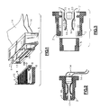
- a molded plastic connector housing 1 consists of first and second housing halves 2 and 3 spaced apart by a spacer 4 of an electrically insulating material.
- the housing halves 2 and 3 are joined together, to form the housing 1, by a support ring 5 which in the assembled connector encompasses the housing halves.
- the support ring may be molded of plastic and may join the housing halves 2 and 3 together in a substantially permanent manner by the use of ultrasonics, adhesives or other means well known to those skilled in the art.
- PC board 6 carries an array of circuit paths 7 terminating at an edge connector portion 8 in a row of electrically conductive contact pads 9.
- a similar row of pads (not shown) is located on the underside of the PC board 6 with the two rows of pads being superimposed as a mirror image of one another.
- the edge connector portion 8 includes recesses 10 which may be used to captively locate the PC board relative to the connector housing 1 by means of pins 11 passing through openings in the housing 1. Although these pins 11 are shown installed in the housing 1, it will be appreciated that in actual use they will be installed only after the edge connector portion 8 is inserted into the housing.
- the first and second housing halves 2 and 3 each include a pair of spaced apart mounting pins 12 (one only being shown for each housing half) by means of which the internal components of the connector, including the spacer 4, are captively held and located within the housing 1.
- the internal components consist of a pair of spring means 13 and a pair of flexible circuits 14 each circuit comprising a flexible substrate carrying a plurality of electrical conductors terminating, at an end of the flexible circuit within the connector, in electrically conductive circuit areas 15 positioned to connect with the pads of the PC board when the connector is attached the edge connector portion of the PC board.
- the flexible circuits 14 extend into a cavity 16 of the housing 1 and are located by the pins 12 which engage openings 21A in the flexible circuits 14 so that the areas 15 of the flexible circuits 14 align with the pads of the PC boards 6 when the edge connector portion 8 thereof is inserted into the connector through an edge connector portion receiving aperture 17 of the housing.
- the flexible circuits 14 are spaced apart by the spacer 4, with their contact areas facing one another, and are biased toward one another by arched portions 18 of the spring means 13 which are located in the housing by engagement of openings in the spring means with the pins 12 between the flexible circuits 14 and the respective housing halves 2 and 3.
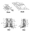
- Each spring means 13 ( Figure 3a) is a comb-like metal structure in which the arched portions 18 are formed in parallel leaf spring portions 19 interconnected at one end thereof by a cross-member 20.
- the cross-member serves to maintain the leaf spring portions 19 in parallel alignment with one another and to located the spring means relative to the contact areas 15 of the flexible circuit and the cavity 16 of the housing 1 by means of holes 21 positioned and sized to accommodate the pins 12.
- Each leaf, of the spring 13 is free to independently deflect to achieve the desired compliance and compensate for variations in board thickness.
- the adhesive and dielectric of the flexible circuit may also be designed to offer selected compliance to individual conductors.
- the holes 21 are sized, together with the corresponding openings of the flexible circuits, to allow a desired amount of float of the spring means 13 and the flexible circuits 14 to ensure proper alignment of the contact areas 15 and the pads for the desired electrical connection of the pads directly with the contact areas 15 under the influence of the resilient arched portions of the spring means 13.
- the interlocking alignment rails 51 align each contact cluster to the mating circuit pattern 9 on the P.C. board. This alignment means ensures that registration of contact areas and pads is provided as described hereinafter.
- each leaf spring 19 is common to four contact areas. It will be appreciated by those skilled in the art that each particular application will determine the number of contact areas common to each leaf spring and that a single leaf spring construction common to all contact areas of each flexible circuit may find application where the resilient compressibility of the substrate of the flexible circuit and/or an intermediate element is provided to ensure the application of a sufficiently even electrical contact producing pressure between the contact areas 15 and the pads throughout the length of the rows of pads.
- the spring means 13 are each captively retained by the pins 12 of the associated housing halves 2 or 3 with the free ends of the leaf springs 19 engaging a housing recess 22 adjacent the aperture 17.
- each of the leaf springs 19 are shaped to define tabs 19a which engage corresponding openings 19b in the end portion of the associated flexible circuit 14 to locate the flexible circuit relative to the leaf spring.
- the contact of the leaf springs and the flexible circuits with the recesses 22 is sufficiently free to allow sufficient floating movement of the spring means 13 with its associated flexible circuit 14 to allow the desired alignment between the contact areas 15 and the pads of the PC boards 6.
- the spacer 4 has recessed areas 23 which prevent the leaf springs 13 and the flexible circuits 14 from being tightly clamped against the first and second housing halves 2 and 3.
- the holes 21 are oval in order to facilitate the desired floating movement.
- the ends of the flexible circuits 14 which are remote from the connector described may be terminated in any conventional manner or may be terminated in a similar connector to that described to provide an interconnect for edge connector pads of two PC boards.
- the engagement of the leaf springs 19 with their attached flexible circuits to the recesses 22 is to ensure that the free ends of the leaf springs 19 and the associated end portions of the flexible circuits 14 do not interfere with the insertion of an edge connector portion of a PC board to the connector.
- the free end portions of the leaf springs 19 and the cross-member 20 serve to provide the contact with the first and second housing halves 2 and 3 required for the application of the necessary spring force by the arched portion of the leaf spring to achieve the desired electrical contact between the contact areas and the pads.
- the spring means 13 may be constructed of a material or coated with a suitable material to provide, with the substrate of the flexible circuits, an impedance desired where the flexible circuit communicates direct with a PC board.
- the connector of the second embodiment includes construction features which function substantially in the same way as the features of the first embodiment of the connectors described with reference to Figures 1-3 for connection to an edge connector portion of a PC board 6 carrying rows of pads as described with reference to the first embodiment.
- the connector of the second embodiment is designed as a self-aligning high-density connector for mounting directly to one face of a further printed circuit board 26 having conductive paths 27 terminating at a connector location 28 in contact pads 29 disposed in parallel rows of pads having a high density center to center spacing of, for example, 0.3 mm (12 mils).
- connector 30 has a molded plastic connector housing 31 consisting of first and second housing halves 32 and 33 spaced apart by a spacer 34 of an electrically insulated material, the housing halves 32 and 33 being joined together to form the housing 31 by a support ring 35 which in the assembled connector encompasses the housing halves.
- the support ring may be molded of plastic and may join the housing halves 32 and 33 together in a substantially permanent manner by the use of adhesives or other means well known to those skilled in the art.
- the first and second housing halves 32 and 33 each include a pair of spaced apart mounting pins 42 (one only being shown for each housing half) by means of which certain internal components of the connector including the spacer 34 are captively held within the housing 31.
- the internal components consists of a pair of spring means 43 each consisting of first and second spring structures 36 and 37 and a pair of flexible circuits 44 each comprising a flexible substrate carrying a plurality of electrical conductors terminating, at one end of the flexible circuit within the connector, in electrically conductive contact areas 45 positioned to connect with the pads 9 of the PC board when the connector is mounted cn the edge connector portion 8 of the PC board 26.
- the flexible circuits 44 extend into a cavity 46 of the housing 31 and are located by the pins 42 which engage openings in the flexible circuits 44 to retain them within the housing 31.
- the flexible circuits 44 are spaced apart by the spacer 34 with their contact areas facing one another and are biased toward one another by arched portions 48 of the first spring structures 36 of the spring means 43 which are located in the housing by engagement with abutment 42a between the flexible circuits 44 and the respective housing halves 32 and 33.
- the arched portions 48 of the spring means 43 overlap the aperture 47 to resiliently bias the contact areas 45 of the flexible circuit into engagement with pads of a printed circuit 6 on which the connector is mounted.
- Each first spring structure 36 ( Figures 4 and 8) is a comb-like metal structure in which the arched portions 48 are formed in parallel leaf springs 49 interconnected at one end of each leaf spring by a cross-member 50 which serves to maintain the leaf springs portions 19 in parallel alignment with one another.
- circuit to board alignment rails 51 At the ends of the cross-member 50 are circuit to board alignment rails 51 the free ends of which are folded to form projections 52 positioned to extend through rectangular openings 53 in the flexible circuit 44 and to engage those openings to maintain the spring means in a desired alignment with the flexible circuit.
- the projections 52 terminate in contact with the conductive contact area carrying face of the flexible circuits adjacent the side edges thereof.
- the projections 52 are designed to mate with alignment tracks (not shown) in PC boards having an edge connector portion 8 to which the connector 30 is to be connected and the rails 51 are resiliently flexible to enable the projections 52 to be urged apart as an edge connector portion of a PC is insert into the aperture 47.
- the projections 52 each overlap the aperture 47 by a minimum of 0.12 mm (5 mils) more than the arched portions of the spring means 43 whereby the pressure otherwise applied by the arched portions is relieved somewhat until the projections 52 engage the tracks. This allows easier floating movement facilitating alignment.
- the spring means 43 are accommodated in cavity 46 of the housing 31 in engagement with recesses corresponding to recesses 22 with tabs 19a at the ends of the leaf springs engaging corresponding rectangular openings (here 54) in one end of the flexible circuits 44 in order to retain the lateral alignment of the flexible circuits 44 with their associated first spring structures 36. Openings 55 locate the flexible circuits 44 in the housing by engagement with pins 42. The shape and sizing of these openings is arranged to permit sufficient float of the flexible circuits 44 together with the spring means 43 relative to the housing to ensure alignment of contact areas of the flexible circuits with contact pads of the print PC boards when the connector is connected thereto.
- the openings 55 are oval to facilitate float in a sideways direction while restricting float longitudinally of the flexible circuits. While the first spring structures 36 are captively housed in the housing 31, these spring structures are permitted a degree of float consistent with the float of the flexible circuits 44 while their alignment with those circuits is ensured by the engagement of the projections 52 with the rectangular openings 53 and tabs 19a with openings 54. Sufficient clearance is provided to ensure unrestricted desired deformation of the first spring structures 36 in the housing.
- Tabs 70 on the first spring structures 36 aligned with the guide rails 51 are arranged to engage openings 71 in tabs 72 formed in the side edges of the flexible circuits 44 to assist in alignment, retention and positioning of the flexible circuits relative to the first spring structures 36.
- the second spring structures 37 which also form part of the spring means 43, have a plurality of leaf springs interconnected at one end thereof by a cross-member 57 defining a pair of openings 58 sized and shaped to encompass the pins 42 while permitting contact aligning float of these second spring structures with the associated end of the flexible circuits 44.
- the end of these leaf springs also include tabs 59 arranged for cooperation with corresponding rectangular openings 60 located in the associated ends of the flexible circuits 44.
- Alignment of the contact areas 61 with the associated contact pads 29 of the further PC board 26 is provided by the allowed float of the second spring structure 37 and the associated ends of the flexible circuits 44 and as a result of the shape of the openings 55 and/or by the provision of a return tuck 62 in the flexible circuits 44 accommodated within the housing 31.
- the second spring structures 37 also include tabs 74 ( Figure 9) to engage openings 75 in the edges of the flexible circuits to assist in alignment, retention and position thereof.
- the spacer (here 34) includes recessed areas to facilitate the desired float of the spring means 43 and the flexible circuits 44.
- the spring means and the flexible circuits include features ensuring their alignment. However, these components are not fixedly connected together and can move independently, within the bounds provided by the alignment arrangement, as they flex in use.
- each leaf spring of each structure 36 and 37 is common to four contact areas.
- the second spring structures 37 are formed so that the cross-member 57 mounted on the pins 42 lies not only transversely of the leaf springs 56 but also in a plane normal or substantially normal to the plane of the leaf springs 56 ( Figure 12).
- leaf springs 56 extend through a side opening of the associated housing half 32 or 33 to enable the associated end portion of the associated flexible circuit 44 with its contact area 61 to lie on top of one face of the further PC board 26 to which the connector is to be attached.
- the leaf springs of one of the second spring structures 37 extend oppositely to and in the same plane as the leaf springs of the other of the second spring structures 37.
- the leaf springs 56 include folded portions 63 adjacent their free end shaped to ensure that the leaf springs 56 resiliently urge the associated contact areas 61 into contact with the contact pads 29 when the connector is attached to the further PC board 26.
- the housing halves 32 and 33 include relieved areas 64 in the openings 65 through which the leaf springs 56 extend to accommodate deflection of these leaf springs in use. It will be appreciated that leaf springs are shaped in order to be resiliently deformed as the connector is attached to the further printed circuit board in order to ensure that the necessary contact of areas and pads as achieved.
- the second spring structures 37 include resilient guide rails 76 including folded portions 77 which pass through slots 78 in the edges of the flexible circuits to engage alignment tracks 79 formed in the further printed circuit board 26.
- the rails 76 extend beyond the folded portions 63 of the leaf springs 56 to relieve spring pressure during alignment and to restore that pressure once alignment is achieved.
- the leaf springs 56 may be folded back upon themselves over the contact areas 61 to be encompassed with those areas 61 substantially under the sidewalls of the housing 31 whereby the housing itself essentially completely covers and protects the region in which the contact areas contact the contact pads of the further PC board 26.
- protective shrouds 67 may be utilized together with an associated compression seal 68 to achieve the same end.
- the leading edge of the circuit in at least the first and second embodiment are positioned under a molded plastic lip to protect it from lifting or buckling during PCB insertion.
- the resilient guide rails 76 are replaced by tapered projections 80 and pass-through slots 78 are replaced by cut-outs 81 which permit the projections 80 to extend through the edges of the flexible circuits 44 for aligning engagement with openings 82 in circuit board 26.
- the tapered feature of the projections 80 permits easy initial alignment of the connector with the circuit board 26 with continued insertion of the projections 80 into the openings 82 precisely aligning the flexible circuit contact areas of the connector 30 with the contact pads of the circuit board 26 by virtue of the engagement of the taper of the projections 80 with the openings 82.
- the alignment features for alignment of the flexible circuit of the connector 30 with an edge connector portion of a circuit board, such as circuit board 6, are substantially the same as those described with reference to the second embodiment.
- the edge of a printed circuit board 6 is illustrated with alignment slots 83 which may be metallic and may be built into the dielectric material, formed by deposition and etching or otherwise attached to the circuit board 6. These slots 83 (one only being shown in Figure 20) engage alignment rails 76 for precisely aligning the edge connector portion of the circuit board 6 with the flexible circuit conductors of the connector 30.
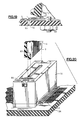
- connector 84 includes housing halves 32 and 33 (somewhat similar to those described with reference to the second embodiment but with the spaced apart mounting pins omitted) are mounted together by means of a mounting ring similar to that described with reference to the first embodiment but not illustrated in the figures relating to the fourth embodiment.
- the internal components of connector 84 consist of a pair of spring means 85 and a pair of flexible circuits 86 held together in alignment with one another by locking buttons 87 and alignment/locking caps 88 with associated alignment facilitating sleds 89 to form a pair of spring/flexible circuit assemblies 90A and 90B.
- the assemblies 90A and 90B are captively held within the connector housing while being free to float within that housing to provide self alignment of the assemblies with the edge connector portion 91 of a circuit board 92 by means of alignment slots 93 (one only being shown in Figures 21 and 22) by virtue of the interaction of the slots 93 with alignment pins 94 formed on the alignment/locking caps 88.
- the connector 84 also includes a substantially elliptical cam 95 extending through the housing to which it is mounted for rotation relative thereto with the axis of the cam traversing the width of the assemblies 90A and 90B. The cam is located between the assemblies for rotation to move both assemblies from the position shown in Figure 21 to the position shown in Figure 22 and allow movement back again under the bias of spring tongues 98 (described below) as desired.
- cam is shown as an elliptical cam
- the cam could be modified so that flats are formed on the cam surface at the extremes of the major axis of the cam to provide a self locating feature which locates the assemblies 90A and 90B in the operating condition shown in Figure 22 by virtue of the resilient pressure of the alignment/locking caps with those flats.
- Other profiles will also be apparent to those skilled in the art.
- the ends of the flexible circuits 86 remote from the locking buttons 87 extend through openings 64 laterally from the connector 84 for connection to components or another circuit board by soldered connection or other form of connection as will be well known to those skilled in the art.
- the cam may be provided with means associated with the housing for locking it in a desired orientation, for example that shown in Figure 22, by locking means (not shown).
- the assemblies 90A, 90B are located in the housing of the connector 84 in mirror image opposition to one another.
- the inwardly facing elevation for assembly 90A is illustrated in Figure 23 wherein the spring means 85 is obscured by the associated flexible circuit 86 and the associated alignment/locking cap 88 which carries an alignment pin 94.
- the spring means of this assembly 90A is captively held in alignment with its flexible circuit 86 by two locking buttons 87 which extend through openings in the spring means and circuit board to lock these members together.
- the locking buttons 87 connect the spring means and the circuit board together close to the ends of these components adjacent the opening 47 of the connector through which the edge connector portion 91 extends for connection to the conductive contacts of the flexible circuits of the connector.
- Each of the spring means 85 defines a plurality of parallel leaf springs 96 at the outer free ends of the outer two of which are alignment openings 97 for receiving locking buttons 87. Remote from the leaf springs 96 are formed a pair of spring tongues 98 which in the forming of the spring 85 are bent out of the plane of the base portion of the spring so that they may pass through grooves 99 (see Figures 27 and 28) of a sled 89.
- the base portion of each spring 85 defines three alignment openings for the passage of alignment pins described below with reference to the alignment/locking caps.
- Each flexible circuit 86 defines a plurality of conductors 101 extending from an edge connector contacting portion 102 to a base portion 103 configured for connection to the surface of another circuit board or other component.
- the flexible circuits 86 each include alignment openings 104 consistent with the alignment openings 97 of the spring means 85 and three alignment openings 105 consistent with the three alignment openings 100 of the spring means 85.
- the sled 89 illustrated in Figures 27 and 28 is illustrated in a form for use when a series of assemblies 90A and 90B are disposed in series along the length of a connector (see for example Figure 29) and to this end each of the semi-circular sleds 89 each define, concentric with the axis of its semi-circular form, a boss 106 designed to engage a corresponding opening in another such sled when located longitudinally with respect to the illustrated sled 89 (see Figure 29).
- the sled illustrated has such a corresponding opening 107 at the end thereof remote from the boss 106.
- Each sled 89 includes transverse grooves 99 sized and shaped to accommodate the spring tongues 98 of a spring means 85 which engage the housing to bias the assembly 90A and 90B toward the release position of Figure 21.
- the sled which is obscured by the rest of the assembly in Figure 23, projects from the rear of the assembly with its semi-circular surface in engagement with a corresponding groove 109 which in conjunction with the sled permits limited rotation of the assemblies 90A and 90B between the operating states illustrated in Figures 21 and 22. At the same time, the sled limits movement of the assemblies transversely of the grooves 109.
- Alignment/locking caps 88 not only provide alignment pins 94 extending into the area of insertion of the edge connector portion 91 but also provide, extending in the opposite direction from pins 94, three pins 110 (only one being shown in Figures 21 and 22) which extend through the alignment openings 100 of the spring means 85, the alignment openings 105 of the flexible circuits 86 and into the alignment openings 108 of the sleds 89.
- the pins 110 engage the openings 108 of the sleds 89 to produce the unified assembly illustrated in Figure 23.
- the pins 110 have an interference fit with openings 108 to positively connect the components of the assemblies 90A and 90B together.
- the connection of the pins 110 with the openings 108 could, alternatively, be by means of an adhesive, ultrasonic welding, etc.
- the locking buttons 87 are preferably constructed of a resilient material to facilitate their introduction through the alignment openings 97 and 104 to connect the leading edges of the spring means and the flexible circuit in relation to one another.
- a connector 84 having nine assemblies 90A and 90B provides a 720 contact connector with 40 contacts for each of the 18 assemblies with 360 contacts per side.
- Each assembly may be approximately 25 millimeters (1 inch) wide having 40 conductors each .25 millimeters (0.010 inch) wide.
- the various assemblies 90A and 90B are each capable of independent floating movement within the connector 84 so that each of these assemblies may be aligned with the corresponding groups of contact pads of the edge connector to which the connector is intended for attachment by virtue of the precise communication between the alignment slots 93 of the edge connector portion and the alignment pins 94 of the various assemblies 90A and 90B.
- the alignment slots 93 each have a tapered entrance to facilitate alignment with the pins. The tapered entrance leads to a parallel locating slot for positive and accurate aligning engagement with the pins 94 of the various assemblies 90A and 90B.
- the sleds 89 are serially spaced with their bosses 106 engaging the next sleds opening 107 with a sufficient longitudinal clearance between them to permit adequate float of the individual assemblies 90A and 90B to provide for the necessary alignment with the contacts of the edge connector contacting portion 102.
- the cam 95 can have progressive actuating surfaces so that the assemblies 90A and 90B are sequentially brought into resilient contacting engagement with the edge connector portion 102.
- the cam profile may be progressively changed to alter the location at which the change of position of the assemblies is achieved or may be changed in a series of steps to achieve the same end.
- each contact may be individually sized to accommodate specific electrical needs, such as power runs, shielding or impedance parameters and still mate with a preexisting circuit board edge connector.
- a further important feature of the fourth embodiment is the ability to protect the leading edge of a edge connector portion of a circuit board during an insertion of that edge into the connector. This results from the freedom of insertion of that edge connector portion as shown in Figure 21 with the subsequent engagement of the connector contacts with the edge connector pads, following insertion, as illustrated in Figure 22.
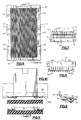
- Figure 31 illustrates an alternative embodiment of assemblies for 90A and 90B for application in various embodiments of the present invention.
- the assembly 111 comprises a flexible dielectric 112 carrying a parallel spaced plurality of conductors 113 (3 only being shown in full with the remainder being shown in part only).
- the spring means is here integrated with the conductors in the form of beryllium-copper conductors 114 to provide resilient connection to the edge connector pads of a circuit board.
- the beryllium-copper conductors also provide resilient bias of the assembly into contact with a surface mount portion of a circuit board.
- the resilient conductor portions 114 and 115 are separated by a relatively flexible loop 116 of the dielectric material on which conductors interconnecting portions 114 and 115 are formed in a somewhat more flexible form than the spring conductors in the portions 114 and 115 thereby to facilitate the self-aligning requirements of the assembly for use in the connector of the present invention.
- the dielectric and conductors of the construction illustrated in Figure 31 are designed to provide, in an integrated assembly, a combination of the resilience of the spring means of the previously described embodiments while at the same time providing the flexible circuit conductor provisions of those embodiments.
- the flexible dielectric 112 carries, on the surface thereof opposite the conductors 113, metal structures 117 which provide the alignment features, in this case of the third embodiment of the invention, and the strain relief interconnection of the assembly with the housing of the connector by connection with the mounting pins 42 while still providing for the desired float of the assembly to provide the self aligning feature of the invention.
- the metal structures 117 may be formed by deposition or made fast to the dielectric material by any other means well known to those skilled in the art.
- the metal structures 117 provide any required lateral stiffness of the structure to ensure the required specific spacing of conductors 113 laterally of the assembly. It will be appreciated by those skilled in the art that the structures 117 are not necessarily made of metal but could be made of any suitable material providing the desired structural requirements are met.
- Figures 32 and 33 illustrate a further form of assembly for use in the present invention in which a conductor carrying a flexible circuit 117 is fast with a spring means 118 to provide the unitary structure suitable for use in the fourth embodiment (in this particular instance) of the present invention.
- the unitary construction may be produced by ultrasonic welding, the use of an adhesive, or the direct formation of the conductors and/or the spring means onto the dielectric by means of deposition etc. to form the unitary structure.
- first and second spring structures are combined into a single structure performing the functions of both the first and second spring structures described.
- first and second spring structures may conveniently be combined into such a single spring structure.
- pads shall be construed to include exposed conductors to which electrical connection is desired.
- the connector may be clamped or supported to the face of the printed circuit board by a wire lock arrangement which is pivotably supported in the housing of the connector and which may be pivoted into engagement with the circuit board, or which may include spring wire features to extend into openings in the circuit board concerned.
- adjustment of contact producing pressure may be provided by a sliding or other cam or wedge movement to increase contact producing pressure when desired e.g. after insertion of the edge connector portion of a circuit board.
- the contacts of the flexible circuit may be etched or stamped from a spring material or built from round spring wire. This approach eliminates the need for an individual spring, stores and applies the necessary contact pressure on demand, provides a wiping contact, compensates for variations in PC board thickness, and the dielectric provides required insulating material and stabilizes individual contacts insuring they maintain their spaced relationship.
- the leading edge of the flexible circuits may be provided with retaining holes which are located by molded in posts. This approach is appropriate with highly flexible circuits.
- the retaining holes are sized to allow sufficient lateral movement as is necessary to align the circuit/spring while preventing the circuit from buckling during PCB insertion.
Landscapes
- Coupling Device And Connection With Printed Circuit (AREA)
Claims (19)
- Verbinder zur elektrisch leitenden Verbindung an elektrisch leitende Kontaktfelder (9) einer Schaltung (6) mita) einem Gehäuse (1),b) einer elastischen flexiblen Schaltungsbaugruppe (13, 14), die unverlierbar von dem Gehäuse (1) gehalten wird, zumindest zum Teil in dem Gehäuse (1) aufgenommen ist und eine flexible Schaltung (14) mit einem Endabschnitt aufweist, der an einer Seite von sich eine Reihe leitender Kontaktflächen (15), die der Reihe von Feldern (9) entsprechen, und eine elastische Federeinrichtung (13) aufweist, um die Flächen (15) federnd in elektrisch leitenden Kontakt mit den Feldern (9) zu bringen, wenn der Verbinder in einer gewünschten Stellung an der Schaltung (6) angebracht ist, dadurch gekennzeichnet, daßc) die elastische flexible Schaltungsbaugruppe (13, 14) in bezug auf das Gehäuse (1) befestigt wird, damit beschränktes seitliches Schwimmen der Baugruppe (13, 14) in bezug auf das Gehäuse (1) zugelassen ist; undd) die elastische flexible Schaltungsbaugruppe (13, 14) eine Ausrichtungseinrichtung (51) aufweist, um ein zusammenwirkendes Merkmal der Schaltung (6) in Eingriff zu nehmen, damit die Registrierung der Kontaktflächen (15) mit den Feldern (9) bewirkt wird, wenn der Verbinder in der gewünschten Stellung an der Schaltung (6) mit hinreichender Genauigkeit angebracht ist, damit gewährleistet ist, daß nur der gewünschte leitende Kontakt zwischen den Kontaktflächen (15) und den Feldern (9) erreicht wird.
- Verbinder nach Anspruch 1, dadurch gekennzeichnet, daß die Baugruppe (13, 14) getrennte flexible Schaltungen (14) und Federeinrichtungen (13) zusammen mit einer Einrichtung (12, 21, 21a, 19a, 19b) aufweist, die die flexible Schaltung (14) lösbar in Ausrichtung mit der Federeinrichtung (13) zwingt, während sie das begrenzte gewünschte Schwimmen zuläßt, wobei die Federeinrichtung (13) die Kontaktflächen (15) federnd in elektrisch leitenden Kontakt mit den Feldern (9) drängt, wenn der Verbinder in einer gewünschten Stellung an der Schaltung (6) angebracht wird.
- Verbinder (30) nach Anspruch 1 oder 2, dadurch gekennzeichnet, daßa) die Federeinrichtung (43) eine erste Vielzahl von miteinander verbundenen parallelen Blattfedern (19) aufweist, von denen jede ein bogenförmiges Merkmal (48) aufweist, um das federnde Drängen zu schaffen, wobei jede Blattfeder (19) zumindest einer Fläche (15) entspricht;b) das Gehäuse (31) eine Öffnung (47) zum Anordnen und Aufnehmen eines Randabschnitts der Schaltung (6) aufweist, die die Kontaktfelder (9) in einer Reihe trägt, die sich entlang des Randabschnitts erstreckt, und die Kontaktflächen (15) elektrisch leitend die Felder (9) kontaktieren, wenn der Randabschnitt in die Öffnung (47) eingesetzt ist;c) die erste Vielzahl von Blattfedern (19) in dem Gehäuse (31) aufgenommen ist, und die Federeinrichtung (43) eine zweite Vielzahl von parallelen Blattfedern (56) aufweist, die sich von dem Gehäuse (31) aus erstrekken, wobei jede zumindest einer Kontaktfläche (45) der flexiblen Schaltung (44) entspricht;d) die flexible Schaltung (44) sich von dem Gehäuse (31) aus erstreckt, wobei die Kontaktflächen (45) angeordnet sind, um federnd von der zweiten Vielzahl von Blattfedern (56) in Kontakt mit einer Reihe leitender Kontakte (27) an einer Seite einer Leiterplatte (26) gedrängt zu werden, wenn der Verbinder (30) an der Leiterplatte (26) in einer Stellung angebracht ist, wo die Kontaktflächen (45) die leitenden Kontakte (27) überlagern, um dadurch eine elektrisch leitende Verbindung zwischen entsprechenden leitenden Kontakten (27) und Kontaktfelder (29) durch direkte Verbindung mit den Kontaktflächen (45) zu erleichtern, und mite) einer Einrichtung (66) zum Anbringen des Gehäuses (31) an die Leiterplatte (26) in einer derartigen Stellung, wobeif) der Abschnitt der flexiblen Schaltung (44), der sich von dem Gehäuse (31) aus erstreckt, lösbar in Ausrichtung mit der Federeinrichtung (43) durch eine weitere Ausrichtungseinrichtung (77) der Federeinrichtung (43) gezwungen ist, wobei in die weitere Ausrichtungseinrichtung (77) ein zusammenwirkendes Merkmal (79) der Leiterplatte (26) in Eingriff nimmt, damit die Flächen (45) mit den leitenden Kontakten (27) registrieren, wenn der Verbinder (30) an die Leiterplatte (26) in der Stellung mit hinreichender Genauigkeit angebracht wird, damit gewährleistet ist, daß nur der gewünschte leitende Kontakt zwischen den Flächen (45) und den leitenden Kontakten (27) erreicht wird.
- Verbinder nach einem der Ansprüche 1 bis 3, dadurch gekennzeichnet, daßa) der Verbinder zur Verbindung an einen Randabschnitt der Schaltung (6) dient, wobei er gegenüberliegende Seiten aufweist, die jeweils eine Reihe der Kontaktfelder (9) tragen;b) das Gehäuse (1) eine gesonderte elastische flexible Schaltungsbaugruppe (13, 14) aufnimmt, die zu jeder Reihe von Feldern (9) gehört,c) die Einrichtung (12, 21, 21a) zum Schaffen des Schwimmens, das begrenzte gewünschte Schwimmen für jede Baugruppe (13, 14) schafft, undd) jede der Baugruppen (13, 14) auf die gleiche Weise lösbar gezwungen und elastisch gedrängt angeordnet ist.
- Verbinder nach Anspruch 3, dadurch gekennzeichnet, daßa) die Leiterplatte (26) zwei Reihen (29) leitender Kontakte (27) aufweist, und eine gesonderte Federeinrichtung (43) zu jeder Reihe (29) leitender Kontakte (27) gehört;b) jede Federeinrichtung (43) eine zweite Vielzahl paralleler Blattfedern (56) aufweist, wobei jede einen bogenförmigen Abschnitt (63) aufweist und mindestens einer der Kontaktflächen (45) entspricht;c) eine gesondert flexible Schaltung (44) für jede Reihe (29) leitender Kontakte (27) vorgesehen ist, wobei jede flexible Schaltung (44) auf die gleiche Weise lösbar gezwungen und elastisch gedrängt angeordnet ist; undd) die Blattfedern (56) von der zweiten Vielzahl paralleler Federn (37) in entgegengesetzte Richtungen von dem Gehäuse (31) im großen und ganzen senkrecht zu der Richtung der Aufnahme des Randabschnitts in die Öffnung (17) verlaufen, und jede zweite Vielzahl paralleler Federn (37) angeordnet ist, um gewünschte Kontaktflächen (45) in Kontakt mit dazugehörigen leitenden Kontakten (27) zu drängen, wenn der Verbinder (30) an der Leiterplatte (26) angebracht ist, wobei die Kontaktflächen (45) die leitenden Kontakte (27) überlagern.
- Verbinder nach Anspruch 2, dadurch gekennzeichnet, daß die Ausrichtungseinrichtung (51) elastische Vorsprünge (51) der Federeinrichtung (13) aufweist, die angeordnet sind, um mit der flexiblen Schaltung (14) zusammenzuwirken, damit die flexible Schaltung (14) zumindest in einer Richtung parallel zu dem Verlauf der Reihe von Feldern (9) lösbar gezwungen wird, wenn der Rand in die Öffnung (17) eingesetzt wird, und um mit einem Ausrichtungsmerkmal der Schaltung (6) zusammenzuwirken, damit die Registrierung gewährleistet ist.
- Verbinder nach Anspruch 6, dadurch gekennzeichnet, daß die Vorsprünge (51) die Ausrichtung schaffen, während sie erlauben, daß von dem bogenförmigen Abschnitt (18) ausgeübter Druck vermieden wird, außer wenn die Registrierung erreicht ist.
- Verbinder nach Anspruch 3, dadurch gekennzeichnet, daß die weitere Ausrichtungseinrichtung (77) mit der Leiterplatte (26) zusammenwirkt, um zuzulassen, daß von den bogenförmigen Abschnitten (63) ausgeübter Druck vermieden wird, außer wenn die Registrierung erreicht ist.
- Verbinder nach Anspruch 2, dadurch gekennzeichnet, daß die Ausrichtung der Federeinrichtung (13) und der flexiblen Schaltung (14) durch Abschnitte (19a) der Federeinrichtung (13) erreicht wird, die angeordnet sind, um Öffnungen (19b) in der flexiblen Schaltung (14) in Eingriff zu nehmen.
- Verbinder nach Anspruch 3, dadurch gekennzeichnet, daß die Ausrichtungseinrichtung Endabschnitte (59) der Blattfedern (56) umfassen, die angeordnet sind, um Öffnungen (60) in der flexiblen Schaltung (44) in Eingriff zu nehmen, um lösbar die flexible Schaltung (44) seitlich der Blattfedern (56) zu zwingen.
- Verbinder nach Anspruch 1, dadurch gekennzeichnet, daß die Ausrichtungseinrichtung Öffnungen (21, 21a) in der Baugruppe (13, 14) aufweist, um Stifte (12) in dem Gehäuse (1) mit hinreichendem Abstand zu umschließen, um das gewünschte Schwimmen zu erlauben.
- Verbinder (84) nach Anspruch 1, dadurch gekennzeichnet, daß die Baugruppe (90A, 90B) in dem Gehäuse zwischen einer ersten Stellung, die das Einsetzen der Felder (9) in den Verbinder erleichtert und einer zweiten Stellung bewegbar ist, in der die Flächen (15) und die Felder (9) elastisch in den leitenden Kontakt gedrängt werden.
- Verbinder (84) nach Anspruch 12, dadurch gekennzeichnet, daß eine Einrichtung (95) vorgesehen ist, um die Baugruppe (90A, 90B) von der ersten in die zweite Stellung zu bewegen.
- Verbinder (84) nach Anspruch 13, dadurch gekennzeichnet, daß die Bewegungseinrichtung ein Nocken (95) ist.
- Verbinder (84) nach Anspruch 12, dadurch gekennzeichnet, daß die Baugruppe (90A, 90B) eine flexible Schaltung (86), eine Federeinrichtung (85), die an der flexiblen Schaltung (86) angebracht ist, um sich damit zu bewegen, und eine Dreheinrichtung (89, 109) aufweist, die eine Drehbewegung der Baugruppe (90A, 90B) zwischen der ersten und der zweiten Stellung erleichtert.
- Verbinder (84) nach Anspruch 15, dadurch gekennzeichnet, daß die Dreheinrichtung (89, 109) ein Bogenglied (89) aufweist, das an der Baugruppe (90A, 90B) angebracht ist, das von einem gebogenen Merkmal (109) des Gehäuses (32, 33) unterstützt wird, das ausgelegt ist, um das Schwimmen und die Drehbewegung zuzulassen, während die Baugruppe (90A, 90B) in dem Gehäuse (32, 33) gehalten wird.
- Verbinder nach Anspruch 1, dadurch gekennzeichnet, daß die Baugruppe (111) eine Einheitsstruktur hat.
- Verbinder nach Anspruch 17, dadurch gekennzeichnet, daß die leitenden Kontaktflächen (114) das elastische Drängen schaffen.
- Verbinder (84) nach Anspruch 14, dadurch gekennzeichnet, daß die Nocke (95) eine flache, eine Stellung anordnende Nocke, eine progressive Kontur, ein elliptisches Profil oder aufeinanderfolgende Funktionsprofile aufweist.
Applications Claiming Priority (3)
| Application Number | Priority Date | Filing Date | Title |
|---|---|---|---|
| US07/861,119 US5240420A (en) | 1992-03-31 | 1992-03-31 | Self-aligning high-density printed circuit connector |
| PCT/US1993/002892 WO1993020597A1 (en) | 1992-03-31 | 1993-03-26 | Self-aligning high-density printed circuit connector |
| US861119 | 1997-05-21 |
Publications (3)
| Publication Number | Publication Date |
|---|---|
| EP0634060A1 EP0634060A1 (de) | 1995-01-18 |
| EP0634060A4 EP0634060A4 (de) | 1997-03-12 |
| EP0634060B1 true EP0634060B1 (de) | 1999-02-10 |
Family
ID=25334931
Family Applications (1)
| Application Number | Title | Priority Date | Filing Date |
|---|---|---|---|
| EP93910556A Expired - Lifetime EP0634060B1 (de) | 1992-03-31 | 1993-03-26 | Selbstausrichtender leiterplattenverbinder hoher dichte |
Country Status (4)
| Country | Link |
|---|---|
| US (2) | US5240420A (de) |
| EP (1) | EP0634060B1 (de) |
| DE (1) | DE69323486T2 (de) |
| WO (1) | WO1993020597A1 (de) |
Families Citing this family (50)
| Publication number | Priority date | Publication date | Assignee | Title |
|---|---|---|---|---|
| US5240420A (en) * | 1992-03-31 | 1993-08-31 | Research Organization For Circuit Knowledge | Self-aligning high-density printed circuit connector |
| JPH06231837A (ja) * | 1993-02-04 | 1994-08-19 | Murata Mfg Co Ltd | コネクタ |
| US5531615A (en) * | 1993-08-05 | 1996-07-02 | The Whitaker Corporation | Coplanar computer docking apparatus |
| US5427533A (en) * | 1993-11-02 | 1995-06-27 | Northrop Grumman Corporation | Zero insertion force connector |
| EP0687035B1 (de) * | 1994-06-07 | 2002-11-27 | The Whitaker Corporation | Kartenstecke mit Ausziehvorrichtung und deren flexiblen Druckschaltung mit Kabelbaum |
| US5421738A (en) * | 1994-06-29 | 1995-06-06 | Miraco, Inc. | High-density printed circuit connector with pivotable spring |
| US5721007A (en) * | 1994-09-08 | 1998-02-24 | The Whitaker Corporation | Process for low density additive flexible circuits and harnesses |
| USD368071S (en) | 1994-09-22 | 1996-03-19 | Tvm, Inc. | Perpendicular mounting hybrid modular electrical power connector |
| US5609496A (en) * | 1994-11-15 | 1997-03-11 | Micropolis Pte Ltd. | Air-tight connector assembly |
| JPH10509835A (ja) * | 1994-11-30 | 1998-09-22 | ミネソタ・マイニング・アンド・マニュファクチュアリング・カンパニー | 多層積層構造の電気コネクタアセンブリ及び製造方法 |
| US5676559A (en) * | 1995-07-06 | 1997-10-14 | The Whitaker Corporation | Zero insertion force (ZIF) electrical connector |
| US5769668A (en) * | 1996-03-08 | 1998-06-23 | Robinson Nugent, Inc. | Module alignment apparatus for an electrical connector |
| US5873739A (en) * | 1996-05-14 | 1999-02-23 | Miraco, Inc. | Direct circuit to circuit stored energy connector |
| US5730619A (en) * | 1996-07-01 | 1998-03-24 | General Motors Corporation | Externally locked connector |
| US5707241A (en) * | 1996-07-01 | 1998-01-13 | General Motors Corporation | Slide locking connector |
| GB9722330D0 (en) * | 1997-10-22 | 1997-12-17 | Amp Great Britain | Electrical connector for flexible film |
| US5971806A (en) * | 1997-11-26 | 1999-10-26 | Berg Technology, Inc. | Electrical connector for connecting conductor areas of a flexible circuit with associated conductor pads of a circuit board |
| US5954536A (en) * | 1998-03-27 | 1999-09-21 | Molex Incorporated | Connector for flat flexible circuitry |
| USD410894S (en) * | 1998-04-24 | 1999-06-15 | Elcon Products International Company | Electrical connector housing |
| USD411173S (en) | 1998-04-24 | 1999-06-22 | Elcon Products International | Electrical connector housing |
| USD408361S (en) * | 1998-04-24 | 1999-04-20 | Elcon Products International Company | Electrical connector housing |
| USD418479S (en) * | 1998-07-14 | 2000-01-04 | Hon Hai Precision Ind. Co., Ltd. | Electrical connector |
| USD425865S (en) * | 1998-07-14 | 2000-05-30 | Hon Hai Precision Ind. Co., Ltd. | Electrical connector |
| US6089925A (en) * | 1998-10-06 | 2000-07-18 | The Whitaker Corporation | Modular electrical connector having electrical contact modules |
| JP2000150030A (ja) * | 1998-11-17 | 2000-05-30 | Japan Aviation Electronics Industry Ltd | ケーブルコネクタ及びその結線方法 |
| EP1196966B1 (de) | 1999-04-23 | 2003-12-10 | SonionMicrotronic A/S | Verbinder und verfahren für eine lötfreie verbindung zwischen einer gedruckten, festen, hauptschaltplatte und deren leiter |
| US6193544B1 (en) | 1999-11-04 | 2001-02-27 | Jae Electronics, Inc. | Flexible circuit service connector |
| JP2003142183A (ja) * | 2001-11-01 | 2003-05-16 | Fujitsu Component Ltd | コンタクトモジュール、コネクタおよびコンタクトモジュールの製造方法 |
| DE10203150A1 (de) * | 2002-01-28 | 2003-07-31 | Harting Electro Optics Gmbh & | Steckverbinder mit verschiebbaren Kontaktelementen |
| DE10227156A1 (de) * | 2002-06-18 | 2004-01-08 | Harting Electro-Optics Gmbh & Co. Kg | Steckverbinder mit verschiebbarer Steckerteil-Aufnahme |
| USD492256S1 (en) | 2002-08-08 | 2004-06-29 | Hon Hai Precision Ind. Co., Ltd. | Electrical connector |
| EP1458059A1 (de) * | 2003-03-13 | 2004-09-15 | Fred Peng | Verbindungsanordnung zur elektrischen Verbindung einer flexiblen Leiterplatte mit einer Leiterplatte |
| TW566700U (en) * | 2003-03-19 | 2003-12-11 | Benq Corp | Connection device |
| DE20310734U1 (de) * | 2003-07-12 | 2003-10-23 | HARTING Electro-Optics GmbH & Co. KG, 32339 Espelkamp | Steckvorrichtung zur Verbindung von Leiterplatten |
| DE102004008014A1 (de) * | 2004-02-19 | 2005-09-08 | Robert Bosch Gmbh | Direktsteckverbindung mit Kabelendhülse |
| WO2008076813A2 (en) | 2006-12-13 | 2008-06-26 | Panduit Corp. | Communication jack having layered plug interface contacts |
| US7438582B2 (en) * | 2006-12-22 | 2008-10-21 | Amphenol Corporation | Flexible circuit connector assembly |
| JP4753055B2 (ja) * | 2008-05-21 | 2011-08-17 | Smc株式会社 | スタッキングコネクタ |
| CN201323341Y (zh) * | 2008-12-11 | 2009-10-07 | 富士康(昆山)电脑接插件有限公司 | 线缆连接器组件 |
| CN101924300B (zh) * | 2009-06-15 | 2013-03-06 | Smc株式会社 | 电连接器以及电连接器组装体 |
| US8641452B2 (en) | 2011-03-22 | 2014-02-04 | Panduit Corp. | Communication jack having an insulating element connecting a spring element and a spring end of a contact element |
| TWI413315B (zh) * | 2011-08-30 | 2013-10-21 | Wistron Corp | 連接器及其電子裝置 |
| US8840415B2 (en) * | 2011-10-05 | 2014-09-23 | Tyco Electronics Corporation | Power cable connector |
| US8979562B2 (en) * | 2012-07-25 | 2015-03-17 | Fci Americas Technology Llc | Bus bar lockingly attached to a housing of an electrical connector and its end inserted between rows of power contacts of the electrical connector |
| DE102016205476B4 (de) * | 2016-04-01 | 2019-08-01 | Continental Automotive Gmbh | Steckeraufnahme und Stecker für eine elektrische Steckverbindung und elektrische Steckverbindung |
| TWM544145U (zh) * | 2016-08-12 | 2017-06-21 | P-Two Ind Inc | 連接器模組 |
| US10811794B2 (en) * | 2018-01-11 | 2020-10-20 | Te Connectivity Corporation | Card edge connector system |
| US10637171B1 (en) * | 2019-03-15 | 2020-04-28 | Aptiv Technologies Limited | Electrical connector |
| CN111009758B (zh) * | 2019-10-30 | 2021-07-30 | 中航光电科技股份有限公司 | 一种大容差浮动连接器及连接器组件 |
| JP7438076B2 (ja) * | 2020-10-01 | 2024-02-26 | ヒロセ電機株式会社 | 相手電気コネクタ及び電気コネクタ組立体 |
Family Cites Families (24)
| Publication number | Priority date | Publication date | Assignee | Title |
|---|---|---|---|---|
| US3158421A (en) * | 1961-12-04 | 1964-11-24 | Gen Dynamics Corp | Electrical connector for a printed circuit board and cable |
| DE1802130A1 (de) * | 1968-10-09 | 1970-04-23 | Siemens Ag | Vielfachstecker |
| US3941448A (en) * | 1974-07-29 | 1976-03-02 | E. I. Du Pont De Nemours & Company | Connector block |
| NL173804C (nl) * | 1977-06-30 | 1984-03-01 | Du Pont | Contactinrichting voor een ketenplaat. |
| US4172626A (en) * | 1978-06-22 | 1979-10-30 | Amp Incorporated | Connector clip for connecting cable conductors to circuit board conductors |
| US4225205A (en) * | 1979-01-15 | 1980-09-30 | Aries Electronics, Inc. | Electrical connector for terminating a flat conductor cable |
| JPS56116282A (en) * | 1980-02-19 | 1981-09-11 | Sharp Kk | Electronic part with plural terminals |
| DE3245521C2 (de) * | 1982-12-09 | 1986-05-07 | Preh, Elektrofeinmechanische Werke Jakob Preh Nachf. Gmbh & Co, 8740 Bad Neustadt | Mehrpolige Randverbinderleiste |
| US4509098A (en) * | 1983-02-24 | 1985-04-02 | At&T Bell Laboratories | Electrical printed wiring circuit board construction |
| US4597617A (en) * | 1984-03-19 | 1986-07-01 | Tektronix, Inc. | Pressure interconnect package for integrated circuits |
| US4587596A (en) * | 1984-04-09 | 1986-05-06 | Amp Incorporated | High density mother/daughter circuit board connector |
| US4581495A (en) * | 1984-05-02 | 1986-04-08 | Buscom Systems Inc. | Modular telephone housing |
| US4583800A (en) * | 1984-08-20 | 1986-04-22 | Advanced Circuit Technology, Inc. | Self-aligning electrical connection assembly |
| US4621305A (en) * | 1984-08-22 | 1986-11-04 | General Motors Corporation | Header connector and attachment |
| US4602317A (en) * | 1984-12-13 | 1986-07-22 | Gte Communication Systems Corporation | Printed wiring board connector |
| JPH0665090B2 (ja) * | 1985-09-06 | 1994-08-22 | Fpcコネクタ | |
| US4740867A (en) * | 1987-03-26 | 1988-04-26 | Advanced Circuit Technology, Inc. | Printed circuit connection system |
| US4911643A (en) * | 1988-10-11 | 1990-03-27 | Beta Phase, Inc. | High density and high signal integrity connector |
| US4913656A (en) * | 1989-04-07 | 1990-04-03 | Rogers Corporation | Electrical connector |
| US4969824A (en) * | 1989-07-28 | 1990-11-13 | Amp Incorporated | Electrical connector |
| NL9000087A (nl) * | 1990-01-12 | 1991-08-01 | Du Pont Nederland | Hybride-connector met contactorganen in de vorm van flexibele geleiderfolie. |
| US5009605A (en) * | 1990-03-13 | 1991-04-23 | Hughes Aircraft Company | Flat electrical connector assembly with precisely aligned soldering traces |
| US5171154A (en) * | 1991-11-06 | 1992-12-15 | Amp Incorporated | High density backplane connector |
| US5240420A (en) * | 1992-03-31 | 1993-08-31 | Research Organization For Circuit Knowledge | Self-aligning high-density printed circuit connector |
-
1992
- 1992-03-31 US US07/861,119 patent/US5240420A/en not_active Expired - Lifetime
-
1993
- 1993-03-26 DE DE69323486T patent/DE69323486T2/de not_active Expired - Fee Related
- 1993-03-26 US US08/037,351 patent/US5306160A/en not_active Expired - Fee Related
- 1993-03-26 EP EP93910556A patent/EP0634060B1/de not_active Expired - Lifetime
- 1993-03-26 WO PCT/US1993/002892 patent/WO1993020597A1/en not_active Ceased
Also Published As
| Publication number | Publication date |
|---|---|
| US5240420A (en) | 1993-08-31 |
| EP0634060A1 (de) | 1995-01-18 |
| DE69323486T2 (de) | 1999-06-24 |
| WO1993020597A1 (en) | 1993-10-14 |
| US5306160A (en) | 1994-04-26 |
| EP0634060A4 (de) | 1997-03-12 |
| DE69323486D1 (de) | 1999-03-25 |
Similar Documents
| Publication | Publication Date | Title |
|---|---|---|
| EP0634060B1 (de) | Selbstausrichtender leiterplattenverbinder hoher dichte | |
| EP0622871B1 (de) | Elektrische Verbinderanordnung mit vorgespannten Abschirmplatten | |
| US4881901A (en) | High density backplane connector | |
| EP0854549B1 (de) | Oberflächenmontierbarer Verbinder mit integrierter Leiterplattenanordnung | |
| US5664968A (en) | Connector assembly with shielded modules | |
| KR100339766B1 (ko) | 커넥터조립체 | |
| EP0838101B1 (de) | Elektrische verbinder | |
| US6592407B2 (en) | High-speed card edge connector | |
| KR20020021385A (ko) | 모듈방식 전기 커넥터 및 커넥터시스템 | |
| EP3890119B1 (de) | Abschirmkomponente zur verwendung mit einem modularen elektrischen verbinder zur reduzierung des übersprechens | |
| EP0767977B1 (de) | Leiterplattenverbinder hoher dichte mit drehbaren federn | |
| US7059907B2 (en) | Modular electrical connector | |
| US5472349A (en) | Surface mountable board edge connector | |
| US6053757A (en) | Printed circuit board edge card connector having two non-redundant rows of contacts | |
| JP2001266980A (ja) | 電気コネクタおよびその製造方法 | |
| US6682369B1 (en) | Electrical connector having retention system for precisely mounting plural boards therein | |
| US6899565B2 (en) | Electrical connector having a holddown for ground connection | |
| US20020115318A1 (en) | Electrical connector and circuit with center ground plane | |
| US20030008570A1 (en) | Electrical contact for LGA and BGA electrical packages | |
| CN117954913A (zh) | 位于触头列之间的接地屏蔽件 | |
| US5908330A (en) | Platelike member | |
| US20250087943A1 (en) | Electrical connector and connector assembly thereof with improved shielding effect | |
| US20250105550A1 (en) | Connector frame unit and connector frame strip for chicklets | |
| JP2026508580A (ja) | 接地シールドコンタクト部材 | |
| CN117954914A (zh) | 用于优化接地电流的接触件和屏蔽配置 |
Legal Events
| Date | Code | Title | Description |
|---|---|---|---|
| PUAI | Public reference made under article 153(3) epc to a published international application that has entered the european phase |
Free format text: ORIGINAL CODE: 0009012 |
|
| 17P | Request for examination filed |
Effective date: 19940926 |
|
| AK | Designated contracting states |
Kind code of ref document: A1 Designated state(s): DE FR GB |
|
| A4 | Supplementary search report drawn up and despatched |
Effective date: 19950708 |
|
| AK | Designated contracting states |
Kind code of ref document: A4 Designated state(s): DE FR GB |
|
| 17Q | First examination report despatched |
Effective date: 19971013 |
|
| GRAG | Despatch of communication of intention to grant |
Free format text: ORIGINAL CODE: EPIDOS AGRA |
|
| GRAG | Despatch of communication of intention to grant |
Free format text: ORIGINAL CODE: EPIDOS AGRA |
|
| GRAH | Despatch of communication of intention to grant a patent |
Free format text: ORIGINAL CODE: EPIDOS IGRA |
|
| GRAH | Despatch of communication of intention to grant a patent |
Free format text: ORIGINAL CODE: EPIDOS IGRA |
|
| GRAA | (expected) grant |
Free format text: ORIGINAL CODE: 0009210 |
|
| AK | Designated contracting states |
Kind code of ref document: B1 Designated state(s): DE FR GB |
|
| REF | Corresponds to: |
Ref document number: 69323486 Country of ref document: DE Date of ref document: 19990325 |
|
| ET | Fr: translation filed | ||
| PLBE | No opposition filed within time limit |
Free format text: ORIGINAL CODE: 0009261 |
|
| STAA | Information on the status of an ep patent application or granted ep patent |
Free format text: STATUS: NO OPPOSITION FILED WITHIN TIME LIMIT |
|
| 26N | No opposition filed | ||
| PGFP | Annual fee paid to national office [announced via postgrant information from national office to epo] |
Ref country code: FR Payment date: 20010302 Year of fee payment: 9 |
|
| PGFP | Annual fee paid to national office [announced via postgrant information from national office to epo] |
Ref country code: GB Payment date: 20010306 Year of fee payment: 9 |
|
| PGFP | Annual fee paid to national office [announced via postgrant information from national office to epo] |
Ref country code: DE Payment date: 20010307 Year of fee payment: 9 |
|
| REG | Reference to a national code |
Ref country code: GB Ref legal event code: IF02 |
|
| PG25 | Lapsed in a contracting state [announced via postgrant information from national office to epo] |
Ref country code: GB Free format text: LAPSE BECAUSE OF NON-PAYMENT OF DUE FEES Effective date: 20020326 |
|
| PG25 | Lapsed in a contracting state [announced via postgrant information from national office to epo] |
Ref country code: DE Free format text: LAPSE BECAUSE OF NON-PAYMENT OF DUE FEES Effective date: 20021001 |
|
| GBPC | Gb: european patent ceased through non-payment of renewal fee |
Effective date: 20020326 |
|
| PG25 | Lapsed in a contracting state [announced via postgrant information from national office to epo] |
Ref country code: FR Free format text: LAPSE BECAUSE OF NON-PAYMENT OF DUE FEES Effective date: 20021129 |
|
| REG | Reference to a national code |
Ref country code: FR Ref legal event code: ST |