EP0634224A1 - Bague d'étanchéité pour pistolet de peinture portable - Google Patents
Bague d'étanchéité pour pistolet de peinture portable Download PDFInfo
- Publication number
- EP0634224A1 EP0634224A1 EP94111252A EP94111252A EP0634224A1 EP 0634224 A1 EP0634224 A1 EP 0634224A1 EP 94111252 A EP94111252 A EP 94111252A EP 94111252 A EP94111252 A EP 94111252A EP 0634224 A1 EP0634224 A1 EP 0634224A1
- Authority
- EP
- European Patent Office
- Prior art keywords
- shaft
- seal
- conical
- shaft seal
- sealing surface
- Prior art date
- Legal status (The legal status is an assumption and is not a legal conclusion. Google has not performed a legal analysis and makes no representation as to the accuracy of the status listed.)
- Granted
Links
- 239000003973 paint Substances 0.000 title claims abstract description 24
- 238000007789 sealing Methods 0.000 claims abstract description 28
- 230000004323 axial length Effects 0.000 claims abstract description 4
- 230000013011 mating Effects 0.000 claims description 5
- 230000006835 compression Effects 0.000 claims description 2
- 238000007906 compression Methods 0.000 claims description 2
- -1 polytetrafluorethylene Polymers 0.000 claims description 2
- 229920001343 polytetrafluoroethylene Polymers 0.000 claims description 2
- 239000012858 resilient material Substances 0.000 claims description 2
- 230000014759 maintenance of location Effects 0.000 abstract 1
- 239000000463 material Substances 0.000 description 5
- 239000012530 fluid Substances 0.000 description 4
- 230000000717 retained effect Effects 0.000 description 4
- 238000012856 packing Methods 0.000 description 2
- 239000004809 Teflon Substances 0.000 description 1
- 229920006362 Teflon® Polymers 0.000 description 1
- 230000003993 interaction Effects 0.000 description 1
- 230000007246 mechanism Effects 0.000 description 1
- 238000012986 modification Methods 0.000 description 1
- 230000004048 modification Effects 0.000 description 1
- 238000010422 painting Methods 0.000 description 1
- 239000004033 plastic Substances 0.000 description 1
- BFKJFAAPBSQJPD-UHFFFAOYSA-N tetrafluoroethene Chemical compound FC(F)=C(F)F BFKJFAAPBSQJPD-UHFFFAOYSA-N 0.000 description 1
- 238000003466 welding Methods 0.000 description 1
Images


Classifications
-
- B—PERFORMING OPERATIONS; TRANSPORTING
- B05—SPRAYING OR ATOMISING IN GENERAL; APPLYING FLUENT MATERIALS TO SURFACES, IN GENERAL
- B05B—SPRAYING APPARATUS; ATOMISING APPARATUS; NOZZLES
- B05B7/00—Spraying apparatus for discharge of liquids or other fluent materials from two or more sources, e.g. of liquid and air, of powder and gas
- B05B7/02—Spray pistols; Apparatus for discharge
- B05B7/12—Spray pistols; Apparatus for discharge designed to control volume of flow, e.g. with adjustable passages
- B05B7/1209—Spray pistols; Apparatus for discharge designed to control volume of flow, e.g. with adjustable passages the controlling means for each liquid or other fluent material being manual and interdependent
Definitions
- This invention pertains to the field of portable painting equipment, more particularly to portable paint guns referred to as high volume low pressure or HVLP type paint guns.
- portable paint guns referred to as high volume low pressure or HVLP type paint guns.
- HVLP type paint guns have been characterized by relatively complex and costly sealing mechanisms to prevent the escape of pressurized air from the interior of such guns.
- the present invention provides an improved apparatus for preventing the escape of pressurized air in a simple and efficient structure.
- Figure 1 is a right side elevation view of the present invention with parts cut away and with movable parts shown in an OFF position.
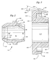
- Figure 2 is an enlarged side elevation detail of the shaft seal of the present invention.
- Figure 3 is an enlarged side elevation detail of an air valve for the gun of the present invention.
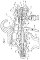
- Figure 4 is a fragmentary right side elevation view as seen in Figure 1 with movable parts in an intermediate position.
- Figure 5 is a fragmentary right side elevation view with movable parts in an ON position.
- a portable paint gun 10 may be seen.
- Gun 10 has a handle 12 which is preferably hollow, and through which compressed air can pass when connected to a source of compressed air via fitting 14.
- Gun 10 further has a paint cup 16 having a siphon tube 18 to draw paint out of paint cup 16 in operation.
- Gun 10 further has a trigger 20 pivotably mounted to a gun body 22 via a trigger pin 24.
- Gun 10 further has an air cap 26 retained by a locking ring 28 on body 22.
- An air cap spring 30 is preferably secured to a detent plate 32, as for example, by spot welding.
- Detent plate 32 preferably has projections 34, 36 which are retained respectively in slots 38, 40 to prevent rotation of plate 32.
- Plate 32 preferably has a cruciform opening interdigitated with projections on plate 32 (not shown) which are received in mating recesses (not shown) in air cap 26. The detents in plate 32 and recesses in cap 26 cooperate to hold cap 26 in one of three predetermined positions to provide for control of the paint pattern in a manner well known.
- Gun 10 further has a fluid nozzle 42 which cooperates with a needle 44 to form a needle or paint valve 46 to control the flow of paint or other material delivered by gun 10.
- a needle packing nut 48 is preferably threaded into body 22 to compress needle packing 50 against needle 44.
- Gun 10 also has an air passageway 52 in communication with a plenum 54 surrounding fluid nozzle 42.
- Plenum 54 is in communication with recess 56 in air cap 26.
- Trigger 20 is in contact with an air valve shaft 58 surrounding needle 44 and carrying an air valve 60.
- An air plug 62 is preferably threaded into body 22 to close off an alternative inlet to passageway 52.
- gun 10 is arranged for "non-bleeder” operation. By interchanging plug 62 with fitting 14, and supplying air directly to passageway 52, gun 10 would be configured for "bleeder” operation.
- Valve 60 is retained on shaft 58 by a retaining ring 64 on one side of valve 60 and by a flange 66 on the other side of valve 60. Valve 60 is urged toward a mating seat 68 by an air valve spring 70. Air valve spring 70 is also in contact with a shaft seal 72. Shaft seal 72 seals shaft 58 against a material adjustment housing 74 threaded into gun body 22. A needle spring 76 is retained by a material adjustment knob 78 threaded on housing 74 and spring 76 urges needle 44 forward against nozzle 42 to maintain needle valve 46 in a closed position.
- a bushing 79 preferably formed of plastic serves as a guide and air seal around shaft 58 and holds shaft 58 and needle 44 in alignment during assembly and operation of gun 10. It is to be understood that bushing 79 need not be an "air-tight" seal since it only needs to prevent air leakage along shaft 58 when valve 60 is in the intermediate and ON positions.
- Seal 72 has a mediate portion 80 having a radially outwardly projecting flange 82 and a generally cylindrical interior recess 84 located radially inwardly of the flange 82. Seal 72 further has a first conical rim 86 extending axially in a first direction away from flange 82 with a shallow conical taper from a relatively thicker cross-section 88 proximal of the flange 82 to a relatively thinner cross-section 90 distal of flange 82. Shaft seal 72 further has a first extension 92 of the generally cylindrical interior recess 84 with extension 92 located radially inwardly of surface 86.
- Seal 72 further has a second conical rim 94 extending axially in a second direction opposite the first direction away from flange 82 and further has a second extension 96 of the generally cylindrical interior recess 84 extending axially along and radially inward of rim 94.
- Rim 94 of seal 72 has a conical inner surface 98 extending from the second extension 96 of the generally cylindrical interior recess 84 to a cylindrical shaft sealing surface 100 which is located axially distal of the flange 82 in the second direction.
- Rim 94 also has a tapered sealing surface 102 having an external conical taper adapted for contacting and interfitting with a mating correspondingly tapered bore or chamfer 104 in element 74 of paint gun 10 such that shaft seal 72 prevents the passage of air between the control shaft 58 and the shaft sealing surface 100 and also from between the sealing surface 102 and the tapered bore 104 when pressurized air is present in chamber 106.
- first conical rim 86 is sized to mate in an interference fit with cylindrical compression spring 70 to retain seal 72 on spring 70 when gun 10 is disassembled. It is further to be understood that spring 70 acts against flange 82 to urge seal 72 in the second direction with respect to the control shaft 58.
- the first conical rim 86 tapers from 0.228 inches diameter to 0.311 inches diameter and the spring 70 has an internal diameter of 0.316 inches.
- the tapered sealing surface 102 of conical rim 94 preferably has a taper substantially equal to a taper of the conical inner surface 98 providing a constant cross-sectional thickness of rim 94 between surfaces 98 and 102.
- the cylindrical interior recess 84, along with its extensions 92, 96 preferably has a diameter substantially greater than the diameter of the control shaft around which the seal 72 is located such that there is a radial clearance between shaft 58 and recess 84, together with its extensions 92, 96.
- the shaft sealing surface 100 preferably has an axial length that is relatively short with respect to the axial length of the overall shaft seal 72 (e.g. less than ten percent) such that the resistance to relative axial movement between the control shaft 58 and the seal 72 is minimized.
- surface 100 is 0.025 inches long while seal 72 is 0.365 inches long overall.
- Surfaces 98, 102 and 104 each preferably have a conical taper of 30 degrees.
- pressure from spring 70 forces seal 72 against the tapered bore or chamfer 104 in the material adjustment housing 74 creating an airtight seal.
- Axial force or pressure generated by spring 70 is transferred to a radial force by the interaction of surfaces 102, 104 thus urging surface 100 against shaft 58 (making use of the conical flexibility of rim 94), forming an airtight seal.
- seal 72 wears at surface 100, seal 72 is permitted to move axially in the second direction as urged by spring 70 to maintain sufficient pressure to insure sealing between shaft 58, seal 72 and housing 74.
- Valve 60 has a generally cylindrical axially extending hub portion 110 having a through bore 112, a radially outwardly projecting support portion 114 mounted on the hub portion 110, and a generally conical outer rim portion 116 extending coaxially with hub portion 110 and mounted on support portion 114 radially outwardly of hub portion 110.
- Rim portion 116 has a tapered sealing surface 118 adapted for matingly interfitting with a tapered valve seating surface 120 in the body 22 of gun 10.
- Valve 60 further has an axial recess 122 located in a region radially inward of the tapered sealing surface of rim portion 116.
- the hub portion 110 of valve 60 has a first shoulder 124 and a second shoulder 126 for locating the valve in first and second axial directions on shaft 58.
- Shoulder 124 is held by retaining ring 64 and shoulder 126 is held by flange 66 on shaft 58.
- Both seal 72 and valve 60 are preferably formed of a relatively resilient material such as virgin polytetrafluorethylene as sold under the trademark TEFLON by EI Dupont de Nemours Co.
- the material of valve 60 is preferably homogeneous with the rim portion 116 being relatively flexible with respect to the hub and support portions 110, 114 such that sealing surface 118 conforms to the seating surface 120 when valve 60 is drawn against the seating surface 120.
- Surface 118 preferably has an external conical angle 128 of 16 degrees, while seating surface 120 preferably has an internal conical angle 130 of 18 degrees.
- Rim portion 116 provides a "forgiving" alignment between seal 60 and seating surface 120.
- the flexibility of rim portion 116 allows the tapered sealing surface 118 to conform to radial and axial misalignment between seal 60 and gun body 22. Because angle 130 is greater than angle 128, a leading edge 132 of the sealing surface 118 will contact surface 120 first.
- hub portion 110 and support portion 114 are relatively rigid with respect to rim portion 116 which is relatively conically flexible and provides a secondary seal area along surface 118 distal of leading edge 132, thus compensating for creep or cold flow of lip portion 116 during the operating lifetime of gun 10.
- the rigidity of support portion 114 also provides a radial clearance protection of rim portion 116 to reduce the possibility of damage during storage and handling of valve 60 prior to assembly into gun 10.
- the gun is shown in an OFF position with both the paint or needle valve 46 and air valve 60 in a closed position.
- Paint valve 46 is closed when needle 44 is its forwardmost position and is contacting the interior of fluid nozzle 42.
- Air valve 60 is in the closed position when control shaft 58 is in the forwardmost or closed position.
- retracting trigger 20 from the OFF or closed position shown in Figure 1 to an intermediate position as shown in Figure 4 will move control shaft 58, but not needle 44, thus opening passageway 52 to the source of pressurized air by moving air valve 60 away from seating surface 120 permitting the passage of air therethrough.
- Further progression of trigger 20 from the position shown at Figure 4 to the position shown in Figure 5 will move the control shaft 58 axially within seal 72 further in the second direction causing the control shaft to drive needle 44 against spring 76 opening the needle valve 46.
- both the paint valve 46 and the air valve 60 are in the OFF position.
- the air valve 60 is in the ON position while the paint valve 46 remains in the OFF position.
- both the paint valve 46 and the air valve 60 are in the ON position.
Landscapes
- Nozzles (AREA)
Applications Claiming Priority (5)
| Application Number | Priority Date | Filing Date | Title |
|---|---|---|---|
| US553432 | 1990-07-20 | ||
| US07/553,432 US5078323A (en) | 1990-07-20 | 1990-07-20 | Air valve for portable paint gun |
| US07/560,744 US5050804A (en) | 1990-08-03 | 1990-08-03 | Shaft seal for portable paint gun |
| US560744 | 1990-08-03 | ||
| EP19910111954 EP0467334B1 (fr) | 1990-07-20 | 1991-07-17 | Pistolet de peinture portable |
Related Parent Applications (1)
| Application Number | Title | Priority Date | Filing Date |
|---|---|---|---|
| EP91111954.3 Division | 1991-07-17 |
Publications (2)
| Publication Number | Publication Date |
|---|---|
| EP0634224A1 true EP0634224A1 (fr) | 1995-01-18 |
| EP0634224B1 EP0634224B1 (fr) | 1997-01-02 |
Family
ID=27070337
Family Applications (2)
| Application Number | Title | Priority Date | Filing Date |
|---|---|---|---|
| EP94111252A Expired - Lifetime EP0634224B1 (fr) | 1990-07-20 | 1991-07-17 | Bague d'étanchéité pour pistolet de peinture portable |
| EP19910111954 Expired - Lifetime EP0467334B1 (fr) | 1990-07-20 | 1991-07-17 | Pistolet de peinture portable |
Family Applications After (1)
| Application Number | Title | Priority Date | Filing Date |
|---|---|---|---|
| EP19910111954 Expired - Lifetime EP0467334B1 (fr) | 1990-07-20 | 1991-07-17 | Pistolet de peinture portable |
Country Status (5)
| Country | Link |
|---|---|
| EP (2) | EP0634224B1 (fr) |
| JP (1) | JP2506516B2 (fr) |
| CA (2) | CA2047014C (fr) |
| DE (2) | DE69123985T2 (fr) |
| DK (2) | DK0634224T3 (fr) |
Cited By (7)
| Publication number | Priority date | Publication date | Assignee | Title |
|---|---|---|---|---|
| WO2000024521A3 (fr) * | 1998-10-22 | 2000-08-17 | Jim Lindsay Limited | Procede et appareil de pulverisation |
| US8944351B2 (en) | 2011-05-06 | 2015-02-03 | Saint-Gobain Abrasives, Inc. | Paint cup assembly with an outlet valve |
| US9162240B2 (en) | 2004-12-16 | 2015-10-20 | Saint-Gobain Abrasives, Inc./Saint-Gobain Abrasie | Liquid container system for a spray gun |
| US9586220B2 (en) | 2011-06-30 | 2017-03-07 | Saint-Gobain Abrasives, Inc. | Paint cup assembly |
| US10035156B2 (en) | 2006-06-20 | 2018-07-31 | Saint-Gobain Abrasives, Inc. | Liquid supply assembly |
| US10882064B2 (en) | 2011-12-30 | 2021-01-05 | Saint-Gobain Abrasives, Inc./Saint-Gobain Abrasifs | Convertible paint cup assembly with air inlet valve |
| US11040360B2 (en) | 2006-06-20 | 2021-06-22 | Saint-Gobain Abrasives, Inc. | Liquid supply assembly |
Families Citing this family (2)
| Publication number | Priority date | Publication date | Assignee | Title |
|---|---|---|---|---|
| DE69509373T2 (de) * | 1994-02-18 | 1999-08-26 | Itw Ltd. | Spritzpistole mit dauerhaft befestigtem Sprühkopf |
| DE10218871A1 (de) * | 2002-04-26 | 2003-11-13 | Degussa | Verfahren zur Imprägnierung von porösen mineralischen Substraten |
Citations (3)
| Publication number | Priority date | Publication date | Assignee | Title |
|---|---|---|---|---|
| GB799991A (en) * | 1956-03-09 | 1958-08-13 | Adams Ltd L | A control valve |
| US4560109A (en) * | 1982-06-29 | 1985-12-24 | Iwata Air Compressor Mfg. Co., Ltd. | Shaft sealing device for sliding portion of needle valve in paint spray gun |
| WO1991011644A1 (fr) * | 1990-02-05 | 1991-08-08 | Itw Limited | Structure d'emballage d'aiguille |
Family Cites Families (4)
| Publication number | Priority date | Publication date | Assignee | Title |
|---|---|---|---|---|
| US1875438A (en) * | 1932-09-06 | Faucet gasket | ||
| FR587897A (fr) * | 1924-10-24 | 1925-04-25 | Soupapes et procédé pour leur fabrication | |
| US2888207A (en) * | 1954-12-20 | 1959-05-26 | Bell & Gossett Co | Spray gun |
| US4154403A (en) * | 1976-08-27 | 1979-05-15 | Tricentrol Manufacturing Pty. Limited | Spraygun |
-
1991
- 1991-07-15 CA CA 2047014 patent/CA2047014C/fr not_active Expired - Fee Related
- 1991-07-15 CA CA002165693A patent/CA2165693C/fr not_active Expired - Fee Related
- 1991-07-17 DE DE1991623985 patent/DE69123985T2/de not_active Expired - Fee Related
- 1991-07-17 DE DE1991616454 patent/DE69116454T2/de not_active Expired - Fee Related
- 1991-07-17 DK DK94111252T patent/DK0634224T3/da active
- 1991-07-17 EP EP94111252A patent/EP0634224B1/fr not_active Expired - Lifetime
- 1991-07-17 EP EP19910111954 patent/EP0467334B1/fr not_active Expired - Lifetime
- 1991-07-17 DK DK91111954T patent/DK0467334T3/da active
- 1991-07-18 JP JP3178399A patent/JP2506516B2/ja not_active Expired - Lifetime
Patent Citations (3)
| Publication number | Priority date | Publication date | Assignee | Title |
|---|---|---|---|---|
| GB799991A (en) * | 1956-03-09 | 1958-08-13 | Adams Ltd L | A control valve |
| US4560109A (en) * | 1982-06-29 | 1985-12-24 | Iwata Air Compressor Mfg. Co., Ltd. | Shaft sealing device for sliding portion of needle valve in paint spray gun |
| WO1991011644A1 (fr) * | 1990-02-05 | 1991-08-08 | Itw Limited | Structure d'emballage d'aiguille |
Cited By (13)
| Publication number | Priority date | Publication date | Assignee | Title |
|---|---|---|---|---|
| US6793157B1 (en) | 1998-10-22 | 2004-09-21 | Jim Lindsay Limited | Method and apparatus for spraying |
| WO2000024521A3 (fr) * | 1998-10-22 | 2000-08-17 | Jim Lindsay Limited | Procede et appareil de pulverisation |
| US9162240B2 (en) | 2004-12-16 | 2015-10-20 | Saint-Gobain Abrasives, Inc./Saint-Gobain Abrasie | Liquid container system for a spray gun |
| US11040360B2 (en) | 2006-06-20 | 2021-06-22 | Saint-Gobain Abrasives, Inc. | Liquid supply assembly |
| US12064783B2 (en) | 2006-06-20 | 2024-08-20 | Saint-Gobain Abrasives, Inc. | Liquid supply assembly |
| US11679399B2 (en) | 2006-06-20 | 2023-06-20 | Saint-Gobain Abrasives, Inc. | Liquid supply assembly |
| US11548018B1 (en) | 2006-06-20 | 2023-01-10 | Saint-Gobain Abrasives, Inc. | Liquid supply assembly |
| US10035156B2 (en) | 2006-06-20 | 2018-07-31 | Saint-Gobain Abrasives, Inc. | Liquid supply assembly |
| US8998018B2 (en) | 2011-05-06 | 2015-04-07 | Saint-Gobain Abrasives, Inc. | Paint cup assembly with an extended ring |
| US9335198B2 (en) | 2011-05-06 | 2016-05-10 | Saint-Gobain Abrasives, Inc. | Method of using a paint cup assembly |
| US8944351B2 (en) | 2011-05-06 | 2015-02-03 | Saint-Gobain Abrasives, Inc. | Paint cup assembly with an outlet valve |
| US9586220B2 (en) | 2011-06-30 | 2017-03-07 | Saint-Gobain Abrasives, Inc. | Paint cup assembly |
| US10882064B2 (en) | 2011-12-30 | 2021-01-05 | Saint-Gobain Abrasives, Inc./Saint-Gobain Abrasifs | Convertible paint cup assembly with air inlet valve |
Also Published As
| Publication number | Publication date |
|---|---|
| JPH04227083A (ja) | 1992-08-17 |
| DK0467334T3 (da) | 1996-02-12 |
| DE69116454D1 (de) | 1996-02-29 |
| CA2047014C (fr) | 1998-05-05 |
| DE69123985D1 (de) | 1997-02-13 |
| EP0634224B1 (fr) | 1997-01-02 |
| CA2047014A1 (fr) | 1992-01-21 |
| CA2165693C (fr) | 1998-05-19 |
| EP0467334A3 (en) | 1992-07-08 |
| EP0467334A2 (fr) | 1992-01-22 |
| DK0634224T3 (da) | 1997-01-20 |
| DE69123985T2 (de) | 1997-07-03 |
| EP0467334B1 (fr) | 1996-01-17 |
| CA2165693A1 (fr) | 1992-01-21 |
| JP2506516B2 (ja) | 1996-06-12 |
| DE69116454T2 (de) | 1996-09-05 |
Similar Documents
| Publication | Publication Date | Title |
|---|---|---|
| US5078323A (en) | Air valve for portable paint gun | |
| US5050804A (en) | Shaft seal for portable paint gun | |
| US6019294A (en) | Interchangeable feed airspray/HVLP spray gun | |
| JP3178842B2 (ja) | 冷凍装置サービスアダプタ | |
| US5209501A (en) | Needle packing assembly | |
| US4441629A (en) | Compressed gas powered caulking gun | |
| US4830281A (en) | Spray tip with seal ejector | |
| US7546959B2 (en) | Cleaning nozzle | |
| US4426062A (en) | Fluid flow control valves | |
| EP0634224B1 (fr) | Bague d'étanchéité pour pistolet de peinture portable | |
| US8006923B2 (en) | Smooth bore nozzle with adjustable bore | |
| US4560109A (en) | Shaft sealing device for sliding portion of needle valve in paint spray gun | |
| US5294053A (en) | Airless spray head with improved orifice tip mounting | |
| US4959159A (en) | Ball and socket attachment for fluid spray gun plunger | |
| US4941614A (en) | Nozzle for spraying equipment | |
| CA1139804A (fr) | Tete de vaporisation | |
| US5379938A (en) | Seal for airless spray gun | |
| EP1306593B1 (fr) | Aiguille de valve, utilisée en particulier dans la pulvérisation de liquides de revêtement | |
| US4958769A (en) | Compressed O-ring spray gun needle valve seal | |
| US20050093295A1 (en) | Hydraulic swivel fitting for a dispensing apparatus | |
| CA2117269C (fr) | Joint a air ameliore pour pistolet de peinture | |
| US4149381A (en) | Single hand operated tool | |
| US5829680A (en) | Toolless airless spray head | |
| US20220169495A1 (en) | High pressure fuel nozzle leak stop assembly | |
| EP2167858B1 (fr) | Joint gonflant longitudinal pour pistolet de pulvérisation |
Legal Events
| Date | Code | Title | Description |
|---|---|---|---|
| PUAI | Public reference made under article 153(3) epc to a published international application that has entered the european phase |
Free format text: ORIGINAL CODE: 0009012 |
|
| AC | Divisional application: reference to earlier application |
Ref document number: 467334 Country of ref document: EP |
|
| AK | Designated contracting states |
Kind code of ref document: A1 Designated state(s): CH DE DK FR GB IT LI NL |
|
| 17P | Request for examination filed |
Effective date: 19950116 |
|
| RIN1 | Information on inventor provided before grant (corrected) |
Inventor name: GUNDERSON, RICHARD W. Inventor name: STEINBERG, TIMOTHY D. Inventor name: SVENDSEN, JOHN M. |
|
| GRAG | Despatch of communication of intention to grant |
Free format text: ORIGINAL CODE: EPIDOS AGRA |
|
| GRAH | Despatch of communication of intention to grant a patent |
Free format text: ORIGINAL CODE: EPIDOS IGRA |
|
| 17Q | First examination report despatched |
Effective date: 19960529 |
|
| GRAH | Despatch of communication of intention to grant a patent |
Free format text: ORIGINAL CODE: EPIDOS IGRA |
|
| GRAA | (expected) grant |
Free format text: ORIGINAL CODE: 0009210 |
|
| ITF | It: translation for a ep patent filed | ||
| AC | Divisional application: reference to earlier application |
Ref document number: 467334 Country of ref document: EP |
|
| AK | Designated contracting states |
Kind code of ref document: B1 Designated state(s): CH DE DK FR GB IT LI NL |
|
| REG | Reference to a national code |
Ref country code: CH Ref legal event code: EP |
|
| REG | Reference to a national code |
Ref country code: DK Ref legal event code: T3 |
|
| ET | Fr: translation filed | ||
| REF | Corresponds to: |
Ref document number: 69123985 Country of ref document: DE Date of ref document: 19970213 |
|
| REG | Reference to a national code |
Ref country code: CH Ref legal event code: NV Representative=s name: ISLER & PEDRAZZINI AG |
|
| PGFP | Annual fee paid to national office [announced via postgrant information from national office to epo] |
Ref country code: GB Payment date: 19970708 Year of fee payment: 7 |
|
| PGFP | Annual fee paid to national office [announced via postgrant information from national office to epo] |
Ref country code: DK Payment date: 19970715 Year of fee payment: 7 |
|
| PGFP | Annual fee paid to national office [announced via postgrant information from national office to epo] |
Ref country code: NL Payment date: 19970731 Year of fee payment: 7 |
|
| PGFP | Annual fee paid to national office [announced via postgrant information from national office to epo] |
Ref country code: CH Payment date: 19970805 Year of fee payment: 7 |
|
| PLBE | No opposition filed within time limit |
Free format text: ORIGINAL CODE: 0009261 |
|
| STAA | Information on the status of an ep patent application or granted ep patent |
Free format text: STATUS: NO OPPOSITION FILED WITHIN TIME LIMIT |
|
| 26N | No opposition filed | ||
| PGFP | Annual fee paid to national office [announced via postgrant information from national office to epo] |
Ref country code: FR Payment date: 19980709 Year of fee payment: 8 |
|
| PG25 | Lapsed in a contracting state [announced via postgrant information from national office to epo] |
Ref country code: GB Free format text: LAPSE BECAUSE OF NON-PAYMENT OF DUE FEES Effective date: 19980717 |
|
| PG25 | Lapsed in a contracting state [announced via postgrant information from national office to epo] |
Ref country code: LI Free format text: LAPSE BECAUSE OF NON-PAYMENT OF DUE FEES Effective date: 19980731 Ref country code: DK Free format text: LAPSE BECAUSE OF NON-PAYMENT OF DUE FEES Effective date: 19980731 Ref country code: CH Free format text: LAPSE BECAUSE OF NON-PAYMENT OF DUE FEES Effective date: 19980731 |
|
| PG25 | Lapsed in a contracting state [announced via postgrant information from national office to epo] |
Ref country code: NL Free format text: LAPSE BECAUSE OF NON-PAYMENT OF DUE FEES Effective date: 19990201 |
|
| GBPC | Gb: european patent ceased through non-payment of renewal fee |
Effective date: 19980717 |
|
| REG | Reference to a national code |
Ref country code: CH Ref legal event code: PL |
|
| NLV4 | Nl: lapsed or anulled due to non-payment of the annual fee |
Effective date: 19990201 |
|
| PG25 | Lapsed in a contracting state [announced via postgrant information from national office to epo] |
Ref country code: FR Free format text: THE PATENT HAS BEEN ANNULLED BY A DECISION OF A NATIONAL AUTHORITY Effective date: 19990731 |
|
| REG | Reference to a national code |
Ref country code: DK Ref legal event code: EBP |
|
| REG | Reference to a national code |
Ref country code: FR Ref legal event code: ST |
|
| PGFP | Annual fee paid to national office [announced via postgrant information from national office to epo] |
Ref country code: DE Payment date: 20010716 Year of fee payment: 11 |
|
| PG25 | Lapsed in a contracting state [announced via postgrant information from national office to epo] |
Ref country code: DE Free format text: LAPSE BECAUSE OF NON-PAYMENT OF DUE FEES Effective date: 20030201 |
|
| PG25 | Lapsed in a contracting state [announced via postgrant information from national office to epo] |
Ref country code: IT Free format text: LAPSE BECAUSE OF NON-PAYMENT OF DUE FEES;WARNING: LAPSES OF ITALIAN PATENTS WITH EFFECTIVE DATE BEFORE 2007 MAY HAVE OCCURRED AT ANY TIME BEFORE 2007. THE CORRECT EFFECTIVE DATE MAY BE DIFFERENT FROM THE ONE RECORDED. Effective date: 20050717 |