EP0634551A2 - Crémone - Google Patents
Crémone Download PDFInfo
- Publication number
- EP0634551A2 EP0634551A2 EP94106020A EP94106020A EP0634551A2 EP 0634551 A2 EP0634551 A2 EP 0634551A2 EP 94106020 A EP94106020 A EP 94106020A EP 94106020 A EP94106020 A EP 94106020A EP 0634551 A2 EP0634551 A2 EP 0634551A2
- Authority
- EP
- European Patent Office
- Prior art keywords
- espagnolette
- bolt
- cross
- section
- end region
- Prior art date
- Legal status (The legal status is an assumption and is not a legal conclusion. Google has not performed a legal analysis and makes no representation as to the accuracy of the status listed.)
- Granted
Links
Images



Classifications
-
- E—FIXED CONSTRUCTIONS
- E05—LOCKS; KEYS; WINDOW OR DOOR FITTINGS; SAFES
- E05C—BOLTS OR FASTENING DEVICES FOR WINGS, SPECIALLY FOR DOORS OR WINDOWS
- E05C9/00—Arrangements of simultaneously actuated bolts or other securing devices at well-separated positions on the same wing
- E05C9/04—Arrangements of simultaneously actuated bolts or other securing devices at well-separated positions on the same wing with two sliding bars moved in opposite directions when fastening or unfastening
- E05C9/047—Arrangements of simultaneously actuated bolts or other securing devices at well-separated positions on the same wing with two sliding bars moved in opposite directions when fastening or unfastening comprising key-operated locks, e.g. a lock cylinder to drive auxiliary deadbolts or latch bolts
-
- E—FIXED CONSTRUCTIONS
- E05—LOCKS; KEYS; WINDOW OR DOOR FITTINGS; SAFES
- E05B—LOCKS; ACCESSORIES THEREFOR; HANDCUFFS
- E05B59/00—Locks with latches separate from the lock-bolts or with a plurality of latches or lock-bolts
-
- E—FIXED CONSTRUCTIONS
- E05—LOCKS; KEYS; WINDOW OR DOOR FITTINGS; SAFES
- E05B—LOCKS; ACCESSORIES THEREFOR; HANDCUFFS
- E05B63/00—Locks or fastenings with special structural characteristics
- E05B63/04—Locks or fastenings with special structural characteristics for alternative use on the right-hand or left-hand side of wings
-
- E—FIXED CONSTRUCTIONS
- E05—LOCKS; KEYS; WINDOW OR DOOR FITTINGS; SAFES
- E05C—BOLTS OR FASTENING DEVICES FOR WINGS, SPECIALLY FOR DOORS OR WINDOWS
- E05C9/00—Arrangements of simultaneously actuated bolts or other securing devices at well-separated positions on the same wing
- E05C9/04—Arrangements of simultaneously actuated bolts or other securing devices at well-separated positions on the same wing with two sliding bars moved in opposite directions when fastening or unfastening
- E05C9/042—Arrangements of simultaneously actuated bolts or other securing devices at well-separated positions on the same wing with two sliding bars moved in opposite directions when fastening or unfastening with pins engaging slots
Definitions
- the invention relates to an espagnolette lock according to the preamble of claim 1.
- a connecting rod is in a form-fitting hook connection with a connecting rod connecting slide, which is arranged in the lock in the direction of the faceplate extension and can be actuated by a lock gear.
- a closing element deviating from a rectangular cross-sectional shape is provided there.
- the latch has there on its narrow end sides extending grooves in the direction of its displacement movement, the end region of the connecting rod connecting slide being immersed in the upper groove when the connecting rods are closed.
- a bolt is also provided, which can also be operated by a lock transmission, and whose exclusion path crosses the displacement path of a connecting rod connecting slide.
- the bolt can only be designed with a smaller cross-sectional thickness than the latch. To ensure that the closing edge of the latch and bolt in accordance with DIN 18 251 are essentially flush with one another, the bolt must be arranged asymmetrically in the faceplate plane.
- the invention is therefore based on the object of developing a generic espagnolette lock, in particular one with a reversible latch head, in such a way that, with observance, being approximately flush Closing edges according to DIN 18 251 an essentially symmetrical arrangement of the bolt in the faceplate plane can be achieved.
- the bolt has at least one central section with a larger cross-section, which is only insignificantly thinner than the latch in its cross-sectional thickness.
- the closing edges of the latch and latch in accordance with DIN 18 251 are approximately aligned. It is possible that - as required by DIN 18 251 - the distance between the two lines of alignment of the closing edges of the latch and bolt is only half a millimeter.
- the longitudinal section of the bolt, which is thinner in cross-section, can thus be overlapped when the drive rods are closed by two fingers of the end region of the drive rod. This results in a spatially small design.
- the central section which is thicker in cross section, lies in a recess in the broad surface of the connecting rod connecting slide.
- the recess is adapted to the relative movement path of the bolt contour on the connecting rod connecting slide.
- Another cross-sectionally thinner bolt longitudinal section is provided in order to keep the depression on the broad surface of the connecting rod connecting slide as small as possible.
- the thinner cross-sectional longitudinal section facing away from the trap head is gripped like a claw by the end region of the drive rod. With the connecting rod connecting slide the end area of the drive rod is in a positive connection. For this purpose, one of the two claws engages in a corresponding recess in the connecting rod connecting slide.
- a further drive rod which runs in the opposite closing direction to the first drive rod, has a recess in its end region, in which a projection of the latch tail engages in a form-fitting manner.
- the end region can end in a pointed manner and, in the closed drive rod position, can dip into a corresponding groove in the latch head.
- the trap head is preferably interchangeably connected to the trap tail.
- the latch can also be arranged at different distances from the bolt.
- the latch slide is preferably equipped with a fastening leg which is designed in the manner of a gusset plate and which forms the holder for the latch head.
- the recess on the broad surface of the connecting rod connecting slide creates a rib-like shape which is assigned to the recess into which a claw of the end region of the connecting rod engages in a form-fitting manner.
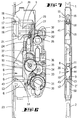
- the drive rod 1 is positively connected to a drive rod connecting slide 5, which is longitudinally displaceable in the castle.
- the positive connection 3 between the end region of the drive rod 1 and the end region of the drive rod connecting slide 5 has a projection 16 assigned to the connecting rod connecting slide 5.
- the projection 16 positively engages in an approximately keyhole-shaped recess 15 in the end region of the drive rod 1.
- the end region 17 of the drive rod 1 runs at an acute angle and, as shown in particular in FIG. 4, engages in a groove 18 in the latch head 19.
- the drive rod 1 continues below the keyhole-shaped recess 15, forming a recess 15 that is closed on all sides.
- the latch head 19 is detachably fastened to a latch tail 20 which is guided in a displaceable manner in the lock case.
- the attachment is carried out by screwing the latch head 19 to the gusset plate-like design Fastening leg 21 of the trap tail 20.
- the trap head 19 is coupled to the trap tail 20 via a positive connection.
- a bolt 25 is provided which interacts with a grub screw on the fastening leg 21 of the trap tail 20. It is provided, but not shown in the figures, that there may be several bores in the trap tail 20, into which the bolt 25 of the trap head 19 can be inserted and fastened with this or with other grub screws.
- the trap head 19 is connected to the fastening leg 21, for example, via a dovetail-shaped design.
- a grub screw can be provided for securing.
- the trap can be closed against spring loading both by means of a nut 26 and by means of a change lever 28.
- the change lever 28 has a lever arm 27 which lies in a pocket 29 of the trap tail 20.
- the change lever 28 is acted upon by a change plunger 24, which is guided so as to be displaceable in the longitudinal direction of the lock.
- the changing plunger 24 is displaced via a hook mechanism 30 when a toothed ring 31 is actuated.
- the nut 26 also has an arm 26 'which lies in an end pocket 32 of the trap tail 20.
- the pocket 29 and the pocket 32 lie on opposite side surfaces of the latch slide. They are offset from one another in the transverse direction.
- the drive rod connecting slide 5 and 6 are driven by a gear transmission.
- it is a reduction gear, consisting of the gear wheels 33, 34, 35, 36, which is driven by a ring gear 31.
- This has a radial recess for engaging a locking member of a locking cylinder.
- the last wheel 36 meshes with a rack 37, which is assigned to the connecting slide 6.
- the end region of the drive rod 2 facing the bolt 7 forms a two-fingered claw with fingers 12 and 13 angled against the faceplate 23 by means of a cutout 4 on the end face. While leaving a bridge-shaped web 2 ', a cutout 4 is followed by a longitudinal slot 50 for a locking cylinder fastening screw, not shown.
- the remaining web 2 ' provides sufficient stability and prevents the fingers 12, 13 from spreading apart.
- the thickness of the web 2' corresponds to approximately half the thickness of the drive rod 2, the outer surface of the web being flush with the wide surface of the drive rod 2 facing the faceplate 23 .
- the connecting rod connecting slide 6 is guided in the lock case on the cuff side. Its trajectory crosses the trajectory of the bolt 7. The bolt 7 thus lies on the connecting rod slide 6 in the closed position shown in FIG.
- the bolt 7 has a section which is formed by a recess 10 and has a thinner cross section.
- a central section 8 of the bolt 7 with a thicker cross section lies in this recess.
- the cutout of the exclusion contour of the central section 8 of the bar 7, which is thicker in cross section, is adapted.
- Its bolt tail 38 is coupled to the transmission in a manner not illustrated in any more detail.
- the bolt drive reference is made in particular to DE-40 14 043.
- the closing edges 41 of the latch 19 and the closing edge 39 of the bolt 7 are approximately aligned. While the latch 19 is guided on the lock floor, the bolt 7 slides on the section of the connecting rod connecting slide 6 which is thinner in cross-section and formed by the depression 10. The distance between the two alignment lines of the locking edges 41 and 39 therefore corresponds to the thickness of the remaining one formed by the depression 10 Section. The distance is about half a millimeter and thus corresponds to DIN 18 251.
- the cross-sectional shape of the bolt 7 is symmetrical in the faceplate plane. Towards the narrow side, the cross-sectionally thick central section 8 merges into a cross-sectionally smaller longitudinal section 9 or 11.
- the cross-section-thicker central section 8 forms closing edges on both sides, namely 39 and 40.
- the closing edges lie symmetrically to one another due to the bolt 7 arranged essentially centrally in the lock case, so that when the latch head 19 is turned, the lock can be used for both left-closing and right-closing doors.
- the closing edges 39 and 40 are each one of the Edges of the faceplate 23 equally spaced.
- the side surface of the bolt 7 assigned to the closing edge 40 is covered by the lock cover 44.
- the lock cover 44 can also have a small spacing from the outer edge of the faceplate 23 in this area.
- the two fingers 12 and 13 of the end region of the drive rod 2 overlap the longitudinal section 9, which is thinner in cross-section and is assigned to the side of the bolt 7 facing away from the latch.
- a rib 43 is formed which, in the closed closed position, supports the longitudinal section 9 of the bolt 7, which is thinner in cross section, which rib 43 also forms the form-fitting connection 12, 14 with the drive rod 2.
- a section 42 of the connecting rod connecting slide 6 with a thicker cross section comes under a partial area of the locking tail 38, which corresponds in its cross-sectional thickness approximately to the thinner longitudinal sections 9 and 11 of the locking bolt 7.
- the bolt tail 38 is relined by the drive rod region 42 even in the pre-closed bolt position.
- the drive rod area 42 is provided with a bevel in the transition area to the thinner section, so that the transition does not run in one step.
- the course of this slope is arranged to run obliquely to the direction of exclusion of the bolt because of the movement superimposition of the bolt exclusion and espagnolette connecting slide displacement and is adapted to the extent the exclusion contour of the bolt.
Landscapes
- Engineering & Computer Science (AREA)
- Mechanical Engineering (AREA)
- Lock And Its Accessories (AREA)
- Polysaccharides And Polysaccharide Derivatives (AREA)
- Saccharide Compounds (AREA)
- Mutual Connection Of Rods And Tubes (AREA)
- Clamps And Clips (AREA)
- Hooks, Suction Cups, And Attachment By Adhesive Means (AREA)
Applications Claiming Priority (2)
| Application Number | Priority Date | Filing Date | Title |
|---|---|---|---|
| DE4323725 | 1993-07-15 | ||
| DE4323725A DE4323725A1 (de) | 1993-07-15 | 1993-07-15 | Treibstangenschloß |
Publications (3)
| Publication Number | Publication Date |
|---|---|
| EP0634551A2 true EP0634551A2 (fr) | 1995-01-18 |
| EP0634551A3 EP0634551A3 (fr) | 1995-09-06 |
| EP0634551B1 EP0634551B1 (fr) | 1997-10-22 |
Family
ID=6492887
Family Applications (1)
| Application Number | Title | Priority Date | Filing Date |
|---|---|---|---|
| EP94106020A Expired - Lifetime EP0634551B1 (fr) | 1993-07-15 | 1994-04-19 | Crémone |
Country Status (3)
| Country | Link |
|---|---|
| EP (1) | EP0634551B1 (fr) |
| AT (1) | ATE159559T1 (fr) |
| DE (2) | DE4323725A1 (fr) |
Cited By (2)
| Publication number | Priority date | Publication date | Assignee | Title |
|---|---|---|---|---|
| AT14920U1 (de) * | 2015-02-19 | 2016-08-15 | Roto Frank Ag | Schloss |
| CN108561009A (zh) * | 2018-05-08 | 2018-09-21 | 陈坤 | 具有可拆卸过渡连接杆结构的锁体 |
Families Citing this family (1)
| Publication number | Priority date | Publication date | Assignee | Title |
|---|---|---|---|---|
| DE102019125148A1 (de) * | 2019-09-18 | 2021-03-18 | WILKA Schließtechnik GmbH | Nebenschloss für eine Mehrpunktverriegelung |
Family Cites Families (6)
| Publication number | Priority date | Publication date | Assignee | Title |
|---|---|---|---|---|
| DE2409480A1 (de) * | 1974-02-28 | 1975-09-04 | Frank Gmbh Wilh | Verschlussgetriebe, insbesondere fuer ein fenster, eine tuer o. dgl. |
| FR2432076A1 (fr) * | 1978-07-28 | 1980-02-22 | Picard | Ensemble de fermeture multipene |
| DE3836694C2 (de) * | 1988-10-28 | 1996-05-09 | Fliether Karl Gmbh & Co | Treibstangenschloß |
| SI8910445B (sl) * | 1989-03-01 | 1998-06-30 | KOVINOPLASTIKA LO� industrija kovinskih in | Naprava za blokiranje vratnih kril |
| DE4014043A1 (de) * | 1990-05-02 | 1991-11-07 | Fuhr Carl Gmbh & Co | Schliesszylinderbetaetigbares treibstangenschloss |
| DE4118427C2 (de) * | 1991-06-05 | 2000-10-26 | Fuhr Carl Gmbh & Co | Schloß, insbesondere Treibstangenschloß |
-
1993
- 1993-07-15 DE DE4323725A patent/DE4323725A1/de not_active Withdrawn
-
1994
- 1994-04-19 AT AT94106020T patent/ATE159559T1/de not_active IP Right Cessation
- 1994-04-19 EP EP94106020A patent/EP0634551B1/fr not_active Expired - Lifetime
- 1994-04-19 DE DE59404394T patent/DE59404394D1/de not_active Expired - Fee Related
Cited By (2)
| Publication number | Priority date | Publication date | Assignee | Title |
|---|---|---|---|---|
| AT14920U1 (de) * | 2015-02-19 | 2016-08-15 | Roto Frank Ag | Schloss |
| CN108561009A (zh) * | 2018-05-08 | 2018-09-21 | 陈坤 | 具有可拆卸过渡连接杆结构的锁体 |
Also Published As
| Publication number | Publication date |
|---|---|
| EP0634551A3 (fr) | 1995-09-06 |
| EP0634551B1 (fr) | 1997-10-22 |
| ATE159559T1 (de) | 1997-11-15 |
| DE4323725A1 (de) | 1995-01-19 |
| DE59404394D1 (de) | 1997-11-27 |
Similar Documents
| Publication | Publication Date | Title |
|---|---|---|
| DE3738300C2 (de) | Flügelrahmen für ein Fenster oder eine Tür, der aus Metall- oder Kunststoffprofilen zusammengesetzt ist | |
| DE2313690C2 (de) | Treibstangenbeschlag für Fenster, Türen od.dgl | |
| EP0634552B1 (fr) | Clef avec pêne rotatif, spécialement comme serrure supplémentaire à barres coulissantes | |
| EP2118414B1 (fr) | Armature de verrouillage et ensemble de pièces pour cette armature | |
| EP1049846A1 (fr) | Serrure pour porte en verre avec un element lateral fixe en verre | |
| EP1020597A1 (fr) | Serrure à crémone avec une serrure principal et une serrure complémentaire | |
| EP0634551B1 (fr) | Crémone | |
| EP0581338B1 (fr) | Serrure de barre coulissante manoeuvrable d'un barillet | |
| EP0995865A2 (fr) | Serrure, notamment crémone serrure | |
| EP1264954B1 (fr) | Système de verouillage | |
| DE3427713A1 (de) | Mehrtourig schliessendes treibstangenschloss | |
| EP1518978B1 (fr) | Boîtier récepteur pour gâche | |
| EP0592012A1 (fr) | Crémone | |
| EP1048803A2 (fr) | Dispositif de fermeture pour une serrure avec ouvertures d'insertion disposées de chaque côté | |
| DE9104766U1 (de) | Antipaniktürschloß | |
| DE20122859U1 (de) | Einsteckschloss mit Kunststoffriegel | |
| DE3215452A1 (de) | Eckumlenkung fuer treibstangenbeschlaege von fenstern, tueren od. dgl. | |
| EP0806534B1 (fr) | Crémone | |
| EP2532816B1 (fr) | Dispositif d'entraînement pour une armature de bielle | |
| EP1031692A1 (fr) | Couvercle pour fermetures dans fenêtres et/ou portes de bâtiments | |
| EP0947652A2 (fr) | Connection à chevauchement, notamment pour la têtière d'une espagnolette | |
| DE3807338A1 (de) | Schloss, insbesondere einsteckschloss | |
| EP1660745A1 (fr) | Dispositif de verrouillage de barre | |
| DE19854263C2 (de) | Überlappungsverbindung | |
| AT377568B (de) | Treibstangenbeschlaf fuer fenster, tueren od.dgl. |
Legal Events
| Date | Code | Title | Description |
|---|---|---|---|
| PUAI | Public reference made under article 153(3) epc to a published international application that has entered the european phase |
Free format text: ORIGINAL CODE: 0009012 |
|
| AK | Designated contracting states |
Kind code of ref document: A2 Designated state(s): AT DE FR |
|
| PUAL | Search report despatched |
Free format text: ORIGINAL CODE: 0009013 |
|
| AK | Designated contracting states |
Kind code of ref document: A3 Designated state(s): AT DE FR |
|
| 17P | Request for examination filed |
Effective date: 19951206 |
|
| 17Q | First examination report despatched |
Effective date: 19960913 |
|
| GRAG | Despatch of communication of intention to grant |
Free format text: ORIGINAL CODE: EPIDOS AGRA |
|
| GRAH | Despatch of communication of intention to grant a patent |
Free format text: ORIGINAL CODE: EPIDOS IGRA |
|
| GRAH | Despatch of communication of intention to grant a patent |
Free format text: ORIGINAL CODE: EPIDOS IGRA |
|
| GRAA | (expected) grant |
Free format text: ORIGINAL CODE: 0009210 |
|
| AK | Designated contracting states |
Kind code of ref document: B1 Designated state(s): AT DE FR |
|
| REF | Corresponds to: |
Ref document number: 159559 Country of ref document: AT Date of ref document: 19971115 Kind code of ref document: T |
|
| REF | Corresponds to: |
Ref document number: 59404394 Country of ref document: DE Date of ref document: 19971127 |
|
| ET | Fr: translation filed | ||
| PLBE | No opposition filed within time limit |
Free format text: ORIGINAL CODE: 0009261 |
|
| STAA | Information on the status of an ep patent application or granted ep patent |
Free format text: STATUS: NO OPPOSITION FILED WITHIN TIME LIMIT |
|
| 26N | No opposition filed | ||
| PGFP | Annual fee paid to national office [announced via postgrant information from national office to epo] |
Ref country code: FR Payment date: 20040402 Year of fee payment: 11 |
|
| PGFP | Annual fee paid to national office [announced via postgrant information from national office to epo] |
Ref country code: DE Payment date: 20040405 Year of fee payment: 11 |
|
| PGFP | Annual fee paid to national office [announced via postgrant information from national office to epo] |
Ref country code: AT Payment date: 20040426 Year of fee payment: 11 |
|
| PG25 | Lapsed in a contracting state [announced via postgrant information from national office to epo] |
Ref country code: AT Free format text: LAPSE BECAUSE OF NON-PAYMENT OF DUE FEES Effective date: 20050419 |
|
| PG25 | Lapsed in a contracting state [announced via postgrant information from national office to epo] |
Ref country code: DE Free format text: LAPSE BECAUSE OF NON-PAYMENT OF DUE FEES Effective date: 20051101 |
|
| PG25 | Lapsed in a contracting state [announced via postgrant information from national office to epo] |
Ref country code: FR Free format text: LAPSE BECAUSE OF NON-PAYMENT OF DUE FEES Effective date: 20051230 |
|
| REG | Reference to a national code |
Ref country code: FR Ref legal event code: ST Effective date: 20051230 |