EP0634575A2 - Vorrichtung zur Verteilung einer gasförmigen Komponente in Ionisationskammern für Raumfahrtantrieb - Google Patents
Vorrichtung zur Verteilung einer gasförmigen Komponente in Ionisationskammern für Raumfahrtantrieb Download PDFInfo
- Publication number
- EP0634575A2 EP0634575A2 EP94830345A EP94830345A EP0634575A2 EP 0634575 A2 EP0634575 A2 EP 0634575A2 EP 94830345 A EP94830345 A EP 94830345A EP 94830345 A EP94830345 A EP 94830345A EP 0634575 A2 EP0634575 A2 EP 0634575A2
- Authority
- EP
- European Patent Office
- Prior art keywords
- component
- wall
- gas
- holes
- passage
- Prior art date
- Legal status (The legal status is an assumption and is not a legal conclusion. Google has not performed a legal analysis and makes no representation as to the accuracy of the status listed.)
- Granted
Links
Images

Classifications
-
- H—ELECTRICITY
- H01—ELECTRIC ELEMENTS
- H01J—ELECTRIC DISCHARGE TUBES OR DISCHARGE LAMPS
- H01J37/00—Discharge tubes with provision for introducing objects or material to be exposed to the discharge, e.g. for the purpose of examination or processing thereof
- H01J37/32—Gas-filled discharge tubes
- H01J37/32431—Constructional details of the reactor
- H01J37/3244—Gas supply means
-
- B—PERFORMING OPERATIONS; TRANSPORTING
- B64—AIRCRAFT; AVIATION; COSMONAUTICS
- B64G—COSMONAUTICS; VEHICLES OR EQUIPMENT THEREFOR
- B64G1/00—Cosmonautic vehicles
- B64G1/22—Parts of, or equipment specially adapted for fitting in or to, cosmonautic vehicles
- B64G1/40—Arrangements or adaptations of propulsion systems
- B64G1/402—Propellant tanks; Feeding propellants
-
- B—PERFORMING OPERATIONS; TRANSPORTING
- B64—AIRCRAFT; AVIATION; COSMONAUTICS
- B64G—COSMONAUTICS; VEHICLES OR EQUIPMENT THEREFOR
- B64G1/00—Cosmonautic vehicles
- B64G1/22—Parts of, or equipment specially adapted for fitting in or to, cosmonautic vehicles
- B64G1/40—Arrangements or adaptations of propulsion systems
- B64G1/411—Electric propulsion
- B64G1/413—Ion or plasma engines
-
- F—MECHANICAL ENGINEERING; LIGHTING; HEATING; WEAPONS; BLASTING
- F03—MACHINES OR ENGINES FOR LIQUIDS; WIND, SPRING, OR WEIGHT MOTORS; PRODUCING MECHANICAL POWER OR A REACTIVE PROPULSIVE THRUST, NOT OTHERWISE PROVIDED FOR
- F03H—PRODUCING A REACTIVE PROPULSIVE THRUST, NOT OTHERWISE PROVIDED FOR
- F03H1/00—Using plasma to produce a reactive propulsive thrust
-
- H—ELECTRICITY
- H01—ELECTRIC ELEMENTS
- H01J—ELECTRIC DISCHARGE TUBES OR DISCHARGE LAMPS
- H01J27/00—Ion beam tubes
- H01J27/02—Ion sources; Ion guns
- H01J27/022—Details
Definitions
- the invention relates to a new system for the distribution of gas within an ionization chamber.
- Devices which use ionization chambers in which, by the application of a suitable electrical field and possibly a magnetic field, the ionization of a gas is achieved are known and used in various technological applications; for example, in surface treatments there are various devices which, by the ionization of one or more gases, can be used for processes such as the deposition of thin films on targets placed in front of the device ("deposition"), or the selective erosion of certain layers of the target (“etching”), and other purposes.
- the device is normally known as an electrical thruster, and in summary consists of a chamber made of any of various materials, generally cylindrical in shape, into which the propellant (gas) is introduced through a suitable gas distributor, and in which the propellant is ionized; suitable electrically conditioned means designed to create a discharge in the gas; and further means capable of accelerating the ionized gas towards the outside.
- This device is used to generate the plasma which is accelerated towards the outside and is thus capable of producing a thrust.
- the invention relates to an innovative technological solution for the distribution of the gas within ionization devices, such as those illustrated above as non-restrictive examples.
- the propellant enters the discharge chambers of user devices through a flow line which carries the gas from a reservoir or container (for example, a cylinder) of the gas, which is generally pressurized, to the ionization chamber, various devices capable of controlling the flow, such as pressure limiters, line opening and closing valves, flow controllers, and others, being normally disposed on the said line.
- the gas is then introduced into the ionization chamber through a suitable distributor whose shape and materials may vary.
- These distributors may be single nozzles with a single hole, as indicated (Fig. 1) by 1, from which the gas emerges inside the discharge chamber 3, or multiple nozzles 5, with a plurality of outlet holes 5A (Fig. 2) opening into the chamber 7, or of the type indicated in Fig.
- Each ionization chamber comprises means (not illustrated) for generating electrical or magnetic fields for ionization, to split the gas molecules into ions and electrons, and means (not illustrated) for accelerating the ions, for example in a vacuum in the case of electrical thrusters used in the space field.
- the present distributor device comprising at least one nozzle with a calibrated hole for the discharge of the gas into the ionization chamber, is one wherein the calibrated hole is formed in a component made of hard material which is inserted in the wall of the distributor, at the position of a passage formed in the wall.
- the said component may be fixed to the wall with an adjustable orientation.
- the said component and the wall may have, for mutual contact, complementary surfaces of revolution, which permit variations of orientation of the component; these surfaces may advantageously be portions of spherical surfaces.
- the pierced component may be a ruby or other equivalent hard material.
- each nozzle may be formed from a pierced component made of hard material.
- the said component may be applied to the outside of the wall provided with the passage, or to the inside.
- the invention therefore relates to a versatile device which can be used to control the characteristics of the outflow of the gas into the discharge chamber in such a way as to make it, if required, as turbulent as possible, and which may be easily modified so that it can be used in different conditions of gas flow.
- the device comprises a support 11 of suitable shape (in the shape of a ring in the drawing), which has one or more connectors 13 for connection to the gas flow line, which carries the gas from the storage reservoir to the distribution device.
- the support 11 has a plurality of calibrated holes disposed on one or more faces. These holes - of suitable dimensions - are made in small components 15 made of hard material, for example rubies such as those used in watchmaking; these components 15 are of variable shape and are set with a seal on the principal support 11.
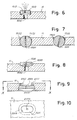
- Figs. 6-8 show possible but not restrictive examples of pierced components 15.
- components 1510 in tablet form are provided, with concavities if required to decrease their thickness, and have calibrated holes 1512 and are partially set in the wall of the distributor 11 at the position of a passage 1514; the tablet 1510 is fixed in the wall with an inclination if necessary, stabilized by the adhesive used for fixing.
- the fixing may also be achieved by force fitting.
- a socket 1520 passing through the wall is provided, with a portion of spherical surface for contact with a component 1522 with a spherical surface pierced by a calibrated through hole 1524; the component 1522 may be fixed in the socket 1520 with a desired inclination within a limiting cone.
- Fig. 8 shows a tablet component 1530 with a through hole 1532; complementary surfaces in the form of segments of a sphere are formed by the wall 11, around a passage 1534, and by the tablet component, to permit fixing with a desired angular orientation of the hole 1532.
- the components 1510, 1522, 1530 or equivalent may consist of small rubies, with the thin holes for the passage of the gas.
- the embodiments described above require the application of the pierced components 1510, 1522, 1530 or other on the outside of the wall 11 of the support forming the main duct for the supply of the nozzle or nozzles.
- the application may be on the inside, with greater protection (by the effect of locking by shape) from the stress of differential pressure between the inside and the outside, in other words the chamber 3.
- fitting can be from the outside but still with locking by shape.
- a component 2001 with the calibrated hole 2003 has an oval shape or in any case one of its dimensions is smaller than the dimension perpendicular to it, and the socket 2005 passing through the wall 11 also has corresponding dimensions; the joining surfaces are tapered towards the outside, and may also have suitable curved profiles, to permit the inclined orientation of the component 2001 and the hole 2003.
- the component 2003, suitably supported, may be introduced lengthways into the passage 2005 and then orientated to be positioned and if necessary glued in the socket formed by the passage 2005, by manipulation from the outside.
- the said small components are disposed, during setting, in such a way that the calibrated holes are disposed with the desired inclinations which may be different from each other, to increase the efficiency of the device for the purposes of obtaining turbulence in the discharge within the ionization chamber.
- the calibrated holes may be different if required.
- inserted components such as 15, 1510, 1522, and 1530 is advantageous when it is necessary to create devices with a plurality of outlet holes which may sometimes number up to 90 or 100.
- the difficulty in making these holes is due to the fact that, during piercing, if even a single hole is faulty the piece has to be completely remade. This risk can be avoided by using calibrated holes already made in hard materials which are subsequently set in the support.
- the gas outflow parameters (such as the velocity and density of the neutral particles) in proximity to the gas distributor, and in some cases throughout the whole ionization chamber, these parameters being theoretically dependent not only on the shape and disposition of the support in the chamber as a whole and the geometry of the chamber, but also on the type and number of holes present in the gas dispenser element, as is familiar to those skilled in the art and as is well known from the application of the laws of gas dynamics.
- the number, diameter and inclination with respect to each other of the calibrated holes from which the gas flows out is of fundamental importance for the determination of the parameters of the gas jet in the discharge chamber.
- the distribution of the neutral particles and their velocity in the ionization chamber is important for the performance of the device of which the chamber forms part.
- the saving of gas is one of the parameters which determines the quality of the thruster; and this saving - for a fixed obtainable thrust and electrical power consumption - may be obtained if there is a high gas ionization efficiency in the discharge chamber.
- One possible way of obtaining an increase in this efficiency is to attempt to maintain the neutral particles for the longest possible time in the discharge chamber in order to increase the probability of their being ionized and in order to extract only ions responsible for the thrust as a result of the acceleration acquired from the applied electrical fields.
- the possibility of being able to control - by means of a suitable disposition of the gas distributor (number of holes, their diameter and positioning and orientation of the holes on the support) - the outflow parameters of the gas therefore has advantageous effects in certain applications such as electrical propulsion.
- the holes interchangeable simply by exchanging the components made of hard material (for example rubies), which are simply set in the principal element, for others with holes of different diameters.
- the interchangeability of the holes also enables the device to be used in different flow conditions or enables the same device to be used in ionization chambers which are made to operate in completely different gas flow conditions.
- the use of a gas distributor in an ionization chamber according to the invention may have positive effects both in terms of the performance of the device and in terms of the cost of the device.
- the application of the device according to the invention to plasma motors of the SPT (Stationary Plasma Thruster) type is particularly advantageous.
Landscapes
- Engineering & Computer Science (AREA)
- Chemical & Material Sciences (AREA)
- Combustion & Propulsion (AREA)
- Plasma & Fusion (AREA)
- Aviation & Aerospace Engineering (AREA)
- Physics & Mathematics (AREA)
- Remote Sensing (AREA)
- Mechanical Engineering (AREA)
- General Engineering & Computer Science (AREA)
- Analytical Chemistry (AREA)
- Other Investigation Or Analysis Of Materials By Electrical Means (AREA)
- Plasma Technology (AREA)
- Blow-Moulding Or Thermoforming Of Plastics Or The Like (AREA)
- Electron Sources, Ion Sources (AREA)
- Physical Or Chemical Processes And Apparatus (AREA)
Applications Claiming Priority (2)
| Application Number | Priority Date | Filing Date | Title |
|---|---|---|---|
| ITFI930129 | 1993-07-13 | ||
| ITFI930129A IT1263092B (it) | 1993-07-13 | 1993-07-13 | Dispositivo distributore di un componente gassoso in camere di ionizzazione, per propulsori spaziali ed altro |
Publications (3)
| Publication Number | Publication Date |
|---|---|
| EP0634575A2 true EP0634575A2 (de) | 1995-01-18 |
| EP0634575A3 EP0634575A3 (en) | 1995-02-15 |
| EP0634575B1 EP0634575B1 (de) | 1998-05-06 |
Family
ID=11350528
Family Applications (1)
| Application Number | Title | Priority Date | Filing Date |
|---|---|---|---|
| EP94830345A Expired - Lifetime EP0634575B1 (de) | 1993-07-13 | 1994-07-11 | Vorrichtung zur Verteilung einer gasförmigen Komponente in Ionisationskammern für Raumfahrtantrieb |
Country Status (5)
| Country | Link |
|---|---|
| EP (1) | EP0634575B1 (de) |
| JP (1) | JPH0754764A (de) |
| AT (1) | ATE165901T1 (de) |
| DE (1) | DE69410026D1 (de) |
| IT (1) | IT1263092B (de) |
Cited By (2)
| Publication number | Priority date | Publication date | Assignee | Title |
|---|---|---|---|---|
| EP0768702A1 (de) * | 1995-10-16 | 1997-04-16 | Applied Materials, Inc. | Schlitz-Gasinjektionsdüse für einen Plasmabearbeitungsreaktion |
| CN115946876A (zh) * | 2022-04-13 | 2023-04-11 | 国科大杭州高等研究院 | 一种微牛级宝石基双气容变推力闭环冷气推力器的运行方法 |
Families Citing this family (2)
| Publication number | Priority date | Publication date | Assignee | Title |
|---|---|---|---|---|
| RU2147387C1 (ru) * | 1998-09-29 | 2000-04-10 | Институт проблем технологии микроэлектроники и особочистых материалов РАН | Плазменный ионный источник |
| US9823177B2 (en) | 2014-02-27 | 2017-11-21 | Alliance For Sustainable Energy, Llc | Calibrated permeation standards |
Family Cites Families (1)
| Publication number | Priority date | Publication date | Assignee | Title |
|---|---|---|---|---|
| DE4122755A1 (de) * | 1991-07-10 | 1993-01-21 | Erno Raumfahrttechnik Gmbh | Triebwerk fuer raumflugkoerper |
-
1993
- 1993-07-13 IT ITFI930129A patent/IT1263092B/it active IP Right Grant
-
1994
- 1994-07-11 AT AT94830345T patent/ATE165901T1/de not_active IP Right Cessation
- 1994-07-11 DE DE69410026T patent/DE69410026D1/de not_active Expired - Lifetime
- 1994-07-11 EP EP94830345A patent/EP0634575B1/de not_active Expired - Lifetime
- 1994-07-13 JP JP6161538A patent/JPH0754764A/ja active Pending
Cited By (3)
| Publication number | Priority date | Publication date | Assignee | Title |
|---|---|---|---|---|
| US5746875A (en) * | 1994-09-16 | 1998-05-05 | Applied Materials, Inc. | Gas injection slit nozzle for a plasma process reactor |
| EP0768702A1 (de) * | 1995-10-16 | 1997-04-16 | Applied Materials, Inc. | Schlitz-Gasinjektionsdüse für einen Plasmabearbeitungsreaktion |
| CN115946876A (zh) * | 2022-04-13 | 2023-04-11 | 国科大杭州高等研究院 | 一种微牛级宝石基双气容变推力闭环冷气推力器的运行方法 |
Also Published As
| Publication number | Publication date |
|---|---|
| JPH0754764A (ja) | 1995-02-28 |
| IT1263092B (it) | 1996-07-24 |
| ITFI930129A0 (it) | 1993-07-13 |
| ATE165901T1 (de) | 1998-05-15 |
| DE69410026D1 (de) | 1998-06-10 |
| ITFI930129A1 (it) | 1995-01-13 |
| EP0634575A3 (en) | 1995-02-15 |
| EP0634575B1 (de) | 1998-05-06 |
Similar Documents
| Publication | Publication Date | Title |
|---|---|---|
| JP2651980B2 (ja) | クローズド電子ドリフトを備えたプラズマ加速器 | |
| US3735591A (en) | Magneto-plasma-dynamic arc thruster | |
| KR101380793B1 (ko) | 하이브리드 플라즈마-콜드 스프레이 방법 및 장치 | |
| US9897079B2 (en) | External discharge hall thruster | |
| US6449941B1 (en) | Hall effect electric propulsion system | |
| US8448419B2 (en) | Electrospray source | |
| RU2620880C2 (ru) | Двигатель на эффекте холла | |
| US20230033091A1 (en) | Plasma processing apparatus including gas distribution plate | |
| EP4114741B1 (de) | Antriebssystem für raumfahrzeuge | |
| JPH10259782A (ja) | 寿命の長いイオン−光学システムを有するイオンスラスタ | |
| CN112639287B (zh) | 用于航天器的推力矢量推进的离子推力器 | |
| US10436183B2 (en) | Plasma accelerating apparatus and plasma accelerating method | |
| US20180051679A1 (en) | Thruster | |
| EP0634575A2 (de) | Vorrichtung zur Verteilung einer gasförmigen Komponente in Ionisationskammern für Raumfahrtantrieb | |
| US20070033920A1 (en) | Method of ionizing a liquid and an electrostatic colloid thruster implementing such a method | |
| CN115681055A (zh) | 紧凑型气体分配器及霍尔推力器 | |
| US3627204A (en) | Spray nozzle for plasma guns | |
| EP3242534A1 (de) | Vorrichtung zur erzeugung eines plasma-jets, insbesonders für den raumantrieb | |
| US20240401576A1 (en) | Hall-effect thruster system with applied counter-torque | |
| US3645475A (en) | Fluid amplifier with direct-coupled gyrocontrol | |
| EP1082541A1 (de) | Gleichmässige gasverteilung in ionenbeschleunigern mit geschlossener ionenbahn | |
| US3570513A (en) | Electrohydrodynamic control valve | |
| WO1998047049A1 (en) | Apertured nonplanar electrodes and forming methods | |
| Schrade et al. | Cathode phenomena in plasma thrusters | |
| JP4571003B2 (ja) | クラスターイオンビーム装置 |
Legal Events
| Date | Code | Title | Description |
|---|---|---|---|
| PUAI | Public reference made under article 153(3) epc to a published international application that has entered the european phase |
Free format text: ORIGINAL CODE: 0009012 |
|
| PUAL | Search report despatched |
Free format text: ORIGINAL CODE: 0009013 |
|
| AK | Designated contracting states |
Kind code of ref document: A2 Designated state(s): AT BE CH DE DK ES FR GB GR IE LI LU MC NL PT SE |
|
| AK | Designated contracting states |
Kind code of ref document: A3 Designated state(s): AT BE CH DE DK ES FR GB GR IE LI LU MC NL PT SE |
|
| 17P | Request for examination filed |
Effective date: 19950805 |
|
| 17Q | First examination report despatched |
Effective date: 19960906 |
|
| GRAG | Despatch of communication of intention to grant |
Free format text: ORIGINAL CODE: EPIDOS AGRA |
|
| RAP1 | Party data changed (applicant data changed or rights of an application transferred) |
Owner name: LABEN S.P.A. |
|
| GRAG | Despatch of communication of intention to grant |
Free format text: ORIGINAL CODE: EPIDOS AGRA |
|
| GRAH | Despatch of communication of intention to grant a patent |
Free format text: ORIGINAL CODE: EPIDOS IGRA |
|
| GRAH | Despatch of communication of intention to grant a patent |
Free format text: ORIGINAL CODE: EPIDOS IGRA |
|
| GRAA | (expected) grant |
Free format text: ORIGINAL CODE: 0009210 |
|
| AK | Designated contracting states |
Kind code of ref document: B1 Designated state(s): AT BE CH DE DK ES FR GB GR IE LI LU MC NL PT SE |
|
| PG25 | Lapsed in a contracting state [announced via postgrant information from national office to epo] |
Ref country code: NL Free format text: LAPSE BECAUSE OF FAILURE TO SUBMIT A TRANSLATION OF THE DESCRIPTION OR TO PAY THE FEE WITHIN THE PRESCRIBED TIME-LIMIT Effective date: 19980506 Ref country code: LI Free format text: LAPSE BECAUSE OF FAILURE TO SUBMIT A TRANSLATION OF THE DESCRIPTION OR TO PAY THE FEE WITHIN THE PRESCRIBED TIME-LIMIT Effective date: 19980506 Ref country code: GR Free format text: LAPSE BECAUSE OF FAILURE TO SUBMIT A TRANSLATION OF THE DESCRIPTION OR TO PAY THE FEE WITHIN THE PRESCRIBED TIME-LIMIT Effective date: 19980506 Ref country code: ES Free format text: THE PATENT HAS BEEN ANNULLED BY A DECISION OF A NATIONAL AUTHORITY Effective date: 19980506 Ref country code: CH Free format text: LAPSE BECAUSE OF FAILURE TO SUBMIT A TRANSLATION OF THE DESCRIPTION OR TO PAY THE FEE WITHIN THE PRESCRIBED TIME-LIMIT Effective date: 19980506 Ref country code: BE Free format text: LAPSE BECAUSE OF FAILURE TO SUBMIT A TRANSLATION OF THE DESCRIPTION OR TO PAY THE FEE WITHIN THE PRESCRIBED TIME-LIMIT Effective date: 19980506 Ref country code: AT Free format text: LAPSE BECAUSE OF FAILURE TO SUBMIT A TRANSLATION OF THE DESCRIPTION OR TO PAY THE FEE WITHIN THE PRESCRIBED TIME-LIMIT Effective date: 19980506 |
|
| REF | Corresponds to: |
Ref document number: 165901 Country of ref document: AT Date of ref document: 19980515 Kind code of ref document: T |
|
| REG | Reference to a national code |
Ref country code: CH Ref legal event code: EP |
|
| REF | Corresponds to: |
Ref document number: 69410026 Country of ref document: DE Date of ref document: 19980610 |
|
| PG25 | Lapsed in a contracting state [announced via postgrant information from national office to epo] |
Ref country code: LU Free format text: LAPSE BECAUSE OF NON-PAYMENT OF DUE FEES Effective date: 19980711 Ref country code: IE Free format text: LAPSE BECAUSE OF NON-PAYMENT OF DUE FEES Effective date: 19980711 |
|
| PG25 | Lapsed in a contracting state [announced via postgrant information from national office to epo] |
Ref country code: SE Free format text: LAPSE BECAUSE OF FAILURE TO SUBMIT A TRANSLATION OF THE DESCRIPTION OR TO PAY THE FEE WITHIN THE PRESCRIBED TIME-LIMIT Effective date: 19980806 Ref country code: PT Free format text: LAPSE BECAUSE OF FAILURE TO SUBMIT A TRANSLATION OF THE DESCRIPTION OR TO PAY THE FEE WITHIN THE PRESCRIBED TIME-LIMIT Effective date: 19980806 Ref country code: GB Free format text: LAPSE BECAUSE OF NON-PAYMENT OF DUE FEES Effective date: 19980806 Ref country code: DK Free format text: LAPSE BECAUSE OF FAILURE TO SUBMIT A TRANSLATION OF THE DESCRIPTION OR TO PAY THE FEE WITHIN THE PRESCRIBED TIME-LIMIT Effective date: 19980806 |
|
| PG25 | Lapsed in a contracting state [announced via postgrant information from national office to epo] |
Ref country code: DE Free format text: LAPSE BECAUSE OF FAILURE TO SUBMIT A TRANSLATION OF THE DESCRIPTION OR TO PAY THE FEE WITHIN THE PRESCRIBED TIME-LIMIT Effective date: 19980807 |
|
| REG | Reference to a national code |
Ref country code: IE Ref legal event code: FG4D Free format text: 80174 |
|
| ET | Fr: translation filed | ||
| NLV1 | Nl: lapsed or annulled due to failure to fulfill the requirements of art. 29p and 29m of the patents act | ||
| REG | Reference to a national code |
Ref country code: CH Ref legal event code: PL |
|
| PG25 | Lapsed in a contracting state [announced via postgrant information from national office to epo] |
Ref country code: MC Free format text: LAPSE BECAUSE OF NON-PAYMENT OF DUE FEES Effective date: 19990131 |
|
| PLBE | No opposition filed within time limit |
Free format text: ORIGINAL CODE: 0009261 |
|
| STAA | Information on the status of an ep patent application or granted ep patent |
Free format text: STATUS: NO OPPOSITION FILED WITHIN TIME LIMIT |
|
| GBPC | Gb: european patent ceased through non-payment of renewal fee |
Effective date: 19980806 |
|
| 26N | No opposition filed | ||
| REG | Reference to a national code |
Ref country code: FR Ref legal event code: CD Ref country code: FR Ref legal event code: CA |
|
| REG | Reference to a national code |
Ref country code: FR Ref legal event code: TP |
|
| PGFP | Annual fee paid to national office [announced via postgrant information from national office to epo] |
Ref country code: FR Payment date: 20070712 Year of fee payment: 14 |
|
| REG | Reference to a national code |
Ref country code: FR Ref legal event code: ST Effective date: 20090331 |
|
| PG25 | Lapsed in a contracting state [announced via postgrant information from national office to epo] |
Ref country code: FR Free format text: LAPSE BECAUSE OF NON-PAYMENT OF DUE FEES Effective date: 20080731 |