EP0634600A1 - Connecteur et raccord pour tuyaux ondulés - Google Patents
Connecteur et raccord pour tuyaux ondulés Download PDFInfo
- Publication number
- EP0634600A1 EP0634600A1 EP93111354A EP93111354A EP0634600A1 EP 0634600 A1 EP0634600 A1 EP 0634600A1 EP 93111354 A EP93111354 A EP 93111354A EP 93111354 A EP93111354 A EP 93111354A EP 0634600 A1 EP0634600 A1 EP 0634600A1
- Authority
- EP
- European Patent Office
- Prior art keywords
- sleeve
- housing
- connecting piece
- jacket
- positioning element
- Prior art date
- Legal status (The legal status is an assumption and is not a legal conclusion. Google has not performed a legal analysis and makes no representation as to the accuracy of the status listed.)
- Granted
Links
- 238000009434 installation Methods 0.000 claims description 12
- 238000003780 insertion Methods 0.000 claims description 10
- 230000037431 insertion Effects 0.000 claims description 10
- 238000007789 sealing Methods 0.000 claims description 5
- 230000008878 coupling Effects 0.000 description 7
- 238000010168 coupling process Methods 0.000 description 7
- 238000005859 coupling reaction Methods 0.000 description 7
- 239000004033 plastic Substances 0.000 description 3
- 239000000243 solution Substances 0.000 description 3
- 238000013461 design Methods 0.000 description 2
- 238000006073 displacement reaction Methods 0.000 description 2
- 239000000463 material Substances 0.000 description 2
- 241000209035 Ilex Species 0.000 description 1
- 239000004952 Polyamide Substances 0.000 description 1
- 230000006978 adaptation Effects 0.000 description 1
- 230000000903 blocking effect Effects 0.000 description 1
- 230000001419 dependent effect Effects 0.000 description 1
- 238000011161 development Methods 0.000 description 1
- 230000018109 developmental process Effects 0.000 description 1
- 238000001746 injection moulding Methods 0.000 description 1
- 238000000034 method Methods 0.000 description 1
- 238000012986 modification Methods 0.000 description 1
- 230000004048 modification Effects 0.000 description 1
- 229920002647 polyamide Polymers 0.000 description 1
- 230000001681 protective effect Effects 0.000 description 1
Images
Classifications
-
- F—MECHANICAL ENGINEERING; LIGHTING; HEATING; WEAPONS; BLASTING
- F16—ENGINEERING ELEMENTS AND UNITS; GENERAL MEASURES FOR PRODUCING AND MAINTAINING EFFECTIVE FUNCTIONING OF MACHINES OR INSTALLATIONS; THERMAL INSULATION IN GENERAL
- F16L—PIPES; JOINTS OR FITTINGS FOR PIPES; SUPPORTS FOR PIPES, CABLES OR PROTECTIVE TUBING; MEANS FOR THERMAL INSULATION IN GENERAL
- F16L25/00—Construction or details of pipe joints not provided for in, or of interest apart from, groups F16L13/00 - F16L23/00
- F16L25/0036—Joints for corrugated pipes
- F16L25/0045—Joints for corrugated pipes of the quick-acting type
-
- F—MECHANICAL ENGINEERING; LIGHTING; HEATING; WEAPONS; BLASTING
- F16—ENGINEERING ELEMENTS AND UNITS; GENERAL MEASURES FOR PRODUCING AND MAINTAINING EFFECTIVE FUNCTIONING OF MACHINES OR INSTALLATIONS; THERMAL INSULATION IN GENERAL
- F16L—PIPES; JOINTS OR FITTINGS FOR PIPES; SUPPORTS FOR PIPES, CABLES OR PROTECTIVE TUBING; MEANS FOR THERMAL INSULATION IN GENERAL
- F16L37/00—Couplings of the quick-acting type
- F16L37/08—Couplings of the quick-acting type in which the connection between abutting or axially overlapping ends is maintained by locking members
- F16L37/084—Couplings of the quick-acting type in which the connection between abutting or axially overlapping ends is maintained by locking members combined with automatic locking
- F16L37/098—Couplings of the quick-acting type in which the connection between abutting or axially overlapping ends is maintained by locking members combined with automatic locking by means of flexible hooks
-
- H—ELECTRICITY
- H02—GENERATION; CONVERSION OR DISTRIBUTION OF ELECTRIC POWER
- H02G—INSTALLATION OF ELECTRIC CABLES OR LINES, OR OF COMBINED OPTICAL AND ELECTRIC CABLES OR LINES
- H02G3/00—Installations of electric cables or lines or protective tubing therefor in or on buildings, equivalent structures or vehicles
- H02G3/02—Details
- H02G3/06—Joints for connecting lengths of protective tubing or channels, to each other or to casings, e.g. to distribution boxes; Ensuring electrical continuity in the joint
- H02G3/0616—Joints for connecting tubing to casing
-
- Y—GENERAL TAGGING OF NEW TECHNOLOGICAL DEVELOPMENTS; GENERAL TAGGING OF CROSS-SECTIONAL TECHNOLOGIES SPANNING OVER SEVERAL SECTIONS OF THE IPC; TECHNICAL SUBJECTS COVERED BY FORMER USPC CROSS-REFERENCE ART COLLECTIONS [XRACs] AND DIGESTS
- Y10—TECHNICAL SUBJECTS COVERED BY FORMER USPC
- Y10S—TECHNICAL SUBJECTS COVERED BY FORMER USPC CROSS-REFERENCE ART COLLECTIONS [XRACs] AND DIGESTS
- Y10S285/00—Pipe joints or couplings
- Y10S285/903—Corrugated
Definitions
- the invention relates to a connecting and connecting piece for corrugated tubes with at least one core cavity enclosed by a housing with an insertion opening for receiving one end of the tube and an opposite passage, and at least one resilient element, which with cams for engagement in the recesses on the jacket of the Corrugated tube is provided and an outer ring for locking the resilient element in a locked position.
- Corrugated pipes are used in a wide range, in particular also as protective hoses for cables, for example control cables.
- Various embodiments of connecting and connecting pieces are also known, by means of which corrugated pipes can be connected to one another or connected to housings.
- the connecting or connecting piece consists of a tubular housing with a core cavity into which the end of a corrugated tube is inserted. Incisions are made at the front ends of the housing, through which tab-shaped elements are cut out of the casing of the housing. These elements have cams on their inside which engage in the recesses on the jacket of the corrugated tube.
- the tabs can be widened outwards and the tube can thereby be inserted.
- At least one coupling ring on the housing which is slidable on the housing jacket.
- the union or outer ring is in a position behind the locking cam, so that the housing tabs can spring outwards due to their own elasticity or be displaced by the inserted pipe.
- the collar ring is pushed over the locking cam and the housing tabs are pressed onto the jacket of the corrugated pipe.
- the inside diameter of the collar ring is dimensioned so that a firm, form-fitting connection is created.
- the coupling ring is in this connection position between the locking cam and the end stop, which are designed so that the ring is held in this position under normal operating conditions.
- the strength of the connecting and connecting piece described here is considerably reduced by the housing tabs cut into the housing. In the event of heavy loads, breaks can occur on the end parts of the tabs or on other parts of the housing. As a result, the security of the connection is not always guaranteed.
- connection between the pipe and the connecting piece is made incorrectly, there is also the danger that the coupling ring is pushed over the tabs before the pipe end has been pushed sufficiently into the connecting piece. There is therefore a risk that the pipe end will not be held correctly and can be torn out of the connection. Since the coupling ring, which forms the locking element for the tabs, lies on the outer jacket of the connecting or connecting piece, there is also the risk that it will be inadvertently pushed out of the locking position into the starting position. In this case the connection between the pipe end and the connector would be released, which is undesirable. If the ring and the locking cam are so strong that an unintentional loosening is practically avoided, the locking connection can hardly be loosened without destroying the connecting or connecting piece. The handling of such connections during disassembly or modification work becomes difficult and complex.
- the arrangement according to the invention of a sleeve between the corrugated tube and the housing of the connecting or connecting piece enables the components to be optimally adapted to the required conditions.
- the housing can be dimensioned and designed in accordance with the strength requirements for the connection, and there are no elements on the outer surface of the housing which could be disturbed or actuated by adjacent connecting pieces or machine parts.
- the sleeve which is independent of the housing and carries the resilient elements, can also be optimally adapted to the requirements of the connection between the pipe end and the connector. Since the components are usually made of plastic, different materials can be used for the housing and the sleeve, which are optimally matched to the requirements.
- the resilient jacket elements on the sleeve can be designed such that they spring out so far outwards in the assembly position, ie before the tube end is inserted are that the free inside diameter of the sleeve is larger than the outside diameter of the pipe end. This ensures that the pipe end is inserted up to the collar at the inner end of the sleeve before the sleeve is displaced and thus the clamping process between the sleeve and the pipe end is initiated. This ensures that the pipe end is pushed sufficiently far into the sleeve and that the desired strength of the connection is achieved after it has been fixed in the housing.
- the sleeve Since the tube end rests on the collar of the inner end of the sleeve, the sleeve is pushed into the housing by further pushing the tube end into the core cavity of the housing and the resilient jacket elements are thereby pressed through the outer ring of the housing against the jacket of the corrugated tube.
- the installation position ie when the pipe end and the sleeve are fully inserted into the housing, the locking element on the outer jacket of the sleeve interacts with a counterpart on the housing and holds the sleeve in this position.
- the corrugated pipe end is thereby fixed in the housing of the connecting or connecting piece, and the desired connection is ensured.
- the counterpart in the housing to the locking element can be formed by a recess, an opening or another suitable configuration known per se.
- the sleeve In the assembly position, ie before the tube and connector are pushed together, the sleeve is held in the housing by a positioning element, which in this position also engages in the counterpart on the housing.
- a positioning element which in this position also engages in the counterpart on the housing.
- the area of the housing between the front surface and the Counterpart in the housing is designed so that this area can be expanded elastically and both the positioning element and the locking element on the sleeve can be pushed from the outside inwards.
- a recess is arranged in this area, which enables the insertion of a tool in the axial direction of the connecting piece between the sleeve and the housing.
- the design of the sleeve which is independent of the housing, allows easy adaptation to different external shapes of corrugated pipes, in that only the cams of the sleeve need to be adapted to the external shape of the pipe, but otherwise the same housing can be used.
- Another advantage of the embodiment according to the invention is that a sealing cap can be arranged in a simple manner at the inner end of the sleeve, which ensures complete tightness between the housing and the pipe end.
- the design of this sealing cap can also be designed differently without changes to the housing. Installation is easy because the seal is brought together with the sleeve and pushed into the housing together with it.
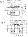
- Fig. 1 shows a connector 1, which is intended for the connection of a corrugated tube 2 with a machine housing, not shown.
- the connector 1 consists of a housing 3, in which a sleeve 4 is inserted.
- the connector 1 has a threaded pin 36, via which the connection to the machine housing is made in a known manner.
- a connection known per se with resilient snap elements as described, for example, in US Pat. No. 4,575,133, can be arranged.
- the housing 3 is tubular and has a core cavity 5 in the center and then a passage 7, which extends through the threaded pin 36. This passage 7 serves for the passage of cables or other elements which are guided in the corrugated pipe 2.
- Contact surfaces 37 are arranged on the housing 3 and are intended for the attachment of auxiliary tools for mounting the housing 3.
- the housing 3 and the sleeve 4 consist of a plastic, for example a polyamide. These elements can thus be easily produced by injection molding.
- the sleeve 4 and thus also the end piece of the corrugated tube 2 is completely pushed into the core cavity 5 of the housing 3.
- the sleeve 4 has on the outer casing 19 a locking element 24 which engages in a counterpart in the form of a recess 21 on the housing 3.
- This stop surface 28 bears on a region of the housing 3 which forms an outer ring 23.
- a sealing cap 34 is inserted around the collar 14, which is formed from a suitable plastic in the example shown.
- This sealing cap 34 surrounds the collar 14 of the sleeve 4 and extends along the outer jacket 10 of the end of the corrugated tube 2 in the direction of the insertion opening 6. This ensures a safe and suitable seal between the stop surface 38 on the housing 3 and the jacket surface 10 of the corrugated tube 2 .
- the housing 3 and the sleeve 4 are shown in an assembly or pre-assembly position, the individual elements being easier to see.
- the corrugated tube 2 has been omitted for clarity.
- the sleeve 4 has at its outer end 13 incisions 17 which run in the direction of the longitudinal axis 29. In the example shown, four such incisions 17 are arranged, which divide the outer end 13 of the sleeve 4 into four jacket elements 15, 16.
- the sleeve 4 is shaped such that the jacket elements 15, 16 in the direction of the outside End 13 diverge and thereby the inner cavity 22 enclosed by these jacket elements 15, 16 is widened.
- the jacket elements 15, 16 form resilient elements which can be pressed against the longitudinal axis 29 on the housing 3 by means of the outer ring 23. In the assembly position shown in FIG. 2, the jacket elements 15, 16 spring outwards, so that the free space between opposing cams 8 is larger than the outside diameter of the corrugated tube 2.
- the positioning element 20 has a smaller elevation than the locking element 24 compared to the outer jacket 19.
- the positioning element 20 and the locking element 24 are arranged in the direction of the longitudinal axis 29 at a distance from one another, which is approximately the displacement distance of the sleeve 4 from that in FIG. 2 shown assembly position corresponds to the installation position shown in Fig. 1.
- a recess 21 is arranged in the housing 3, which forms the counterpart to the positioning element 20 or locking element 24.
- the positioning element 20 engages in this recess 21 and holds the sleeve 4 in the core cavity 5 of the housing 3.
- the sleeve 4 can be installed and removed from the housing 3 in a simple manner, since the jacket element 15 can deflect elastically in the direction of the axis 29.
- cams 8 are arranged at least in a partial area, which serve for the positive connection with the depressions 9 on the corrugated tube 2. If the connector 1 for receiving corrugated pipes 2 with the same outside diameter, but under to serve differently shaped depressions 9, the sleeves 4 can each be replaced in a simple manner by sleeves which have corresponding cams 8. Since the outer ring 23 is elastic in the area between the recess 21 and the front surface 30 of the housing 3, the sleeve 4 can also be preassembled on the end of the corrugated tube 2 and then inserted together with the latter into the core cavity 5 on the housing 3.
- the locking element 24 When the sleeve 4 is fully inserted into the core cavity 5, the locking element 24 must be pushed under the stop 39 on the housing 3 so that it can snap into the recess 21. Since, in this position, before reaching the installation position, the casing element 15 rests on the outer casing 10 of the corrugated tube 2, the outer ring 23 is designed to be elastic in this area, so that this ring area can move outwards and the blocking element 24 can pass through. After passage, the stop 39 snaps back and the stop surface 28 abutting the cam 39 blocks the sleeve 4 against retraction movements. As can be seen in FIG. 1, an additional recess 31 is provided in the area between the recess 21 and the front surface 30 on the inner casing of the housing 3.
- This recess 31 is used to introduce a tool, for example the tip of a screwdriver, by means of which this section of the outer ring 23 can be deflected outwards and the connection between the cam 39 and the locking element 24 can be broken.
- the corrugated pipe 2 can thus be withdrawn from the installation position and the connection between the connection piece 1 and the corrugated pipe 2 can be released.
- this connection can only be released with the additional tool, so that the connection between corrugated pipe 2 and connector 1 is always guaranteed in the operating state. A loosening of the connection due to unwanted external influences is practically impossible.
- the auxiliary tool to be inserted into the recess 31 is in the direction the longitudinal axis 29 or the insertion direction of the corrugated tube 2 is actuated.
- the connection piece is normally always accessible from this direction, so that the subsequent loosening of the connection between corrugated pipe 2 and connection piece 1 remains possible even in difficult installation conditions.
- the longitudinal rib 33 In the preassembled state of the sleeve 4 in the housing 3, the longitudinal rib 33 already partially engages in the longitudinal groove 32, so that a functional pushing together of the sleeve 4 and the housing 3 is ensured.
- the longitudinal rib 33 is guided in the longitudinal groove 32.
- a further groove 35 is machined on the inner casing 11 of the housing 3 in the area between the recess 21 and the stop surface 38, which is dimensioned such that the positioning element 20 can be freely moved in this groove 35.
Landscapes
- Engineering & Computer Science (AREA)
- General Engineering & Computer Science (AREA)
- Mechanical Engineering (AREA)
- Architecture (AREA)
- Civil Engineering (AREA)
- Structural Engineering (AREA)
- Quick-Acting Or Multi-Walled Pipe Joints (AREA)
- Joints That Cut Off Fluids, And Hose Joints (AREA)
- Mutual Connection Of Rods And Tubes (AREA)
- Roof Covering Using Slabs Or Stiff Sheets (AREA)
- Infusion, Injection, And Reservoir Apparatuses (AREA)
Priority Applications (7)
| Application Number | Priority Date | Filing Date | Title |
|---|---|---|---|
| ES93111354T ES2066751T3 (es) | 1993-07-15 | 1993-07-15 | Pieza de union y de conexion para tubos ondulados. |
| AT93111354T ATE152503T1 (de) | 1993-07-15 | 1993-07-15 | Verbindungs- und anschlussstück für wellrohre |
| EP93111354A EP0634600B1 (fr) | 1993-07-15 | 1993-07-15 | Connecteur et raccord pour tuyaux ondulés |
| DK93111354.2T DK0634600T3 (da) | 1993-07-15 | 1993-07-15 | Forbindelses- og tilslutningsstykke til bølgerør |
| DE59306343T DE59306343D1 (de) | 1993-07-15 | 1993-07-15 | Verbindungs- und Anschlussstück für Wellrohre |
| US08/269,840 US5407236A (en) | 1993-07-15 | 1994-07-01 | Joining and attachment piece for corrugated tubes |
| JP6162444A JPH07151278A (ja) | 1993-07-15 | 1994-07-14 | 波形管用継手 |
Applications Claiming Priority (1)
| Application Number | Priority Date | Filing Date | Title |
|---|---|---|---|
| EP93111354A EP0634600B1 (fr) | 1993-07-15 | 1993-07-15 | Connecteur et raccord pour tuyaux ondulés |
Publications (2)
| Publication Number | Publication Date |
|---|---|
| EP0634600A1 true EP0634600A1 (fr) | 1995-01-18 |
| EP0634600B1 EP0634600B1 (fr) | 1997-05-02 |
Family
ID=8213080
Family Applications (1)
| Application Number | Title | Priority Date | Filing Date |
|---|---|---|---|
| EP93111354A Expired - Lifetime EP0634600B1 (fr) | 1993-07-15 | 1993-07-15 | Connecteur et raccord pour tuyaux ondulés |
Country Status (7)
| Country | Link |
|---|---|
| US (1) | US5407236A (fr) |
| EP (1) | EP0634600B1 (fr) |
| JP (1) | JPH07151278A (fr) |
| AT (1) | ATE152503T1 (fr) |
| DE (1) | DE59306343D1 (fr) |
| DK (1) | DK0634600T3 (fr) |
| ES (1) | ES2066751T3 (fr) |
Cited By (5)
| Publication number | Priority date | Publication date | Assignee | Title |
|---|---|---|---|---|
| WO1998055793A1 (fr) * | 1997-06-04 | 1998-12-10 | Robert Bosch Gmbh | Dispositif pour fixer un tube ondule a une tubulure |
| DE102005026576B4 (de) * | 2005-06-08 | 2010-12-02 | Flexa Gmbh | Verbindungs- und Anschlussstück für einen Wellenschlauch |
| AT14850U1 (de) * | 2013-08-01 | 2016-07-15 | Gewie Automotive Gmbh | Verbindung von gewellten Kunststoffschläuchen |
| WO2018068826A1 (fr) * | 2016-10-11 | 2018-04-19 | Prysmian S.P.A. | Ensemble raccord servant à raccorder un conduit ondulé à une boîte |
| WO2021099520A1 (fr) * | 2019-11-19 | 2021-05-27 | Delfingen De-Aschheim Gmbh | Appareil de couplage et agencement de tuyaux ondulés |
Families Citing this family (39)
| Publication number | Priority date | Publication date | Assignee | Title |
|---|---|---|---|---|
| GB9515497D0 (en) | 1995-07-28 | 1995-09-27 | Guest John D | Improvements in or relating to tube couplings |
| EP0756125B1 (fr) * | 1995-07-28 | 2002-05-22 | John Guest Limited | Raccord de tuyaux |
| DE19540279A1 (de) * | 1995-10-28 | 1997-04-30 | Balfo Verwaltungs Anstalt | Anschlußstück für Profilrohre, Profilstutzen, Wellschläuche oder dergleichen Stränge |
| CN1075619C (zh) * | 1996-09-03 | 2001-11-28 | 住友电装株式会社 | 一种波纹管、一种自动导线装载方法和装置 |
| SE512411C2 (sv) * | 1998-08-11 | 2000-03-13 | Aba Sweden Ab | Anordning för hopkoppling av två styva rörformiga föremål |
| DE19911724C1 (de) * | 1999-03-16 | 2000-10-26 | Pma Ag Uster | Wellrohrverbindung mit Sperrabschnitt |
| US6367802B1 (en) * | 1999-11-30 | 2002-04-09 | Malcolm Mann Inc. | Annular gasket with locking structure |
| JP3468289B2 (ja) * | 2000-01-18 | 2003-11-17 | 東拓工業株式会社 | 管の接続構造 |
| US20040041347A1 (en) * | 2000-11-30 | 2004-03-04 | Beach Jefferey Kurtis | Permanently lubricated gasket |
| US6550775B2 (en) | 2000-11-30 | 2003-04-22 | Malcolm Mann, Inc. | Annular gasket |
| US7469905B2 (en) * | 2000-11-30 | 2008-12-30 | Springseal Inc. | Permanently lubricated film gasket and method of manufacture |
| US6733046B1 (en) * | 2002-10-24 | 2004-05-11 | Pollvergnuegen | Hose swivel connection apparatus |
| US6908122B1 (en) | 2003-03-17 | 2005-06-21 | Wanders Inc | Hose coupling device |
| FR2855589B1 (fr) * | 2003-05-28 | 2006-12-01 | Legris Sa | Dispositif de raccordement instantane |
| US8263866B2 (en) * | 2004-09-16 | 2012-09-11 | Federal-Mogul World Wide, Inc. | Protection shield positioning assembly and positioning device therefor and method of use |
| US7731884B2 (en) * | 2004-12-08 | 2010-06-08 | Advanced Elastomer Systems, L.P. | Molded gasket and method of making |
| DE102005030457A1 (de) * | 2005-06-28 | 2007-01-04 | Mahle International Gmbh | Kupplungssystem |
| DE502006006596D1 (de) * | 2005-10-03 | 2010-05-12 | Pma Ag | Verbindungs- und anschlussstück für wellrohre |
| US20070252389A1 (en) * | 2006-04-27 | 2007-11-01 | Dywidag-Systems International | Duct Coupling Assembly |
| CA2686082A1 (fr) * | 2007-05-30 | 2008-12-11 | Titeflex Corporation | Montage a fermeture par pression pour tubage en acier inoxydable ondule |
| US8474830B2 (en) | 2007-06-07 | 2013-07-02 | Springseal, Inc. | Gasket |
| DE102008007447A1 (de) * | 2008-02-01 | 2009-08-13 | Viega Gmbh & Co. Kg | Unlösbare Verbindung aus einem Fitting, einer Hülse und einem Rohr sowie Fitting für Fluidleitungen und Hülse für Fluidleitungsrohre |
| CA2726090C (fr) * | 2008-05-27 | 2017-11-28 | Springseal, Inc. | Ensemble raccord de tuyaux |
| US8056938B2 (en) * | 2009-04-16 | 2011-11-15 | Royal Group Inc. | Fitting for corrugated conduit |
| US8801049B2 (en) | 2011-04-29 | 2014-08-12 | Springseal, Inc. | Pipe coupling system and method |
| DE102011085398A1 (de) * | 2011-10-28 | 2013-05-02 | Fränkische Industrial Pipes GmbH & Co. KG | Verbindungseinheit |
| US20140259623A1 (en) * | 2013-03-15 | 2014-09-18 | Don Kinsman | Electrical conduit fitting |
| US9541225B2 (en) * | 2013-05-09 | 2017-01-10 | Titeflex Corporation | Bushings, sealing devices, tubing, and methods of installing tubing |
| EP2963748B1 (fr) * | 2014-06-24 | 2020-08-19 | TE Connectivity Nederland B.V. | Fixation pour coupler un logement sur le tube ondulé et assemblage correspondant |
| DE102014219076A1 (de) * | 2014-09-22 | 2016-03-24 | Fränkische Industrial Pipes GmbH & Co. KG | Verbindungsanordnung |
| US10584817B2 (en) | 2015-12-28 | 2020-03-10 | Ideal Clamp Products, Inc. | Hose clamp with retaining bracket |
| DE102017011908B4 (de) * | 2017-12-21 | 2020-08-27 | Dräger Safety AG & Co. KGaA | Gehäuse für ein Kreislaufatemschutzgerät |
| CN111810744B (zh) * | 2020-07-03 | 2022-05-10 | 瑞肯耐特流体控制系统(镇江)有限公司 | 快速连接器 |
| US12018786B2 (en) * | 2022-06-27 | 2024-06-25 | Relativity Space Inc. | Two-part coupling |
| IT202200019542A1 (it) * | 2022-09-23 | 2024-03-23 | Tecniplast Spa | Erogatore di liquidi per abbeverare animali |
| USD1106447S1 (en) | 2023-09-07 | 2025-12-16 | Andreas Fahl Medizintechnik-Vertrieb Gmbh | Tracheostomy plaster |
| USD1107221S1 (en) | 2023-09-07 | 2025-12-23 | Andreas Fahl Medizintechnik-Vertrieb Gmbh | Tracheostomy plaster |
| DE102023124092B3 (de) | 2023-09-07 | 2024-11-28 | Andreas Fahl Medizintechnik-Vertrieb Gmbh | Konnektormittel, Pflaster, Trachealkanüle und Verwendung eines Konnektormittels |
| USD1099293S1 (en) | 2023-09-07 | 2025-10-21 | Andreas Fahl Medizintechnik-Vertrieb Gmbh | Tracheostoma device |
Citations (5)
| Publication number | Priority date | Publication date | Assignee | Title |
|---|---|---|---|---|
| US4440425A (en) * | 1978-02-06 | 1984-04-03 | Indian Head Inc. | Flexible conduit system |
| US4836580A (en) * | 1988-03-01 | 1989-06-06 | Scepter Manufacturing Company Limited | Conduit connector |
| AT388426B (de) * | 1984-06-05 | 1989-06-26 | Bartholomew Donald Dekle | Kupplungsanordnung fuer wenigstens eine rohrleitung sowie dichtunsstopfen hiefuer |
| DE3940114A1 (de) * | 1989-12-05 | 1991-06-06 | Werner Lanz | Anschlussarmatur |
| EP0465896A1 (fr) * | 1990-06-25 | 1992-01-15 | FLEXA GMBH & CO PRODUKTION UND VERTRIEB KG | Elément de raccordement pour tuyau ondulé et tuyau souple |
Family Cites Families (5)
| Publication number | Priority date | Publication date | Assignee | Title |
|---|---|---|---|---|
| CH655561B (fr) * | 1982-02-05 | 1986-04-30 | ||
| GB2125501B (en) * | 1982-08-11 | 1985-10-16 | Smiths Industries Plc | Conduit end fitting |
| US4625998A (en) * | 1984-04-02 | 1986-12-02 | Draudt Donald A | Swivel hose couplings |
| DE3626403A1 (de) * | 1986-08-04 | 1988-02-11 | Pma Elektro Ag | Anschlussarmatur |
| US4989905A (en) * | 1990-02-05 | 1991-02-05 | Lamson & Sessions Co. | Fitting for corrugated tubing |
-
1993
- 1993-07-15 ES ES93111354T patent/ES2066751T3/es not_active Expired - Lifetime
- 1993-07-15 EP EP93111354A patent/EP0634600B1/fr not_active Expired - Lifetime
- 1993-07-15 DE DE59306343T patent/DE59306343D1/de not_active Expired - Fee Related
- 1993-07-15 DK DK93111354.2T patent/DK0634600T3/da active
- 1993-07-15 AT AT93111354T patent/ATE152503T1/de not_active IP Right Cessation
-
1994
- 1994-07-01 US US08/269,840 patent/US5407236A/en not_active Expired - Fee Related
- 1994-07-14 JP JP6162444A patent/JPH07151278A/ja not_active Withdrawn
Patent Citations (5)
| Publication number | Priority date | Publication date | Assignee | Title |
|---|---|---|---|---|
| US4440425A (en) * | 1978-02-06 | 1984-04-03 | Indian Head Inc. | Flexible conduit system |
| AT388426B (de) * | 1984-06-05 | 1989-06-26 | Bartholomew Donald Dekle | Kupplungsanordnung fuer wenigstens eine rohrleitung sowie dichtunsstopfen hiefuer |
| US4836580A (en) * | 1988-03-01 | 1989-06-06 | Scepter Manufacturing Company Limited | Conduit connector |
| DE3940114A1 (de) * | 1989-12-05 | 1991-06-06 | Werner Lanz | Anschlussarmatur |
| EP0465896A1 (fr) * | 1990-06-25 | 1992-01-15 | FLEXA GMBH & CO PRODUKTION UND VERTRIEB KG | Elément de raccordement pour tuyau ondulé et tuyau souple |
Cited By (7)
| Publication number | Priority date | Publication date | Assignee | Title |
|---|---|---|---|---|
| WO1998055793A1 (fr) * | 1997-06-04 | 1998-12-10 | Robert Bosch Gmbh | Dispositif pour fixer un tube ondule a une tubulure |
| DE102005026576B4 (de) * | 2005-06-08 | 2010-12-02 | Flexa Gmbh | Verbindungs- und Anschlussstück für einen Wellenschlauch |
| AT14850U1 (de) * | 2013-08-01 | 2016-07-15 | Gewie Automotive Gmbh | Verbindung von gewellten Kunststoffschläuchen |
| WO2018068826A1 (fr) * | 2016-10-11 | 2018-04-19 | Prysmian S.P.A. | Ensemble raccord servant à raccorder un conduit ondulé à une boîte |
| EP3526866B1 (fr) * | 2016-10-11 | 2022-03-23 | Prysmian S.p.A. | Ensemble raccord servant à raccorder un conduit ondulé à une boîte |
| WO2021099520A1 (fr) * | 2019-11-19 | 2021-05-27 | Delfingen De-Aschheim Gmbh | Appareil de couplage et agencement de tuyaux ondulés |
| US11859741B2 (en) | 2019-11-19 | 2024-01-02 | Delfingen Fr-Anteuil S.A. | Coupling apparatus and corrugated hose arrangement |
Also Published As
| Publication number | Publication date |
|---|---|
| DK0634600T3 (da) | 1997-10-27 |
| ATE152503T1 (de) | 1997-05-15 |
| DE59306343D1 (de) | 1997-06-05 |
| EP0634600B1 (fr) | 1997-05-02 |
| ES2066751T3 (es) | 1997-06-16 |
| JPH07151278A (ja) | 1995-06-13 |
| ES2066751T1 (es) | 1995-03-16 |
| US5407236A (en) | 1995-04-18 |
Similar Documents
| Publication | Publication Date | Title |
|---|---|---|
| EP0634600B1 (fr) | Connecteur et raccord pour tuyaux ondulés | |
| DE69230338T2 (de) | Rohrkupplung | |
| DE102010064071B3 (de) | Klemmring, Kabelverschraubung und Verfahren zum Montieren einer Kabelverschraubung | |
| DE3531926C2 (fr) | ||
| EP4127543B1 (fr) | Raccord de type enfichable ayant un verrouillage de préassemblage | |
| DE69412912T2 (de) | Rohranschlussstück | |
| DE3606408A1 (de) | Loesbarer steckverbinder-rohranschluss | |
| EP1319451A1 (fr) | Elément de support d'un paroi, en particulier pour le paroid d'un couvercle ou d'un récipient | |
| WO2006018384A1 (fr) | Raccord emboitable pour conduites fluidiques | |
| EP0901200A2 (fr) | Connecteur pour câble coaxial ayant un conducteur extérieur ondulé | |
| EP1567800B1 (fr) | Raccord de conduite emboitable et blocable | |
| DE60205641T2 (de) | Zur verbindung zweier röhrenförmiger elemente verwendete kupplung und montageverfahren dafür | |
| DE60204287T2 (de) | Kupplung zur verbindung eines rohrs oder schlauchs durch einschieben | |
| DE102010018954B4 (de) | Vorrichtung zum steckbaren Verbinden eines ersten Leitungsabschnitts mit einem zweiten Leitungsabschnitt einer Fluidleitung | |
| EP3879159A1 (fr) | Connecteur rapide doté d'un indicateur | |
| CH690338A5 (de) | Verbindungs- und Anschlussstuck fur Wellrohre. | |
| DE3935839A1 (de) | Schlauchkupplung | |
| EP4158233B1 (fr) | Fiche de connexion et ensemble fiche formé à partir de celle-ci | |
| DE3734548A1 (de) | Anschlussverbindungsstueck | |
| DE3104518A1 (de) | Anschlussarmatur | |
| EP1770320B1 (fr) | Raccord détachable à fiche pour des tuyaux | |
| EP2568207A1 (fr) | Raccordement de tuyau | |
| DE4310795C1 (de) | Steckkupplung | |
| EP0461308B1 (fr) | Pièce intermédiaire pour la liaison de tuyaux en matière plastique avec armature métallique, en particulier dans les domaines sanitaires et de chauffage | |
| DE102005061944A1 (de) | Rohr zum Transportieren von Fluid |
Legal Events
| Date | Code | Title | Description |
|---|---|---|---|
| PUAI | Public reference made under article 153(3) epc to a published international application that has entered the european phase |
Free format text: ORIGINAL CODE: 0009012 |
|
| ITCL | It: translation for ep claims filed |
Representative=s name: INTERPATENT ST.TECN. BREVETTUALE |
|
| AK | Designated contracting states |
Kind code of ref document: A1 Designated state(s): AT BE CH DE DK ES FR GB GR IE IT LI LU MC NL PT SE |
|
| TCNL | Nl: translation of patent claims filed | ||
| GBC | Gb: translation of claims filed (gb section 78(7)/1977) | ||
| REG | Reference to a national code |
Ref country code: ES Ref legal event code: BA2A Ref document number: 2066751 Country of ref document: ES Kind code of ref document: T1 |
|
| EL | Fr: translation of claims filed | ||
| 17P | Request for examination filed |
Effective date: 19950706 |
|
| 17Q | First examination report despatched |
Effective date: 19960322 |
|
| GRAG | Despatch of communication of intention to grant |
Free format text: ORIGINAL CODE: EPIDOS AGRA |
|
| GRAH | Despatch of communication of intention to grant a patent |
Free format text: ORIGINAL CODE: EPIDOS IGRA |
|
| GRAH | Despatch of communication of intention to grant a patent |
Free format text: ORIGINAL CODE: EPIDOS IGRA |
|
| ITF | It: translation for a ep patent filed | ||
| GRAA | (expected) grant |
Free format text: ORIGINAL CODE: 0009210 |
|
| RAP1 | Party data changed (applicant data changed or rights of an application transferred) |
Owner name: PMA ELEKTRO AG |
|
| AK | Designated contracting states |
Kind code of ref document: B1 Designated state(s): AT BE CH DE DK ES FR GB GR IE IT LI LU MC NL PT SE |
|
| PG25 | Lapsed in a contracting state [announced via postgrant information from national office to epo] |
Ref country code: GR Free format text: LAPSE BECAUSE OF FAILURE TO SUBMIT A TRANSLATION OF THE DESCRIPTION OR TO PAY THE FEE WITHIN THE PRESCRIBED TIME-LIMIT Effective date: 19970502 |
|
| REF | Corresponds to: |
Ref document number: 152503 Country of ref document: AT Date of ref document: 19970515 Kind code of ref document: T |
|
| REG | Reference to a national code |
Ref country code: CH Ref legal event code: NV Representative=s name: WERNER BRUDERER PATENTANWALT Ref country code: CH Ref legal event code: EP |
|
| GBT | Gb: translation of ep patent filed (gb section 77(6)(a)/1977) |
Effective date: 19970502 |
|
| REF | Corresponds to: |
Ref document number: 59306343 Country of ref document: DE Date of ref document: 19970605 |
|
| REG | Reference to a national code |
Ref country code: ES Ref legal event code: FG2A Ref document number: 2066751 Country of ref document: ES Kind code of ref document: T3 |
|
| PG25 | Lapsed in a contracting state [announced via postgrant information from national office to epo] |
Ref country code: LU Free format text: LAPSE BECAUSE OF NON-PAYMENT OF DUE FEES Effective date: 19970715 |
|
| REG | Reference to a national code |
Ref country code: IE Ref legal event code: FG4D Free format text: 73714 |
|
| PG25 | Lapsed in a contracting state [announced via postgrant information from national office to epo] |
Ref country code: PT Effective date: 19970804 |
|
| ET | Fr: translation filed | ||
| REG | Reference to a national code |
Ref country code: DK Ref legal event code: T3 |
|
| PG25 | Lapsed in a contracting state [announced via postgrant information from national office to epo] |
Ref country code: MC Free format text: LAPSE BECAUSE OF NON-PAYMENT OF DUE FEES Effective date: 19980131 |
|
| PLBE | No opposition filed within time limit |
Free format text: ORIGINAL CODE: 0009261 |
|
| STAA | Information on the status of an ep patent application or granted ep patent |
Free format text: STATUS: NO OPPOSITION FILED WITHIN TIME LIMIT |
|
| REG | Reference to a national code |
Ref country code: IE Ref legal event code: FD4D Ref document number: 73714 Country of ref document: IE |
|
| 26N | No opposition filed | ||
| REG | Reference to a national code |
Ref country code: CH Ref legal event code: PFA Free format text: PMA ELEKTRO AG TRANSFER- PMA AG |
|
| PGFP | Annual fee paid to national office [announced via postgrant information from national office to epo] |
Ref country code: BE Payment date: 19990706 Year of fee payment: 7 |
|
| PGFP | Annual fee paid to national office [announced via postgrant information from national office to epo] |
Ref country code: DK Payment date: 19990719 Year of fee payment: 7 |
|
| PGFP | Annual fee paid to national office [announced via postgrant information from national office to epo] |
Ref country code: AT Payment date: 20000609 Year of fee payment: 8 |
|
| PG25 | Lapsed in a contracting state [announced via postgrant information from national office to epo] |
Ref country code: DK Free format text: LAPSE BECAUSE OF NON-PAYMENT OF DUE FEES Effective date: 20000715 |
|
| PG25 | Lapsed in a contracting state [announced via postgrant information from national office to epo] |
Ref country code: BE Free format text: LAPSE BECAUSE OF NON-PAYMENT OF DUE FEES Effective date: 20000731 |
|
| PGFP | Annual fee paid to national office [announced via postgrant information from national office to epo] |
Ref country code: NL Payment date: 20000731 Year of fee payment: 8 Ref country code: SE Payment date: 20000731 Year of fee payment: 8 |
|
| BERE | Be: lapsed |
Owner name: PMA ELEKTRO A.G. Effective date: 20000731 |
|
| REG | Reference to a national code |
Ref country code: DK Ref legal event code: EBP |
|
| PGFP | Annual fee paid to national office [announced via postgrant information from national office to epo] |
Ref country code: ES Payment date: 20010704 Year of fee payment: 9 |
|
| PG25 | Lapsed in a contracting state [announced via postgrant information from national office to epo] |
Ref country code: AT Free format text: LAPSE BECAUSE OF NON-PAYMENT OF DUE FEES Effective date: 20010715 |
|
| PG25 | Lapsed in a contracting state [announced via postgrant information from national office to epo] |
Ref country code: SE Free format text: LAPSE BECAUSE OF NON-PAYMENT OF DUE FEES Effective date: 20010716 |
|
| PGFP | Annual fee paid to national office [announced via postgrant information from national office to epo] |
Ref country code: CH Payment date: 20011017 Year of fee payment: 9 |
|
| REG | Reference to a national code |
Ref country code: GB Ref legal event code: IF02 |
|
| PG25 | Lapsed in a contracting state [announced via postgrant information from national office to epo] |
Ref country code: NL Free format text: LAPSE BECAUSE OF NON-PAYMENT OF DUE FEES Effective date: 20020201 |
|
| EUG | Se: european patent has lapsed |
Ref document number: 93111354.2 |
|
| NLV4 | Nl: lapsed or anulled due to non-payment of the annual fee |
Effective date: 20020201 |
|
| PG25 | Lapsed in a contracting state [announced via postgrant information from national office to epo] |
Ref country code: ES Free format text: LAPSE BECAUSE OF NON-PAYMENT OF DUE FEES Effective date: 20020716 |
|
| PG25 | Lapsed in a contracting state [announced via postgrant information from national office to epo] |
Ref country code: LI Free format text: LAPSE BECAUSE OF NON-PAYMENT OF DUE FEES Effective date: 20020731 Ref country code: CH Free format text: LAPSE BECAUSE OF NON-PAYMENT OF DUE FEES Effective date: 20020731 |
|
| REG | Reference to a national code |
Ref country code: CH Ref legal event code: PL |
|
| REG | Reference to a national code |
Ref country code: ES Ref legal event code: FD2A Effective date: 20030811 |
|
| PGFP | Annual fee paid to national office [announced via postgrant information from national office to epo] |
Ref country code: FR Payment date: 20040609 Year of fee payment: 12 |
|
| PG25 | Lapsed in a contracting state [announced via postgrant information from national office to epo] |
Ref country code: IT Free format text: LAPSE BECAUSE OF NON-PAYMENT OF DUE FEES;WARNING: LAPSES OF ITALIAN PATENTS WITH EFFECTIVE DATE BEFORE 2007 MAY HAVE OCCURRED AT ANY TIME BEFORE 2007. THE CORRECT EFFECTIVE DATE MAY BE DIFFERENT FROM THE ONE RECORDED. Effective date: 20050715 |
|
| PG25 | Lapsed in a contracting state [announced via postgrant information from national office to epo] |
Ref country code: FR Free format text: LAPSE BECAUSE OF NON-PAYMENT OF DUE FEES Effective date: 20060331 |
|
| REG | Reference to a national code |
Ref country code: FR Ref legal event code: ST Effective date: 20060331 |
|
| PGFP | Annual fee paid to national office [announced via postgrant information from national office to epo] |
Ref country code: DE Payment date: 20080730 Year of fee payment: 16 |
|
| PGFP | Annual fee paid to national office [announced via postgrant information from national office to epo] |
Ref country code: GB Payment date: 20080719 Year of fee payment: 16 |
|
| GBPC | Gb: european patent ceased through non-payment of renewal fee |
Effective date: 20090715 |
|
| PG25 | Lapsed in a contracting state [announced via postgrant information from national office to epo] |
Ref country code: GB Free format text: LAPSE BECAUSE OF NON-PAYMENT OF DUE FEES Effective date: 20090715 |
|
| PG25 | Lapsed in a contracting state [announced via postgrant information from national office to epo] |
Ref country code: DE Free format text: LAPSE BECAUSE OF NON-PAYMENT OF DUE FEES Effective date: 20100202 |