EP0634654A2 - Vorrichtung zur Kontrolle der Wasserqualität, insbesondere für biologische Kläranlagen - Google Patents
Vorrichtung zur Kontrolle der Wasserqualität, insbesondere für biologische Kläranlagen Download PDFInfo
- Publication number
- EP0634654A2 EP0634654A2 EP94110344A EP94110344A EP0634654A2 EP 0634654 A2 EP0634654 A2 EP 0634654A2 EP 94110344 A EP94110344 A EP 94110344A EP 94110344 A EP94110344 A EP 94110344A EP 0634654 A2 EP0634654 A2 EP 0634654A2
- Authority
- EP
- European Patent Office
- Prior art keywords
- water
- monitored
- clarity
- monitoring
- reliability
- Prior art date
- Legal status (The legal status is an assumption and is not a legal conclusion. Google has not performed a legal analysis and makes no representation as to the accuracy of the status listed.)
- Granted
Links
Images

Classifications
-
- G—PHYSICS
- G01—MEASURING; TESTING
- G01N—INVESTIGATING OR ANALYSING MATERIALS BY DETERMINING THEIR CHEMICAL OR PHYSICAL PROPERTIES
- G01N33/00—Investigating or analysing materials by specific methods not covered by groups G01N1/00 - G01N31/00
- G01N33/18—Water
Definitions
- the present invention relates to a device for monitoring the quality of purified water, particularly for biological purification plants and the like.
- monitoring of activated-sludge municipal purification plants is performed by measuring the functional parameters of the individual compartments of the plant and of the machines.
- Measured and calculated parameters provide additional data, such as the Mohlam index (Im), recirculation ratio, sludge load (with input analyses), and settling solid load.
- the indication is obtained by measuring the "clarity" of the water and by creating a scale graduated from 0 to 10, where 0 indicates highly polluted water and 10 indicates very clear water with parameters within the limits of the law.
- Known devices used to monitor sludge-based purification plants currently measure only the value of the clarity of the output water and are unable to give indications as to the presence of individual substances in the water. Furthermore, known devices require the retrieval of a sample of the output water, which is introduced in the clarity-measuring device.
- Known devices furthermore do not indicate the probable content of the individual substances present in the water to be monitored.
- a principal aim of the present invention is to eliminate the drawbacks described above by providing a device for the continuous monitoring of the quality of purified water, particularly for biological purification plants and the like, which is capable of providing the values of the quality of the purified water and the related percentages of reliability, so that the parameters of the purified water are within the limits of the law.
- an object of the present invention is to provide a device that provides the user with the above mentioned values and with the associated percentages in a continuous manner.
- Another object of the present invention is to provide a device that can be easily installed in purification plants.
- Another object of the present invention is to provide a device that does not require recharging electrolytes or solutions.
- Another object of the present invention is to provide a device which is highly reliable, relatively easy to manufacture and at competitive costs.
- the invention provides a device for monitoring the quality of purified water, particularly for biological purification plants and the like, which comprises means for measuring the clarity of water and reading means suitable to generate a signal that is proportional to the clarity of the water to be monitored, characterized in that it comprises monitoring means that are suitable to determine the percentage of reliability of the amount of noxious substances in said water to be monitored, as a function of the measured clarity value.
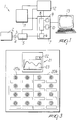
- the reference numeral 1 designates the device according to the present invention.
- the reference numeral 2 designates the probe for measuring the clarity of the purified water; said probe is normally immersed in the output water of the purifying plant.
- the output of the measurement probe is constituted by a first illuminating optical fiber 3 and by a second return optical fiber 4.
- the probe 2 comprises the two optical fibers 3 and 4, which are joined in a single input/output terminal 14.
- a reflector 15 is arranged in front of the terminal 14 and reflects the light signal from the first optical fiber 3 towards the inlet of the second optical fiber 4. The inclination of the reflector 15 is calibrated so as to obtain an optimum response light signal.
- the optical fibers 3 and 4, the terminal 14 and the reflector 15 are mounted on a rigid support 19 made of stainless steel.
- the probe 2 is furthermore placed in a chamber 16 that has a water inlet 17 and a water outlet 18.
- the chamber 16, containing the probe 2 is immersed in the water leaving the purification plant.
- the openings 17 and 18 allow circulation of the water inside the chamber 16 and between the terminal 14 and the reflector 15.
- the two optical fibers 3 and 4 are connected to a photocell unit 5, which emits the light signal, by means of a built-in fluorescent lamp, for the first optical fiber 3 and measures the signal arriving from the second optical fiber 4.
- the photocell unit 5 furthermore converts the difference between the emitted light signal and the received light signal into an analog DC signal on the order of 4-20 mA, according to the difference measured. This difference between the light signals is proportional to the clarity of the water in which the measurement probe is immersed.
- the output of the photocell unit 5 is sent to an analog-digital converter 6 which is included in monitoring means 7.
- the converter 6 converts the analog signal arriving from the photocell unit 5 into a digital signal that can be read by a microprocessor 8 of the monitoring means 7.
- the microprocessor is furthermore provided with a random-access memory 9 and with a wave-shaping circuit 10.
- Visualization means constituted by a panel 11 provided with LEDs and with an X-Y recorder, are driven by the monitoring means 7.
- a power supply unit 12 which is supplied at mains voltage, is connected to the photocell unit 5, to the monitoring means 7 and to the visualization panel 11 so that they are supplied with low-voltage power.
- an external computer 13 is connected to the monitoring means 7.
- Such computer may be an IBM PC compatible computer which has an Intel 80386 processor and 2Mb of RAM, an interace card.
- the computer 13 may be supplied with a printer which prints the required data (plant, year, month, day, hour, minutes, % of probability, graphs). Such data may also be stored on the hard disk or diskettes of the PC 13.
- the microprocessor 8, or the computer 13 provide the data related to reliability to make the purified water fall within the limits set by the applicable statutory provisions with a clarity reading.
- This last equation has the purpose of correlating the various clarity readings Xo measured on the samples with the reading X1 related to the sample diluted or concentrated by the factor Y1.
- the following table shows an example of the percentages of reliability for a group of plants.
- the clarity value of 95 is the value for distilled water.
- the table calculated and stored by the microprocessor 8 and/or computer 13 allows to obtain the percentages of reliability for the individual substances: if the clarity reading is 50, there is a 38% possibility that BOD5 is within Table A of Law no. 316/76, a 77% probability for COD, and 98% for total reduced nitrogen Kj (TOTAL NITR. Kj).
- the water entering purification plants whether diluted or not, usually has higher reliability percentages.
- the microprocessor 8 can determine the percentages of reliability of the water in which the measurement probe 2 is immersed.
- the visualization means 11, shown in figure 3, include a plurality of light-emitting diodes (LED), divided into two sections 20a and 20b.
- LED light-emitting diodes
- Each diode of each section corresponds to a particular substance for which the reliability percentage is measured, so that each substance has two diodes divided between the two sections 20a and 20b.
- the diodes of the section 20a visualize that a particular substance is within the reliability limit, whereas the diodes of the section 20b visualize that a particular substance exceeds the reliability limit.
- the diodes of the two sections preferably have different colors.
- a recorder 21 is included in the visualization means 11.
- the recorder 21 comprises a digital display 22 which displays a single percentage (the "grade") of the purified water.
- the recorder furthermore has an X-Y display 23 that can display the trend of this single percentage over time.
- Such results may be displayed on the screen of the computer 13.
- the measurement probe 2 together with its chamber 16, is immersed in the water to be monitored of the purification plant (typically at a depth between 15 and 100cm). Due to the current, the water of the purification plant is forced into the chamber 16 of the measurement probe by means of the inlet 17. In the same manner, the water can freely flow out of the chamber 16 through the outlet 18, thus allowing the water to be monitored to circulate inside the chamber 16 and between the reflector 15 and the terminal 14 of the two optical fibers.
- the photocell unit sends, by means of the built-in fluorescent lamp, a light beam over the first optical fiber 3.
- the light beam is reflected by the reflector 15 and returns to the photocell unit 5 over the second optical fiber 4.
- the reflected light beam is weaker than the transmitted beam, since the particles suspended and dissolved in the water interfere and scatter part of the light beam.
- the reflected beam that returns to the photocell unit 5 is thus weaker than the emitted one.
- the amount of scattered light depends on the size, concentration and composition of the dissolved or suspended particles that are present.
- the difference between the emitted light beam and the reflected one is measured by the unit 5 and converted into a DC signal.
- This signal is sent to the A/D converter 6, which converts it into a numeral corresponding to the clarity of the measured liquid, which is comprised between a minimum value and a maximum value that are set on a scale chosen at will (for example from 0 to 100).
- the monitoring means 7 then switch on the diodes of the visualization means 11 as a function of the reliability percentage measured from water clarity.
- the monitoring means 7 are set so that the diodes of section 20a switch on only when the reliability percentages exceed a certain threshold (for example 90%).
- the thresholds are set according to the accuracy (reliability) of the table stored in the memory 9.
- the accuracy of the table i.e. the closeness of the reliability percentages to 100%, is improved by updating with data from new analyses, as described above. Furthermore, by checking clarity readings against analyses it is possible to build percentage curves for the individual substances for each plant, increasing reliability of said readings.
- the appropriately provided diode of the section 20a switches on; if a particular substance instead exceeds the reliability limit, the related diode of the section 20b switches on.
- microprocessor 8 or the computer 13 calculates a single water reliability percentage which is displayed on the digital display 22 of the recorder. This numeral is considered as the quality "grade" assigned to the water to be monitored.
- the X-Y display 23 visualizes the trend of this single percentage (the "grade") over time.
- the quality of the water can be measured continuously, obtaining round-the-clock monitoring.
- the probe may be supplied with pneumatic cleaning means which may clean the interior of the chamber 16 and in particular the space between the reflector 15 and the two optical fibers 3 and 4.
- the device according to the present invention can be used in other applications, such as the continuous monitoring of lakes and rivers.
Landscapes
- Health & Medical Sciences (AREA)
- Life Sciences & Earth Sciences (AREA)
- Chemical & Material Sciences (AREA)
- Biochemistry (AREA)
- General Physics & Mathematics (AREA)
- Medicinal Chemistry (AREA)
- Physics & Mathematics (AREA)
- Analytical Chemistry (AREA)
- Engineering & Computer Science (AREA)
- General Health & Medical Sciences (AREA)
- Food Science & Technology (AREA)
- Immunology (AREA)
- Pathology (AREA)
- Hydroponics (AREA)
- Investigating Or Analysing Materials By Optical Means (AREA)
- Activated Sludge Processes (AREA)
- Investigating, Analyzing Materials By Fluorescence Or Luminescence (AREA)
- Fertilizers (AREA)
Applications Claiming Priority (2)
| Application Number | Priority Date | Filing Date | Title |
|---|---|---|---|
| ITMI931547 | 1993-07-14 | ||
| IT93MI001547A IT1264931B1 (it) | 1993-07-14 | 1993-07-14 | Dispositivo per il controllo della qualita' di acque depurate particolarmente per impianti biologici di depurazione e simili |
Publications (3)
| Publication Number | Publication Date |
|---|---|
| EP0634654A2 true EP0634654A2 (de) | 1995-01-18 |
| EP0634654A3 EP0634654A3 (de) | 1995-10-04 |
| EP0634654B1 EP0634654B1 (de) | 1999-08-18 |
Family
ID=11366602
Family Applications (1)
| Application Number | Title | Priority Date | Filing Date |
|---|---|---|---|
| EP94110344A Expired - Lifetime EP0634654B1 (de) | 1993-07-14 | 1994-07-04 | Vorrichtung zur Kontrolle der Wasserqualität, insbesondere für biologische Kläranlagen |
Country Status (5)
| Country | Link |
|---|---|
| EP (1) | EP0634654B1 (de) |
| AT (1) | ATE183585T1 (de) |
| DE (1) | DE69420089T2 (de) |
| ES (1) | ES2138015T3 (de) |
| IT (1) | IT1264931B1 (de) |
Cited By (4)
| Publication number | Priority date | Publication date | Assignee | Title |
|---|---|---|---|---|
| US6953550B2 (en) | 1996-12-20 | 2005-10-11 | Tecan Trading Ag | Affinity binding-based system for detecting particulates in a fluid |
| EP1194774A4 (de) * | 1999-05-19 | 2009-03-11 | Itt Mfg Enterprises Inc | Wasserprobenahme mit analyt extraktion - und integrierung |
| US8951783B2 (en) | 2010-04-07 | 2015-02-10 | Jaydeep BHATTACHARYA | Detector for chemical compounds |
| CN107364550A (zh) * | 2017-06-26 | 2017-11-21 | 中国水产科学研究院淡水渔业研究中心 | 渔业水质在线自动检测船 |
Families Citing this family (1)
| Publication number | Priority date | Publication date | Assignee | Title |
|---|---|---|---|---|
| IT202100028064A1 (it) | 2021-11-04 | 2023-05-04 | Arcangelo Ventura | Dispositivo per la misura automatica della velocita' di sedimentazione e del volume del fango. |
Family Cites Families (6)
| Publication number | Priority date | Publication date | Assignee | Title |
|---|---|---|---|---|
| FR2583164B1 (fr) * | 1985-06-06 | 1988-10-14 | Trapil Transports Petroliers P | Procede et dispositif pour determiner la couleur et la turbidite d'un fluide |
| US4893935A (en) * | 1988-08-19 | 1990-01-16 | Mandel William R | Apparatus and method for optical density measurements of biomass processes |
| CA1311625C (en) * | 1988-09-30 | 1992-12-22 | Claritek Research & Engineering Co. | Turbidity meter |
| US5242602A (en) * | 1992-03-04 | 1993-09-07 | W. R. Grace & Co.-Conn. | Spectrophotometric monitoring of multiple water treatment performance indicators using chemometrics |
| DE9216020U1 (de) * | 1992-03-28 | 1993-03-11 | W & U Steuerungstechnik GmbH, 4005 Meerbusch | Vorrichtung zum Überwachen eines Mediums bezüglich umweltrelevanter Vorgänge |
| DE9319750U1 (de) * | 1993-12-22 | 1994-02-17 | Hellma GmbH u.Co KG Glastechnische-optische Werkstätten, 79379 Müllheim | Meßvorrichtung, bei welcher ein Lichtstrahl durch ein flüssiges Medium geleitet wird |
-
1993
- 1993-07-14 IT IT93MI001547A patent/IT1264931B1/it active IP Right Grant
-
1994
- 1994-07-04 EP EP94110344A patent/EP0634654B1/de not_active Expired - Lifetime
- 1994-07-04 DE DE69420089T patent/DE69420089T2/de not_active Expired - Fee Related
- 1994-07-04 ES ES94110344T patent/ES2138015T3/es not_active Expired - Lifetime
- 1994-07-04 AT AT94110344T patent/ATE183585T1/de active
Cited By (5)
| Publication number | Priority date | Publication date | Assignee | Title |
|---|---|---|---|---|
| US6953550B2 (en) | 1996-12-20 | 2005-10-11 | Tecan Trading Ag | Affinity binding-based system for detecting particulates in a fluid |
| EP1194774A4 (de) * | 1999-05-19 | 2009-03-11 | Itt Mfg Enterprises Inc | Wasserprobenahme mit analyt extraktion - und integrierung |
| US8951783B2 (en) | 2010-04-07 | 2015-02-10 | Jaydeep BHATTACHARYA | Detector for chemical compounds |
| CN107364550A (zh) * | 2017-06-26 | 2017-11-21 | 中国水产科学研究院淡水渔业研究中心 | 渔业水质在线自动检测船 |
| CN107364550B (zh) * | 2017-06-26 | 2023-05-19 | 中国水产科学研究院淡水渔业研究中心 | 渔业水质在线自动检测船 |
Also Published As
| Publication number | Publication date |
|---|---|
| ITMI931547A0 (it) | 1993-07-14 |
| EP0634654B1 (de) | 1999-08-18 |
| IT1264931B1 (it) | 1996-10-17 |
| ATE183585T1 (de) | 1999-09-15 |
| EP0634654A3 (de) | 1995-10-04 |
| ES2138015T3 (es) | 2000-01-01 |
| DE69420089D1 (de) | 1999-09-23 |
| ITMI931547A1 (it) | 1995-01-14 |
| DE69420089T2 (de) | 2000-02-10 |
Similar Documents
| Publication | Publication Date | Title |
|---|---|---|
| US4119860A (en) | Fluid measurement | |
| WO1992016828A2 (en) | Organic pollutant monitor | |
| US6803594B2 (en) | Measuring system for optically determining concentration of turbid liquid samples | |
| ATE119789T1 (de) | Anzeigevorrichtung für das vorhandensein eines schlauches und/oder von flüssigkeit darin. | |
| US4078863A (en) | Measuring the concentration of substances suspended in a liquid | |
| EP0634654B1 (de) | Vorrichtung zur Kontrolle der Wasserqualität, insbesondere für biologische Kläranlagen | |
| AU638718B2 (en) | Apparatus for detection of microorganisms | |
| NL8301928A (nl) | Inrichting voor het bepalen van het troebelingspunt. | |
| US3441737A (en) | Radiation sensitive sludge level testing device | |
| ATE170380T1 (de) | Fluoreszenzmesser für augenuntersuchungen | |
| US7046347B1 (en) | Instrument with colorimeter and sensor inputs for interfacing with a computer | |
| US5694206A (en) | Spectrophotometric system using a pH/ISE meter for calibration | |
| EP0185285A2 (de) | Messapparat für Flüssigkeitspegel | |
| US6195160B1 (en) | Illuminating means for refractometer | |
| AU590223B2 (en) | Concentration meter | |
| KR20090017902A (ko) | 탁도계 | |
| EP0207498A2 (de) | Spektrophotometer | |
| Nayeem et al. | Towards development of a simple technique based on wavelength specific absorption for quality measurement of flowing water | |
| US7055257B2 (en) | Lighted fish measurement device | |
| GB2373852A (en) | Porable light detector | |
| Elliott | Turbidity: the final element in assessing water quality | |
| EP4538679A1 (de) | Messung der optischen eigenschaften eines fluids | |
| US2915938A (en) | Electronic colorimeter | |
| CA1183367A (en) | Optical analyzing method and system | |
| JP2965939B2 (ja) | 残留塩素計 |
Legal Events
| Date | Code | Title | Description |
|---|---|---|---|
| PUAI | Public reference made under article 153(3) epc to a published international application that has entered the european phase |
Free format text: ORIGINAL CODE: 0009012 |
|
| AK | Designated contracting states |
Kind code of ref document: A2 Designated state(s): AT CH DE ES FR GB GR IT LI |
|
| PUAL | Search report despatched |
Free format text: ORIGINAL CODE: 0009013 |
|
| AK | Designated contracting states |
Kind code of ref document: A3 Designated state(s): AT CH DE ES FR GB GR IT LI |
|
| 17P | Request for examination filed |
Effective date: 19960329 |
|
| 17Q | First examination report despatched |
Effective date: 19970922 |
|
| GRAG | Despatch of communication of intention to grant |
Free format text: ORIGINAL CODE: EPIDOS AGRA |
|
| GRAG | Despatch of communication of intention to grant |
Free format text: ORIGINAL CODE: EPIDOS AGRA |
|
| GRAH | Despatch of communication of intention to grant a patent |
Free format text: ORIGINAL CODE: EPIDOS IGRA |
|
| GRAH | Despatch of communication of intention to grant a patent |
Free format text: ORIGINAL CODE: EPIDOS IGRA |
|
| GRAA | (expected) grant |
Free format text: ORIGINAL CODE: 0009210 |
|
| AK | Designated contracting states |
Kind code of ref document: B1 Designated state(s): AT CH DE ES FR GB GR IT LI |
|
| PG25 | Lapsed in a contracting state [announced via postgrant information from national office to epo] |
Ref country code: GR Free format text: LAPSE BECAUSE OF NON-PAYMENT OF DUE FEES Effective date: 19990818 Ref country code: AT Free format text: LAPSE BECAUSE OF FAILURE TO SUBMIT A TRANSLATION OF THE DESCRIPTION OR TO PAY THE FEE WITHIN THE PRESCRIBED TIME-LIMIT Effective date: 19990818 |
|
| REF | Corresponds to: |
Ref document number: 183585 Country of ref document: AT Date of ref document: 19990915 Kind code of ref document: T |
|
| REG | Reference to a national code |
Ref country code: CH Ref legal event code: EP |
|
| REF | Corresponds to: |
Ref document number: 69420089 Country of ref document: DE Date of ref document: 19990923 |
|
| ITF | It: translation for a ep patent filed | ||
| ET | Fr: translation filed | ||
| REG | Reference to a national code |
Ref country code: CH Ref legal event code: NV Representative=s name: ROTTMANN, ZIMMERMANN + PARTNER AG |
|
| REG | Reference to a national code |
Ref country code: ES Ref legal event code: FG2A Ref document number: 2138015 Country of ref document: ES Kind code of ref document: T3 |
|
| PLBE | No opposition filed within time limit |
Free format text: ORIGINAL CODE: 0009261 |
|
| STAA | Information on the status of an ep patent application or granted ep patent |
Free format text: STATUS: NO OPPOSITION FILED WITHIN TIME LIMIT |
|
| 26N | No opposition filed | ||
| REG | Reference to a national code |
Ref country code: GB Ref legal event code: IF02 |
|
| PGFP | Annual fee paid to national office [announced via postgrant information from national office to epo] |
Ref country code: ES Payment date: 20080627 Year of fee payment: 15 |
|
| PGFP | Annual fee paid to national office [announced via postgrant information from national office to epo] |
Ref country code: IT Payment date: 20080620 Year of fee payment: 15 |
|
| PGFP | Annual fee paid to national office [announced via postgrant information from national office to epo] |
Ref country code: CH Payment date: 20080709 Year of fee payment: 15 Ref country code: DE Payment date: 20080908 Year of fee payment: 15 |
|
| PGFP | Annual fee paid to national office [announced via postgrant information from national office to epo] |
Ref country code: FR Payment date: 20080625 Year of fee payment: 15 |
|
| PGFP | Annual fee paid to national office [announced via postgrant information from national office to epo] |
Ref country code: GB Payment date: 20080729 Year of fee payment: 15 |
|
| REG | Reference to a national code |
Ref country code: CH Ref legal event code: PL |
|
| GBPC | Gb: european patent ceased through non-payment of renewal fee |
Effective date: 20090704 |
|
| REG | Reference to a national code |
Ref country code: FR Ref legal event code: ST Effective date: 20100331 |
|
| PG25 | Lapsed in a contracting state [announced via postgrant information from national office to epo] |
Ref country code: LI Free format text: LAPSE BECAUSE OF NON-PAYMENT OF DUE FEES Effective date: 20090731 Ref country code: FR Free format text: LAPSE BECAUSE OF NON-PAYMENT OF DUE FEES Effective date: 20090731 Ref country code: CH Free format text: LAPSE BECAUSE OF NON-PAYMENT OF DUE FEES Effective date: 20090731 |
|
| PG25 | Lapsed in a contracting state [announced via postgrant information from national office to epo] |
Ref country code: GB Free format text: LAPSE BECAUSE OF NON-PAYMENT OF DUE FEES Effective date: 20090704 |
|
| PG25 | Lapsed in a contracting state [announced via postgrant information from national office to epo] |
Ref country code: DE Free format text: LAPSE BECAUSE OF NON-PAYMENT OF DUE FEES Effective date: 20100202 |
|
| REG | Reference to a national code |
Ref country code: ES Ref legal event code: FD2A Effective date: 20090706 |
|
| PG25 | Lapsed in a contracting state [announced via postgrant information from national office to epo] |
Ref country code: ES Free format text: LAPSE BECAUSE OF NON-PAYMENT OF DUE FEES Effective date: 20090706 |
|
| PG25 | Lapsed in a contracting state [announced via postgrant information from national office to epo] |
Ref country code: IT Free format text: LAPSE BECAUSE OF NON-PAYMENT OF DUE FEES Effective date: 20090704 |