EP0634773A1 - Tube à rayons cathodiques - Google Patents
Tube à rayons cathodiques Download PDFInfo
- Publication number
- EP0634773A1 EP0634773A1 EP94201950A EP94201950A EP0634773A1 EP 0634773 A1 EP0634773 A1 EP 0634773A1 EP 94201950 A EP94201950 A EP 94201950A EP 94201950 A EP94201950 A EP 94201950A EP 0634773 A1 EP0634773 A1 EP 0634773A1
- Authority
- EP
- European Patent Office
- Prior art keywords
- electrodes
- connecting elements
- cathode ray
- ray tube
- electron gun
- Prior art date
- Legal status (The legal status is an assumption and is not a legal conclusion. Google has not performed a legal analysis and makes no representation as to the accuracy of the status listed.)
- Granted
Links
- 238000010894 electron beam technology Methods 0.000 claims description 7
- 239000011810 insulating material Substances 0.000 claims description 2
- 230000005684 electric field Effects 0.000 description 3
- 239000011521 glass Substances 0.000 description 3
- OAICVXFJPJFONN-UHFFFAOYSA-N Phosphorus Chemical compound [P] OAICVXFJPJFONN-UHFFFAOYSA-N 0.000 description 2
- 230000002411 adverse Effects 0.000 description 2
- 238000004519 manufacturing process Methods 0.000 description 2
- 239000002245 particle Substances 0.000 description 2
- 238000001816 cooling Methods 0.000 description 1
- 230000000694 effects Effects 0.000 description 1
- 238000010438 heat treatment Methods 0.000 description 1
- 238000000034 method Methods 0.000 description 1
- 238000003825 pressing Methods 0.000 description 1
Images

Classifications
-
- H—ELECTRICITY
- H01—ELECTRIC ELEMENTS
- H01J—ELECTRIC DISCHARGE TUBES OR DISCHARGE LAMPS
- H01J29/00—Details of cathode-ray tubes or of electron-beam tubes of the types covered by group H01J31/00
- H01J29/46—Arrangements of electrodes and associated parts for generating or controlling the ray or beam, e.g. electron-optical arrangement
- H01J29/48—Electron guns
-
- H—ELECTRICITY
- H01—ELECTRIC ELEMENTS
- H01J—ELECTRIC DISCHARGE TUBES OR DISCHARGE LAMPS
- H01J29/00—Details of cathode-ray tubes or of electron-beam tubes of the types covered by group H01J31/00
- H01J29/46—Arrangements of electrodes and associated parts for generating or controlling the ray or beam, e.g. electron-optical arrangement
- H01J29/82—Mounting, supporting, spacing, or insulating electron-optical or ion-optical arrangements
Definitions
- the invention relates to a cathode ray tube comprising a display screen and an electron gun having a means for generating electrons, a number of electrodes and a support which is composed of an insulating material, said electrodes being provided with connecting elements which are secured in the support.
- Cathode ray tubes are used, inter alia , in television receivers, computer monitors, oscilloscopes etc .
- a cathode ray tube of the class mentioned in the opening paragraph is of the conventional type.
- the electron gun comprises a means for generating electrons, for example a cathode.
- the electrodes are provided with connecting elements which are pressed into the support.
- the support is generally made from glass which can be softened.
- the electrodes of the electron gun are stacked on top of each other, whereafter the support is (or are, if more than one support is used) heated. By virtue thereof, the support and the projections can be interconnected. This is generally achieved by pressing the support against the projections. Since the glass has been softened by heating, the connecting elements can be inserted into the support.
- the connecting elements may be integral with the electrode or they may be secured to the electrode as a separate part. After cooling, the electrodes and the support are secured to each other.
- the cathode ray tube in accordance with the invention is characterized in that the electron gun comprises a pair of electrodes which are arranged one behind the other, said electrodes having connecting elements extending in a plane transverse to the electron beam, the width of the connecting elements of one of the electrodes of the pair of electrodes differing from the width of the connecting elements of the other electrode of the pair of electrodes.
- the connecting elements of successive electrodes are of equal width.
- the invention is inter alia based on the insight that electrons can readily hop from one electrode to a proximate electrode via a connecting element and to a connecting element of a nearby electrode via the support, and that in this process the edges of the connecting elements form an important source of electrons.
- the width of the connecting elements By varying the width of the connecting elements, the shortest distance, via the support, between the edge of a connecting element and the next electrode is increased.
- the cathode ray tube comprises means for applying voltages to the pair of electrodes, and the voltage applied to the electrode having the widest connecting elements is lower than the voltage applied to the electrode having the narrowest connecting elements.
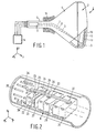
- Fig. 1 is a partly perspective view of a cathode ray tube 1.
- Said cathode ray tube 1 comprises an evacuated envelope 2 having a display window 3, a cone 4 and a neck 5.
- an electron gun 6 for generating, in this example, three electron beams 7, 8 and 9.
- a luminescent display screen 10 which, in this example, comprises phosphor elements luminescing in red, green and blue is situated on the inside of the display window 3.
- the electron beams 7, 8 and 9 are deflected across the screen 10 by means of a deflection unit 11 which is located at the junction between the neck and the cone, and pass through the shadow mask 12 which comprises a thin plate having apertures 13.
- the electron beams 7, 8 and 9 pass through the apertures 13 at a small angle with respect to each other and each electron beam impinges on phosphor elements of only one colour.
- the means 14 for applying voltages to the electrodes of the electron gun are also diagrammatically shown.
- Fig. 2 is a diagrammatic, partly perspective view of an electron gun 6.
- Electron gun 6 comprises a common control electrode 21, also referred to as G1 electrode, in which three cathodes 22, 23 and 24 are secured.
- the G1 electrode is secured to supports 26 by means of connecting elements 25.
- Said supports are made of glass.
- An example of such supports are the supports which are commonly referred to as "beading rods".
- the electron gun 6 further comprises a common plate-shaped electrode 27, also referred to as G2 electrode, which is secured to the supports by connecting elements 28.
- the electron gun 6 comprises two supports 26. One of said supports is shown, the other is situated on the side of the electron gun 6 which is invisible in this perspective view.
- the electron gun 6 further comprises the common electrodes 29 and 31 which are also secured to supports 26 by means of connecting elements (30 and 32, respectively).
- the supports are secured on feed-through pins 35 by means of brackets 34. The electrical connections between the feed-through pins and the electrodes are not shown.
- Figs. 3A and 3B are side views of a detail of the electron gun 6. Electrodes 36 and 37 are secured in the support 26 by means of securing elements 38 and 39. Said securing elements 38 and 39 are shown in detail in Fig. 3B.
- the width of the securing element 39 exceeds that of securing element 38, for example 8 mm (securing element 39) and 5 mm (securing element 38).
- the distance between the electrodes (in the z-direction) is approximately 1.5 mm.
- the voltage applied to electrode 37 is lower than the voltage applied to electrode 36, during operation. Due to this, an electric field is generated between the electrodes. This electric field may cause electrons to hop from electrode 37 to electrode 36.
- FIG. 4 diagrammatically shows a detail of a further example of an electron gun for a cathode ray tube in accordance with the invention.
- This electron gun comprises a stack of 4 electrodes 41, 42, 43 and 44 having securing elements 41A, 42A, 43A and 44A, respectively.
- voltages V1 and V2 (V1 ⁇ V2) are applied to the electrodes, V1 being applied to electrodes 41 and 43 and V2 being applied to electrodes 42 and 44.
- the width of the connecting elements 41A and 43A is greater than the width of the connecting elements 42A and 44A.
- the widths are 8 mm (41A and 43A) and 5 mm (42A and 44A), respectively.
- the difference in width between the connecting elements is greater than the distance between the connecting elements, viewed along the electron beams.
- a further advantage is that sparking of the electron gun is enhanced.
- a customary step in the manufacture of an electron gun is the sparking of the electrodes. To this end, very high voltage differences between electrodes are generated. As a result, a flashover is generated between electrodes. By virtue thereof, burrs and loose particles are removed from the electrodes. Flashover between the connecting elements during sparking has two adverse effects. First, flashover between the electrodes does not take place or is less likely to take place and, second, loose particles can be formed. In a cathode ray tube in accordance with the invention, the risk of flashover between the connecting elements is reduced.
Landscapes
- Vessels, Lead-In Wires, Accessory Apparatuses For Cathode-Ray Tubes (AREA)
- Manufacture Of Electron Tubes, Discharge Lamp Vessels, Lead-In Wires, And The Like (AREA)
Applications Claiming Priority (2)
| Application Number | Priority Date | Filing Date | Title |
|---|---|---|---|
| BE9300720A BE1007285A3 (nl) | 1993-07-13 | 1993-07-13 | Kathodestraalbuis. |
| BE9300720 | 1993-07-13 |
Publications (2)
| Publication Number | Publication Date |
|---|---|
| EP0634773A1 true EP0634773A1 (fr) | 1995-01-18 |
| EP0634773B1 EP0634773B1 (fr) | 1998-10-07 |
Family
ID=3887177
Family Applications (1)
| Application Number | Title | Priority Date | Filing Date |
|---|---|---|---|
| EP94201950A Expired - Lifetime EP0634773B1 (fr) | 1993-07-13 | 1994-07-06 | Tube à rayons cathodiques |
Country Status (6)
| Country | Link |
|---|---|
| US (1) | US6653772B1 (fr) |
| EP (1) | EP0634773B1 (fr) |
| JP (1) | JP3735385B2 (fr) |
| KR (1) | KR100314690B1 (fr) |
| BE (1) | BE1007285A3 (fr) |
| DE (1) | DE69413755T2 (fr) |
Citations (3)
| Publication number | Priority date | Publication date | Assignee | Title |
|---|---|---|---|---|
| EP0104674A1 (fr) * | 1982-08-25 | 1984-04-04 | Koninklijke Philips Electronics N.V. | Tube-image couleur |
| FR2603135A1 (fr) * | 1986-08-21 | 1988-02-26 | Sony Corp | Canon electronique et procede pour son assemblage, applicables notamment a la fabrication de tubes cathodiques trichromes a canons en ligne |
| US4990822A (en) * | 1989-12-29 | 1991-02-05 | Zenith Electronics Corporation | Focusing electrode assembly for a color cathode ray tube electron gun |
Family Cites Families (18)
| Publication number | Priority date | Publication date | Assignee | Title |
|---|---|---|---|---|
| DE1097044B (de) * | 1959-11-24 | 1961-01-12 | Telefunken Gmbh | Elektrodensystem fuer Kathodenstrahlroehren |
| DE2526210A1 (de) * | 1975-06-12 | 1976-12-30 | Licentia Gmbh | Elektrodenanordnung fuer eine farbbildkathodenstrahlroehre |
| US4096408A (en) * | 1976-01-28 | 1978-06-20 | Zenith Radio Corporation | Unitized in-line electron gun having stress-absorbing electrode supports |
| CA1068323A (fr) * | 1976-02-05 | 1979-12-18 | Horst H. Blumenberg | Canon electronique unifie a electrodes avec tubes protecteurs de faisceaux |
| US4137480A (en) * | 1977-03-31 | 1979-01-30 | Zenith Radio Corporation | Television picture tube with cathode coating erosion suppression |
| US4181870A (en) * | 1978-03-08 | 1980-01-01 | Zenith Radio Corporation | Assembly of electron guns having different gamma values |
| US4485327A (en) * | 1978-10-18 | 1984-11-27 | Hitachi, Ltd. | Color picture tube |
| JPS56106352A (en) * | 1980-01-25 | 1981-08-24 | Hitachi Ltd | Electron gun frame for color picture tube |
| NL8102527A (nl) * | 1981-05-22 | 1982-12-16 | Philips Nv | Kleurenbeeldbuis. |
| JPS59148245A (ja) * | 1983-02-15 | 1984-08-24 | Nec Corp | 電子銃電極構体 |
| US4567400A (en) * | 1983-02-28 | 1986-01-28 | Rca Corporation | CRT Comprising metallized glass beads for suppressing arcing therein |
| JPS60105050U (ja) * | 1983-12-20 | 1985-07-17 | 三菱電機株式会社 | カラ−受像管 |
| US4595858A (en) * | 1984-12-03 | 1986-06-17 | Rca Corporation | Reinforcing means for a cup-shaped electron gun electrode |
| US4818912A (en) * | 1988-03-15 | 1989-04-04 | Rca Licensing Corporation | CRT with arc suppressing means on insulating support rods |
| JPH01255135A (ja) * | 1988-04-01 | 1989-10-12 | Nec Corp | インライン型電子銃 |
| NL9000943A (nl) * | 1990-04-20 | 1991-11-18 | Philips Nv | Kathodestraalbuis met elektronenkanon. |
| JPH0485557U (fr) * | 1990-11-30 | 1992-07-24 | ||
| DE69313399T2 (de) * | 1992-11-02 | 1998-02-26 | Philips Electronics Nv | Vacuumröhre mit keramischem Teil |
-
1993
- 1993-07-13 BE BE9300720A patent/BE1007285A3/nl not_active IP Right Cessation
-
1994
- 1994-07-06 DE DE69413755T patent/DE69413755T2/de not_active Expired - Fee Related
- 1994-07-06 EP EP94201950A patent/EP0634773B1/fr not_active Expired - Lifetime
- 1994-07-11 JP JP15863994A patent/JP3735385B2/ja not_active Expired - Fee Related
- 1994-07-12 US US08/273,672 patent/US6653772B1/en not_active Expired - Fee Related
- 1994-07-12 KR KR1019940016687A patent/KR100314690B1/ko not_active Expired - Fee Related
Patent Citations (3)
| Publication number | Priority date | Publication date | Assignee | Title |
|---|---|---|---|---|
| EP0104674A1 (fr) * | 1982-08-25 | 1984-04-04 | Koninklijke Philips Electronics N.V. | Tube-image couleur |
| FR2603135A1 (fr) * | 1986-08-21 | 1988-02-26 | Sony Corp | Canon electronique et procede pour son assemblage, applicables notamment a la fabrication de tubes cathodiques trichromes a canons en ligne |
| US4990822A (en) * | 1989-12-29 | 1991-02-05 | Zenith Electronics Corporation | Focusing electrode assembly for a color cathode ray tube electron gun |
Also Published As
| Publication number | Publication date |
|---|---|
| US6653772B1 (en) | 2003-11-25 |
| KR960015677A (ko) | 1996-05-22 |
| BE1007285A3 (nl) | 1995-05-09 |
| EP0634773B1 (fr) | 1998-10-07 |
| JP3735385B2 (ja) | 2006-01-18 |
| JPH0757656A (ja) | 1995-03-03 |
| DE69413755T2 (de) | 1999-05-20 |
| DE69413755D1 (de) | 1998-11-12 |
| KR100314690B1 (ko) | 2002-04-06 |
Similar Documents
| Publication | Publication Date | Title |
|---|---|---|
| US4629933A (en) | Cathode-ray tube having an electron gun with an astigmatic focusing grid | |
| EP0235975B1 (fr) | Tube à rayons cathodiques et dispositif d'affichage en couleurs | |
| US5347202A (en) | Display device and cathode ray tube | |
| EP0300704B1 (fr) | Tube image en couleur ayant un canon d'électrons en ligne avec une lentille unipotentielle | |
| US6271625B1 (en) | Picture display device provided with an electron gun, and electron gun for use in such a device | |
| EP0634773B1 (fr) | Tube à rayons cathodiques | |
| US4620134A (en) | Cathode-ray tube | |
| US4311944A (en) | CRT With dipolar deflection and quadrupolar-focusing color-selection structure | |
| EP0867035A1 (fr) | Appareil d'aspiration a dispositif getter | |
| US6580210B1 (en) | Method of manufacturing an electron gun, electron gun, display device with such an electron gun, and sub-assembly for use in such an electron gun | |
| EP0453039B1 (fr) | Tube à rayons cathodiques muni d'un canon à électrons | |
| US6509680B2 (en) | Electron gun display device provided with an electron gun | |
| EP0589522B1 (fr) | Tube à rayons cathodiques | |
| US4602186A (en) | Insulating mount for a CRT Einzel lens focus mask | |
| US4305018A (en) | Electron gun structure with electrical contact spring for color television display tube | |
| KR100719087B1 (ko) | 음극선관의 인-라인형 전자총 | |
| US5460559A (en) | Cathode ray tube | |
| US6744190B2 (en) | Cathode ray tube with modified in-line electron gun | |
| EP0725973B1 (fr) | Tube a rayons cathodiques equipe d'un canon electronique et systeme de lentille electrostatique | |
| EP0562682B1 (fr) | Tube image en couleur muni d'un canon à électrons | |
| US5448134A (en) | Cathode ray tube having improved structure for controlling image quality | |
| CN1328336A (zh) | 阴极射线管的电子枪 | |
| JPH09504646A (ja) | 電子銃を備える陰極線管及び静電レンズ系 |
Legal Events
| Date | Code | Title | Description |
|---|---|---|---|
| PUAI | Public reference made under article 153(3) epc to a published international application that has entered the european phase |
Free format text: ORIGINAL CODE: 0009012 |
|
| AK | Designated contracting states |
Kind code of ref document: A1 Designated state(s): DE FR GB NL |
|
| 17P | Request for examination filed |
Effective date: 19950718 |
|
| 17Q | First examination report despatched |
Effective date: 19960531 |
|
| GRAG | Despatch of communication of intention to grant |
Free format text: ORIGINAL CODE: EPIDOS AGRA |
|
| GRAG | Despatch of communication of intention to grant |
Free format text: ORIGINAL CODE: EPIDOS AGRA |
|
| GRAG | Despatch of communication of intention to grant |
Free format text: ORIGINAL CODE: EPIDOS AGRA |
|
| GRAH | Despatch of communication of intention to grant a patent |
Free format text: ORIGINAL CODE: EPIDOS IGRA |
|
| GRAH | Despatch of communication of intention to grant a patent |
Free format text: ORIGINAL CODE: EPIDOS IGRA |
|
| GRAA | (expected) grant |
Free format text: ORIGINAL CODE: 0009210 |
|
| AK | Designated contracting states |
Kind code of ref document: B1 Designated state(s): DE FR GB NL |
|
| PG25 | Lapsed in a contracting state [announced via postgrant information from national office to epo] |
Ref country code: NL Free format text: LAPSE BECAUSE OF FAILURE TO SUBMIT A TRANSLATION OF THE DESCRIPTION OR TO PAY THE FEE WITHIN THE PRESCRIBED TIME-LIMIT Effective date: 19981007 |
|
| REF | Corresponds to: |
Ref document number: 69413755 Country of ref document: DE Date of ref document: 19981112 |
|
| ET | Fr: translation filed | ||
| NLV1 | Nl: lapsed or annulled due to failure to fulfill the requirements of art. 29p and 29m of the patents act | ||
| PLBE | No opposition filed within time limit |
Free format text: ORIGINAL CODE: 0009261 |
|
| STAA | Information on the status of an ep patent application or granted ep patent |
Free format text: STATUS: NO OPPOSITION FILED WITHIN TIME LIMIT |
|
| 26N | No opposition filed | ||
| REG | Reference to a national code |
Ref country code: GB Ref legal event code: IF02 |
|
| PGFP | Annual fee paid to national office [announced via postgrant information from national office to epo] |
Ref country code: GB Payment date: 20050727 Year of fee payment: 12 |
|
| PGFP | Annual fee paid to national office [announced via postgrant information from national office to epo] |
Ref country code: FR Payment date: 20050729 Year of fee payment: 12 |
|
| PGFP | Annual fee paid to national office [announced via postgrant information from national office to epo] |
Ref country code: DE Payment date: 20050913 Year of fee payment: 12 |
|
| PG25 | Lapsed in a contracting state [announced via postgrant information from national office to epo] |
Ref country code: GB Free format text: LAPSE BECAUSE OF NON-PAYMENT OF DUE FEES Effective date: 20060706 |
|
| PG25 | Lapsed in a contracting state [announced via postgrant information from national office to epo] |
Ref country code: DE Free format text: LAPSE BECAUSE OF NON-PAYMENT OF DUE FEES Effective date: 20070201 |
|
| GBPC | Gb: european patent ceased through non-payment of renewal fee |
Effective date: 20060706 |
|
| REG | Reference to a national code |
Ref country code: FR Ref legal event code: ST Effective date: 20070330 |
|
| PG25 | Lapsed in a contracting state [announced via postgrant information from national office to epo] |
Ref country code: FR Free format text: LAPSE BECAUSE OF NON-PAYMENT OF DUE FEES Effective date: 20060731 |