EP0634977B1 - Dispositif pour classer des feuilles volantes - Google Patents
Dispositif pour classer des feuilles volantes Download PDFInfo
- Publication number
- EP0634977B1 EP0634977B1 EP93909040A EP93909040A EP0634977B1 EP 0634977 B1 EP0634977 B1 EP 0634977B1 EP 93909040 A EP93909040 A EP 93909040A EP 93909040 A EP93909040 A EP 93909040A EP 0634977 B1 EP0634977 B1 EP 0634977B1
- Authority
- EP
- European Patent Office
- Prior art keywords
- hinge
- spine
- locking member
- tongue
- members
- Prior art date
- Legal status (The legal status is an assumption and is not a legal conclusion. Google has not performed a legal analysis and makes no representation as to the accuracy of the status listed.)
- Expired - Lifetime
Links
- 230000037431 insertion Effects 0.000 claims description 3
- 238000003780 insertion Methods 0.000 claims description 3
- 230000002401 inhibitory effect Effects 0.000 claims 1
- 239000000463 material Substances 0.000 description 4
- 238000000465 moulding Methods 0.000 description 4
- 239000004033 plastic Substances 0.000 description 3
- 229920003023 plastic Polymers 0.000 description 3
- 239000011230 binding agent Substances 0.000 description 2
- 230000036316 preload Effects 0.000 description 2
- 238000004080 punching Methods 0.000 description 2
- 230000035939 shock Effects 0.000 description 2
- 239000004743 Polypropylene Substances 0.000 description 1
- 238000006073 displacement reaction Methods 0.000 description 1
- 238000005553 drilling Methods 0.000 description 1
- 230000000694 effects Effects 0.000 description 1
- 229920002457 flexible plastic Polymers 0.000 description 1
- 230000013011 mating Effects 0.000 description 1
- 239000002184 metal Substances 0.000 description 1
- -1 polypropylene Polymers 0.000 description 1
- 229920001155 polypropylene Polymers 0.000 description 1
- 238000000926 separation method Methods 0.000 description 1
Images

Classifications
-
- B—PERFORMING OPERATIONS; TRANSPORTING
- B42—BOOKBINDING; ALBUMS; FILES; SPECIAL PRINTED MATTER
- B42F—SHEETS TEMPORARILY ATTACHED TOGETHER; FILING APPLIANCES; FILE CARDS; INDEXING
- B42F13/00—Filing appliances with means for engaging perforations or slots
- B42F13/16—Filing appliances with means for engaging perforations or slots with claws or rings
- B42F13/20—Filing appliances with means for engaging perforations or slots with claws or rings pivotable about an axis or axes parallel to binding edges
- B42F13/22—Filing appliances with means for engaging perforations or slots with claws or rings pivotable about an axis or axes parallel to binding edges in two sections engaging each other when closed
- B42F13/26—Filing appliances with means for engaging perforations or slots with claws or rings pivotable about an axis or axes parallel to binding edges in two sections engaging each other when closed and locked when so engaged, e.g. snap-action
Definitions
- This invention relates to a device for looseleaf binding of papers and documents.
- a secondary object of this invention is to provide flexibility of use by permitting the binding of covers as well as pages, so that the covers and not the binding means relate to the content of the assembled document, allowing the use of one looseleaf binding means for a range of documents.
- Looseleaf binding devices are shown in US-A-3057357 and US-A-3183913.
- Several embodiments of device are shown in US-A-3057357 but all are either complex integral mouldings or are assembled from separate components utilizing ball-and-socket type joints.
- the ball-and-socket embodiments avoid the problems of the relatively complex tooling necessary to produce the moulded embodiments, the ball-and-socket arrangements are not well adapted to resisting shock loading as would occur if a sheaf of bound documents is dropped. Under such loading conditions the ball will tend to pop out of the corresponding socket with the resultant failure of the device.
- the device of US-A-3183913 requires, in addition to two separate spine members, a base member which holds the spine members and controls movement thereof. This additional component adds to the cost and weight of the device. Also, the device illustrated is liable to snap over-centre into its release configuration in the event of shock loading of the type referred to above.
- the present invention provides a looseleaf binding device of the type referred to in the pre-characterising portion of claim 1 which is characterised in that the interengaging components comprise a plurality of tongue-like projections formed integrally with one of the elongate members and a plurality of apertures defined by the other of the elongate members for receiving the tongue-like projections to secure the elongate members together.
- the tongue-like projections are each connected to the remainder of the elongate member with which they are formed by means of hinge portions, the hinge portions of the tongue-like projections cooperating to form a hinge which permits articulation of the spine members relative to each other.
- the tongue-like projections each have a tapered lead-in region and a barb so that the tongue-like projections may readily be inserted into the corresponding apertures until the barbs snap behind the means defining the aperture. With this arrangement, the device may readily be assembled but is highly resistant to accidental disassembly.
- the locking member may comprise a strip slidable between the first and second extensions to hold the device in the closed configuration, but in a particularly preferred embodiment the locking member comprises a strip pivotably attached to one of the first and second extensions along one longitudinal edge of the strip, the strip being pivotable between a first, free position and a second locking position in which the strip engages with the other of the first and second extensions to hold the device in the closed configuration.
- the locking member is formed integrally with one of the elongate plastics members forming the spine or, in an alternative embodiment, integrally with the remainder of the device.
- the strip is provided with a tab for ease of movement between its first and second positions.
- a recess may be provided on the other of the first and second extensions such that the strip may be positively located in the locking position.
- the width of the locking member is such that when it is in its use position it somewhat elastically deforms one or both of the extensions and/or the first and/or second finger members so that the free ends of the finger members engage each other with a slight pre-load.
- the effect of this arrangement is to resist separation of the fingers and, and the same time, resist displacement of the locking strip from its use position.
- the spine is intended to be suitably sized to contain common sizes and volumes of looseleaf pages, and the number of finger means may be selected to form two or more closed loops as appropriate, depending on the number of holes provided in the pages.
- the shape and cross-section of the finger means may also be selected as appropriate for any particular application of the device.
- the binding device comprises a spine 2 which may be manufactured from a semi-flexible plastics material for example polypropylene.
- the spine 2 incorporates a longitudinal hinge 3 which may be formed by locally narrowing the thickness of the plastics material of the spine.
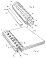
- a number of fingers 4 and 4a extend from the spine, on either side of the hinge 3, the fingers being integrally formed with the spine and being suitably sized and spaced to accept pre-punched pages 5, as shown in Figure 2.
- the device 1 is hingeable between a first, open position, illustrated in Figure 1, in which pre-punched pages 5 can be impaled over fingers 4a, for example, and a second, closed position illustrated in Figure 2, in which the free ends of the fingers 4 and 4a on either side of the hinge are brought together to hold the pages 5 on the closed loops formed by the cooperating fingers 4 and 4a.
- the free ends 6 of the fingers 4 and 4a may be formed with suitably shaped mating portions to provide positive cooperation between the fingers in the closed position.
- Two short extensions 7 and 7a are formed one on either side of the hinge 3 in spine 2.
- the extensions 7 and 7a project rearwardly from the spine, and the inside faces of these extensions are provided with grooves, formed to locate a locking member 8 which may be made of a thin strip of rigid material having a length similar to the spine.
- the locking member 11 is hingeable connected by a hinge 12 to the extension 7a.
- the locking member and hinge are formed integrally with the extension 7a.
- this locking member is in the position shown in broken line when the device is open.
- the locking member 11 can be pivoted in the direction of arrow 13 to snap into a recess on the interior face of extension 7 to hold the device in the closed position.
- the Figure 4 embodiment shows a spine which is constructed in two parts 14a and 14b held together by means of the hinge 15.
- Part 14b is formed with an enlarged edge 16 providing one part of the hinge
- part 14a is formed with a socket 17 along its edge, the socket 17 being adapted to fit around the enlarged edge 16 to provide the cooperating part of the hinge 15.
- the locking member 18 is formed integrally with extension 7 but in alternative arrangements the locking member may be formed integrally with extension 7a, or may provided as a separate slidably located locking strip.
- the locking member 18 is joined to extension 7 by a hinge 19 and is in a position similar to that shown in broken lines when the device is open.
- the locking member 18 When the device is closed, as shown in Figure 4, the locking member 18 can be pivoted in the direction of arrow 20 to lock between extensions 7 and 7a, and to clip into a recess on the interior face of extension 7a to positively locate the locking strip when the device is closed.
- one or more tabs 21 may be formed on the locking strip 6 so as to protrude from the outside face of extension 7a via one or more suitable slots provided in the extension 7a.
- the binding device is formed by two separate plastics mouldings 22, 23.
- Moulding 22 comprises extension 7, spine portion 14a and fingers 4.
- Moulding 23 comprises extension 7a, spine portion 14b, fingers 4a and locking member 18.
- Spine portion 14a has, integrally formed therewith, a plurality of tongue-like projections 24 each of which is connected by an integral hinge 25 to the spine portion 14a.
- An aperture corresponding to each tongue-like projection 24 is formed to one side of the spine portion 14b by a generally U-shaped bar 26 moulded integrally with the spine portion 14b.
- Each tongue-like projection 24 has a tapered lead-in region and a barb (as best seen in Figure 6) so that the tongue-like projections 24 may readily be inserted into the corresponding apertures until the barbs on the tongue-like projections snap under the bars 26. Thereafter, removal of the tongue-like projections from apertures will be very difficult.
- the locking member 18 of the embodiment of Figure 5 is formed in a manner similar to that of the embodiment of Figure 4, and operates in the same manner as that described above with reference to Figure 4.
- the device In the open position of the locking member, as shown in solid line in Figure 6, the device may be opened.
- the closed position of the locking member As shown in broken line, the edge of the locking member snaps into a groove 27 provided in the extension 7a to lock the device closed.
- hinging movement of the two portions of the device is accomplished by the hinged portions 25.
- the axial shape of the fingers 4 and 4a may be substantially semi-circular to form a circular loop when the device is closed, or the closed loop may be substantially square or rectangular, or may have any other suitable shape.
- the cross-section of the individual fingers 4 and 4a may be circular to suit generally available paper punching means, or may be rectangular, or any other suitable shape.
- the locking member should be removed (in the case of a separately formed strip) or released (in the case of an integral strip), and the fingers 4 and 4a of the binder opened by pressing together the extensions 7 and 7a formed on each side of the hinge at the rear of the spine.
- Pages formed with suitably sized and positioned holes can be impaled over the fingers.
- the binding device can be closed using pressure on the outer surfaces of the fingers.
- the binding device is positively locked in the closed position by inserting or positioning the locking member between the two extensions 7 and 7a formed at the rear of the spine so that the strip firmly bridges the gap across the hinge line and places the fingers under a slight preload. Pages are released by again removing or releasing the locking strip and opening the fingers.
Landscapes
- Sheet Holders (AREA)
Abstract
Claims (5)
- Un dispositif classeur pour feuilles volantes comportant: premier et second éléments dorsaux allongés formés séparément (14a, 14b) articulés l'un par rapport à l'autre et mutuellement raccordés par les composants respectifs à encliquetage (24, 26) des éléments dorsaux, une pluralité de premiers doigts (4) qui s'étendent vers l'avant à partir du premier élément dorsal (14a) d'un côté de la charnière (25); une pluralité de seconds doigts coopérants (4a) qui s'étendent vers l'avant à partir du deuxième élément dorsal (14b) de l'autre côté de la charnière (25); une première et une seconde extensions (7, 7a) qui font respectivement saillie vers l'arrière à partir des premier et second éléments dorsaux (14a, 14b) de part et d'autre de la charnière (25), le dispositif pouvant être déplacé au moyen de charnières entre une configuration ouverte dans laquelle les extrémités libres des doigts (4, 4a) sont espacées et une configuration fermée dans laquelle les extrémités libres des premier et second ensembles de doigts (4, 4a) se réunissent pour former une pluralité de boucles fermées à travers des trous dans une liasse de feuilles volantes à relier et dans laquelle la connexion formée par les éléments s'encliquetant mutuellement (24, 26) est sous contrainte de traction; et un élément de blocage (18) positionnable de manière à bloquer la première et la seconde extension (7, 7a) dans la position correspondant à la configuration fermée du dispositif afin de maintenir le dispositif en cette configuration fermée; caractérisé en ce que les dits éléments à encliquetage mutuel comportent une pluralité de projections en forme de languettes (24) formées intégralement avec l'un des éléments allongés (14a) et une pluralité d'ouvertures définies par le second des éléments allongés (14b) pour recevoir les dites projections semblables à des languettes (24) de manière à fixer ensemble les éléments allongés (14a, 14b), les dites projections en forme de languettes (24) étant chacune raccordées au reste des éléments allongés (14a) avec lesquels elles sont formées au moyen d'une partie articulée (25), les parties articulées des projections semblables à des languettes (24) coopérant pour former ladite charnière; et les dites projections semblables à des languettes (24) possédant chacune une région initiale conique et un picot de manière à ce que les projections en forme de languettes (24) puissent facilement être insérées dans les ouvertures correspondantes jusqu'à ce que les picots s'encliquent derrière les moyens (26) de définition des ouvertures, inhibant ainsi l'extraction des projections semblables à des languettes (24) hors des ouvertures.
- Un dispositif classeur selon la revendication 1, caractérisé en ce que chacune des dites ouvertures est formée en une barre généralement profilée en U (26) moulée intégralement avec une partie dorsale (14b) de son élément allongé associé (23).
- Un dispositif de reliure selon les revendications 1 ou 2, caractérisé en ce que l'élément de blocage (18) est attaché de manière pivotante sur l'une (7a) des dites première et seconde extensions, le long d'un bord longitudinal de celles-ci, l'élément de blocage pouvant pivoter entre une première position libre et une seconde position de blocage dans laquelle l'élément de blocage s'engrène avec la seconde (7) des dites première et seconde extensions afin de maintenir le dispositif en la configuration fermée.
- Un dispositif de reliure selon la revendication 3, caractérisé en ce que ledit élément de blocage (18) est formé intégralement avec l'extension (7a) et est connecté à l'extension par une charnière intégrale qui assure la fixation pivotale.
- Un dispositif de reliure selon l'une des revendications précédentes, caractérisé en ce que ledit élément de blocage (18) peut être libéré de sa position de fonctionnement pour permettre l'articulation des éléments allongés (22, 23) autour de ladite charnière, déplaçant ainsi les extrémités libres des doigts (4, 4a) pour les écarter l'un de l'autre afin de faciliter l'enlèvement ou l'insertion de feuilles dans ledit dispositif de reliure.
Applications Claiming Priority (3)
| Application Number | Priority Date | Filing Date | Title |
|---|---|---|---|
| GB9207658 | 1992-04-08 | ||
| GB9207658A GB2265858A (en) | 1992-04-08 | 1992-04-08 | Plastics ring binder for looseleaf binding of papers |
| PCT/GB1993/000731 WO1993021025A1 (fr) | 1992-04-08 | 1993-04-07 | Dispositif pour classer des feuilles volantes |
Publications (2)
| Publication Number | Publication Date |
|---|---|
| EP0634977A1 EP0634977A1 (fr) | 1995-01-25 |
| EP0634977B1 true EP0634977B1 (fr) | 1997-02-12 |
Family
ID=10713644
Family Applications (1)
| Application Number | Title | Priority Date | Filing Date |
|---|---|---|---|
| EP93909040A Expired - Lifetime EP0634977B1 (fr) | 1992-04-08 | 1993-04-07 | Dispositif pour classer des feuilles volantes |
Country Status (5)
| Country | Link |
|---|---|
| EP (1) | EP0634977B1 (fr) |
| AU (1) | AU3958893A (fr) |
| DE (1) | DE69308130T2 (fr) |
| GB (1) | GB2265858A (fr) |
| WO (1) | WO1993021025A1 (fr) |
Families Citing this family (1)
| Publication number | Priority date | Publication date | Assignee | Title |
|---|---|---|---|---|
| DK174640B1 (da) * | 1999-03-24 | 2003-08-04 | Vkr Holding As | Løsbladsholdersystem |
Family Cites Families (6)
| Publication number | Priority date | Publication date | Assignee | Title |
|---|---|---|---|---|
| US3057357A (en) * | 1958-08-06 | 1962-10-09 | Duncan Res | Rigid-prong self-opening binder |
| US3066680A (en) * | 1960-07-18 | 1962-12-04 | Duncan Res | Ring binder |
| GB961744A (en) * | 1961-06-19 | 1964-06-24 | Hermann Frodermann | Ring binder |
| FR1400984A (fr) * | 1964-07-16 | 1965-05-28 | Reliure ouvrante à anneaux multiples ou arceaux multiples pour feuillets amovibles | |
| BE759031A (fr) * | 1969-11-18 | 1971-04-30 | Reliure Ind S T D | Reliure pour feuillets perfores, en plastique d'une seule piece |
| US4904103A (en) * | 1987-12-14 | 1990-02-27 | Darryl Im | Loose-leaf binder |
-
1992
- 1992-04-08 GB GB9207658A patent/GB2265858A/en not_active Withdrawn
-
1993
- 1993-04-07 EP EP93909040A patent/EP0634977B1/fr not_active Expired - Lifetime
- 1993-04-07 AU AU39588/93A patent/AU3958893A/en not_active Abandoned
- 1993-04-07 WO PCT/GB1993/000731 patent/WO1993021025A1/fr not_active Ceased
- 1993-04-07 DE DE69308130T patent/DE69308130T2/de not_active Expired - Fee Related
Also Published As
| Publication number | Publication date |
|---|---|
| GB2265858A (en) | 1993-10-13 |
| WO1993021025A1 (fr) | 1993-10-28 |
| DE69308130T2 (de) | 1997-09-25 |
| AU3958893A (en) | 1993-11-18 |
| EP0634977A1 (fr) | 1995-01-25 |
| DE69308130D1 (de) | 1997-03-27 |
| GB9207658D0 (en) | 1992-05-27 |
Similar Documents
| Publication | Publication Date | Title |
|---|---|---|
| US4521035A (en) | Paper sheet holders | |
| US5782569A (en) | Molded binder assembly | |
| US4907905A (en) | Coil-bound notebook | |
| US6419416B1 (en) | Filing device | |
| US5725251A (en) | Modular binder system | |
| US4576328A (en) | Hanging partition folder | |
| WO1991013768A2 (fr) | Classeur pour feuilles mobiles | |
| US7052045B2 (en) | Labeling device for bound materials | |
| DE29710756U1 (de) | Dokumentenmappenanordnung | |
| US4269530A (en) | Document retaining system | |
| JPS6285998A (ja) | フアイリング装置 | |
| EP0634977B1 (fr) | Dispositif pour classer des feuilles volantes | |
| GB2337960A (en) | Ring binder with plurality of discrete housings for filing rings | |
| US5009537A (en) | Booklet binding system | |
| JPH074998B2 (ja) | 製本方法及び製本用ストリツプ | |
| US4659109A (en) | Binder and folder for use therewith | |
| US6149200A (en) | Report cover and method of making | |
| US5590909A (en) | File cover restraining device | |
| US4743134A (en) | Sliding loose-leaf binder | |
| US5931506A (en) | Ring binders | |
| US5180246A (en) | Binding system | |
| US5364199A (en) | Sheet fastener hinge device | |
| US6129475A (en) | Filing of documents | |
| US20030077108A1 (en) | Loose leaf folder | |
| EP0628432A1 (fr) | Relieur pour feuilles |
Legal Events
| Date | Code | Title | Description |
|---|---|---|---|
| PUAI | Public reference made under article 153(3) epc to a published international application that has entered the european phase |
Free format text: ORIGINAL CODE: 0009012 |
|
| 17P | Request for examination filed |
Effective date: 19940930 |
|
| AK | Designated contracting states |
Kind code of ref document: A1 Designated state(s): DE FR GB |
|
| 17Q | First examination report despatched |
Effective date: 19950425 |
|
| GRAG | Despatch of communication of intention to grant |
Free format text: ORIGINAL CODE: EPIDOS AGRA |
|
| GRAH | Despatch of communication of intention to grant a patent |
Free format text: ORIGINAL CODE: EPIDOS IGRA |
|
| GRAH | Despatch of communication of intention to grant a patent |
Free format text: ORIGINAL CODE: EPIDOS IGRA |
|
| GRAA | (expected) grant |
Free format text: ORIGINAL CODE: 0009210 |
|
| AK | Designated contracting states |
Kind code of ref document: B1 Designated state(s): DE FR GB |
|
| REF | Corresponds to: |
Ref document number: 69308130 Country of ref document: DE Date of ref document: 19970327 |
|
| ET | Fr: translation filed | ||
| PLBE | No opposition filed within time limit |
Free format text: ORIGINAL CODE: 0009261 |
|
| STAA | Information on the status of an ep patent application or granted ep patent |
Free format text: STATUS: NO OPPOSITION FILED WITHIN TIME LIMIT |
|
| 26N | No opposition filed | ||
| PGFP | Annual fee paid to national office [announced via postgrant information from national office to epo] |
Ref country code: DE Payment date: 20010330 Year of fee payment: 9 |
|
| REG | Reference to a national code |
Ref country code: GB Ref legal event code: IF02 |
|
| PGFP | Annual fee paid to national office [announced via postgrant information from national office to epo] |
Ref country code: FR Payment date: 20020410 Year of fee payment: 10 |
|
| PG25 | Lapsed in a contracting state [announced via postgrant information from national office to epo] |
Ref country code: DE Free format text: LAPSE BECAUSE OF NON-PAYMENT OF DUE FEES Effective date: 20021101 |
|
| PG25 | Lapsed in a contracting state [announced via postgrant information from national office to epo] |
Ref country code: FR Free format text: LAPSE BECAUSE OF NON-PAYMENT OF DUE FEES Effective date: 20031231 |
|
| REG | Reference to a national code |
Ref country code: FR Ref legal event code: ST |
|
| PGFP | Annual fee paid to national office [announced via postgrant information from national office to epo] |
Ref country code: GB Payment date: 20060412 Year of fee payment: 14 |
|
| GBPC | Gb: european patent ceased through non-payment of renewal fee |
Effective date: 20070407 |
|
| PG25 | Lapsed in a contracting state [announced via postgrant information from national office to epo] |
Ref country code: GB Free format text: LAPSE BECAUSE OF NON-PAYMENT OF DUE FEES Effective date: 20070407 |