EP0635158B1 - Inspektionsvorrichtung für stützplatte - Google Patents
Inspektionsvorrichtung für stützplatte Download PDFInfo
- Publication number
- EP0635158B1 EP0635158B1 EP93909258A EP93909258A EP0635158B1 EP 0635158 B1 EP0635158 B1 EP 0635158B1 EP 93909258 A EP93909258 A EP 93909258A EP 93909258 A EP93909258 A EP 93909258A EP 0635158 B1 EP0635158 B1 EP 0635158B1
- Authority
- EP
- European Patent Office
- Prior art keywords
- boom
- lane
- members
- steam generator
- support plates
- Prior art date
- Legal status (The legal status is an assumption and is not a legal conclusion. Google has not performed a legal analysis and makes no representation as to the accuracy of the status listed.)
- Expired - Lifetime
Links
- 238000007689 inspection Methods 0.000 title description 33
- 230000007246 mechanism Effects 0.000 claims abstract description 7
- 238000004140 cleaning Methods 0.000 claims description 6
- 238000000034 method Methods 0.000 claims description 6
- XLYOFNOQVPJJNP-UHFFFAOYSA-N water Substances O XLYOFNOQVPJJNP-UHFFFAOYSA-N 0.000 description 12
- 230000007797 corrosion Effects 0.000 description 3
- 238000005260 corrosion Methods 0.000 description 3
- 239000000126 substance Substances 0.000 description 3
- 238000011179 visual inspection Methods 0.000 description 3
- 210000002310 elbow joint Anatomy 0.000 description 2
- 239000012535 impurity Substances 0.000 description 2
- 230000003287 optical effect Effects 0.000 description 2
- 230000000737 periodic effect Effects 0.000 description 2
- 238000010791 quenching Methods 0.000 description 2
- 230000002285 radioactive effect Effects 0.000 description 2
- 230000008439 repair process Effects 0.000 description 2
- 229910000831 Steel Inorganic materials 0.000 description 1
- 239000012190 activator Substances 0.000 description 1
- 230000003749 cleanliness Effects 0.000 description 1
- 238000005516 engineering process Methods 0.000 description 1
- 230000004048 modification Effects 0.000 description 1
- 238000012986 modification Methods 0.000 description 1
- 238000004091 panning Methods 0.000 description 1
- 230000000171 quenching effect Effects 0.000 description 1
- 230000000717 retained effect Effects 0.000 description 1
- 239000010959 steel Substances 0.000 description 1
Images


Classifications
-
- G—PHYSICS
- G21—NUCLEAR PHYSICS; NUCLEAR ENGINEERING
- G21C—NUCLEAR REACTORS
- G21C17/00—Monitoring; Testing ; Maintaining
-
- G—PHYSICS
- G21—NUCLEAR PHYSICS; NUCLEAR ENGINEERING
- G21C—NUCLEAR REACTORS
- G21C17/00—Monitoring; Testing ; Maintaining
- G21C17/017—Inspection or maintenance of pipe-lines or tubes in nuclear installations
-
- F—MECHANICAL ENGINEERING; LIGHTING; HEATING; WEAPONS; BLASTING
- F22—STEAM GENERATION
- F22B—METHODS OF STEAM GENERATION; STEAM BOILERS
- F22B37/00—Component parts or details of steam boilers
- F22B37/002—Component parts or details of steam boilers specially adapted for nuclear steam generators, e.g. maintenance, repairing or inspecting equipment not otherwise provided for
-
- Y—GENERAL TAGGING OF NEW TECHNOLOGICAL DEVELOPMENTS; GENERAL TAGGING OF CROSS-SECTIONAL TECHNOLOGIES SPANNING OVER SEVERAL SECTIONS OF THE IPC; TECHNICAL SUBJECTS COVERED BY FORMER USPC CROSS-REFERENCE ART COLLECTIONS [XRACs] AND DIGESTS
- Y02—TECHNOLOGIES OR APPLICATIONS FOR MITIGATION OR ADAPTATION AGAINST CLIMATE CHANGE
- Y02E—REDUCTION OF GREENHOUSE GAS [GHG] EMISSIONS, RELATED TO ENERGY GENERATION, TRANSMISSION OR DISTRIBUTION
- Y02E30/00—Energy generation of nuclear origin
- Y02E30/30—Nuclear fission reactors
Definitions
- the present invention is directed to the field of nuclear power plant inspection devices.
- the present invention is directed to the field of nuclear power plant steam generator inspection.
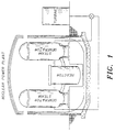
- Nuclear power plants typically contain three major components as shown in Figure 1: a reactor which produces superheated water which is transported to one or more steam generators; and a power turbine, driven by the steam, which generates electrical power.
- the superheated water is transported to the steam generator by a tube sheet.
- the tube sheet in a nuclear steam generator typically forms a pair of tube members or tube rows separated by a lane, and held together by a plurality of support plates, separated at periodic intervals.
- the height of each tube row may exceed 9.8 m (thirty-two feet), and include six to eight or more support plates, each separated horizontally at 0.91-1.83 m (three to six foot) intervals.
- the tube sheets carrying the superheated water are quenched with cool water, which generates the steam which drives the turbine.
- the water exits through a plurality of access ports situated at the bottom of each lane.
- U.S. Patent No. 4,673,027 discloses a device for inspecting and repairing the tubes of a nuclear reactor steam generator.
- the device includes a manipulator which is insertible in the chamber and which may be locked onto the tube sheet for supporting remotely controlled and monitored inspection instruments in tools.
- the manipulator includes a support leg which is adjustable in length in an axial direction, a main arm connected to and movable relative to the support leg and an equipment carrier which is connected to the main arm.
- U. S. Patent No. 4,653,971 discloses a device for selectively positioning a tool carried by a vehicle which moves on a perforated plate, while the device utilizes an elbow which swings a telescoping arm in the position.
- U. S. Patent No. 4,945,979 discloses an improved robotic arm for effecting a tube plugging operation.
- the system also includes an elbow control mechanism.
- U. S. Patent No. 4,205,939 discloses an apparatus for remotely repairing the tubes in a steam generator.
- the device includes a boom pivotally mounted on a column and a system for rotating the column and the boom therewith.
- the disclosed device further includes a tool which is operable on the tubes.
- U. S. Patent No. 4,231,419 discloses a manipulator for inspecting and repairing the tubes of heat exchangers. An inspection arm is inserted and removed through a lead-in nozzle and a swivel arm carries an extendable and retractable mouthpiece carrier with a mouthpiece which can be aligned into the tube openings. Finally, U. S. Patent No. 4,919,194 discloses a method of positioning a robot for inspecting and maintaining operations within a nuclear plant.
- a device for inspecting the support plates and tube sheet of a nuclear steam generator comprising a first boom coupled by a rotatable connector to a second boom, said first and second boom and said rotatable connector being insertable into an access port of a steam generator and into a lane separating two rows of tube members, said rotatable connector being adapted to upright said second boom within said lane, video camera means attached to said second boom for inspecting the tube members and support plates within said lane when said second boom is uprighted characterised in that said second boom comprises a plurality of telescoping members.
- the telescoping members can extend a length of up to approximately 9.8 m (32 feet), the height of a standard steam generator tube.
- the video camera may comprise a CCD video camera.
- the CCD video camera is preferably mounted to a pan and tilt means which is under the control of a remote joy stick.
- the CCD video camera also preferably includes an auto-focus mechanism.
- the present invention includes means for cleaning the tubes and support plates.
- the present invention is also directed to a method for inspecting the support plates and tube sheet of a nuclear steam generator.
- the method comprises the following steps:
- Figure 1 is a representation of the components of a nuclear power plant.
- Figure 2 is a perspective view of the support plate inspection device of the present invention which illustrates the rotatability of the inspection device.
- Figure 3 is a perspective view of the support plate inspection device along line 3-3 Figure 2.
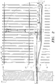
- Figure 4 is an elevated view of the support plate inspection device of the present invention.
- Figure 5 is an isolated view of the telescoping second boom member of the support plate inspection device of the present invention.
- Figure 6 illustrates the tilting ability of the CCD video camera of the support plate inspection device of the present invention.
- Figure 7 illustrates the panning ability of the CCD video camera of the support plate inspection device of the present invention.
- Figure 7A illustrates the attachment of a cleaning means to the support plate inspection device of the present invention.
- the support plate inspection device of the present invention is illustrated. It is to be appreciated by those skilled in the art that the present invention will be utilized to facilitate the easy and rapid inspection of the support plates and tubes of a nuclear steam generator.
- the tubes form rows of tube members 24, 24a which are separated by lanes, and are retained in position by a plurality of support plates 26.
- the bottom of each lane typically includes one or more access ports 18 through which the quenching water exits the generator. This water may have impurities which may corrode or pierce the pipes of the tube sheets, thus resulting in leaks of radioactive superheated water. Such leaks may not be visible to the human eye. Because of the limited access ports, it is difficult for direct human inspection of the pipes to take place.
- the support plate inspection device of the present invention in a preferred embodiment, comprises boom means 14, 16 for extending into an access port 18 of a steam generator and into a lane separating two tube sheet members 24, 24a.
- the boom means is uprightable within the lane.
- a video camera means 30 is attached to the boom means for inspecting the tube members 24, 24a and support plates 26 within the lane when said boom means is uprighted.
- the boom means 14, 16 is multi-sectioned and includes first boom means 14 rotatably coupled to second boom means 16.
- Boom means 14, 16 are joined by a rotatable joint or connector means 20 such as an elbow joint.
- the rotatable connector 20 may be activated mechanically via a hand crank, or by means of a pneumatic or hydraulic activator.
- rotatable connector means 20 facilitates the selective vertical rotation of the second boom means 16 with respect to the first boom means 14 within the lane. While the present invention has been illustrated in the context of a rotatable elbow joint, it is to be appreciated that the present invention may be utilized with any means for rotating or maneuvering the second boom means upwardly relative to first boom means.
- the first and second boom means 14, 16 are, in one embodiment cylindrical booms members, which enter the steam generator through access port 18 in the wall 23 of the steam generator, and extended within the lane separating two rows of tube members 24, 24a.
- Wall 23 is typically constructed from steel.
- the access port 18 may be 2.5 cm, 5 cm, 10 cm or 15 cm (1", 2", 4", or 6") in diameter.
- second boom means 16 preferably comprises a plurality of telescoping members 22 which are extendable pneumatically or hydraulically.
- the multiple telescoping members 22 facilitate the selective vertical or longitudinal adjustment of the second boom means 16 within the tube lane.
- Telescoping members 22 facilitate a full visual inspection of the reactor support plates 26 and tube members 24, 24a.
- the second boom means 16 should have telescoping members 22 of sufficient quantity and length to permit the vertical extension of the second boom means 16 of up to approximately 9.8 m (32 feet). This is the typical height of the tubes and will facilitate inspection of the entire tube sheet and all of the support plates.
- the support plate inspection device 10 further includes a video camera 30 which is attached at or near the distal end of the second telescoping boom means 16, and which transmits video images to a TV monitor located outside of the steam generator.
- the video camera will incorporate CCD (charge-coupled device) technology.
- CCD charge-coupled device
- the advent of CCD (charge-coupled devices) image transducers has permitted television cameras to be fabricated in very small sizes.
- the CCD detector assembly is positioned to receive optical images from the camera lens so that it can convert the components of the received image to corresponding electrical signals. Electrical circuitry associated with the detectors converts the image component signals to standard video signals for use by television receiver/monitors.
- the CCD circuitry may, for example, comprise Sony Model A-7560-026A, which functions to convert optical images received from a lens assembly into electrical video signals.
- the lens assembly of the preferred embodiment may, for example, comprise Sony Model VCL08SBYA.
- pan and tilt means 32 facilitates the horizontal 32a and vertical rotation 32b of the video camera 30.
- the video camera should be able to pan 359° and tilt approximately 180°. In this manner, the video camera 30 can completely inspect the tube members 24, 24a and support plates 26.
- the video camera 30 will also preferably incorporate an auto focus mechanism 34 which, along with the pan and tilt means 32, will be controlled by an operator with a joy stick (not shown) on the outside of the steam generator.
- FIGS 6 and 7 further illustrate connecting cables 36 which facilitate the remote operation of the auto focus and pan and tilt mechanism from the joy stock.
- the cables 36 from the video camera 30 lead to the closed circuit TV monitor located on the outside of the steam generator.
- the present invention further includes means 38 for cleaning the tubes 24, 24a and support plates 26.
- Means 38 will be affixed to the pan and tilt means 32.
- means 38 will comprise a nozzle 40 with attached hose 42 which will jet hot water, steam or a chemical cleaner to clean the tube members 24, 24a and support plates 26.
- the present invention is utilized to inspect the support plates 26 and tube members 24, 24a of a nuclear steam generator.
- the support plate inspection device is inserted through an access port 18 in the wall 23 of the steam generator and through a lane dividing two rows of tube members 24a, 24b.
- the second telescoping member 16 having the CCD video camera 30 attached thereto is uprighted using rotational connector joint means 20.
- the rotational joint means 20 may be uprighted using a mechanical crank, or alternatively, with a hydraulic or pneumatic power source.
- the telescoping second boom means 16 extends upwardly in the lane so as to facilitate the inspection of the support plates and the tube sheet members.
- the telescoping second boom means 16 can be longitudinally adjusted such that the CCD camera 30 can obtain a full and complete visual inspection of the support plates 26 and complete tubes.
- the telescoping members 22 should enable the CCD camera to extend vertically approximately 9.8 m (32 feet) in order facilitate the full examination of the tubes and support plates.
- the CCD camera can fully inspect the tubes 24, 24a sheet and support plates 26.
- the operator safely outside the generator, can monitor the inspection on a closed circuit TV camera used in association with the CCD camera 30 .
- the CCD camera 30 can fully inspect each of the four to six support plates which retain the tube sheet members.
- Means 38 can be utilized to get hot water, steam or chemical cleaner to remove corrosion and dirt from the tube members 24, 24a and support plates 26.
- the telescoping members 22 are retracted and the second boom means is rotated downward as shown in Figure 2.
- the support plate inspection device 10 is withdrawn through access port 18 in wall 23. The procedure may then be repeated by extending the device into another access port 18.
Landscapes
- Physics & Mathematics (AREA)
- Engineering & Computer Science (AREA)
- General Engineering & Computer Science (AREA)
- High Energy & Nuclear Physics (AREA)
- Plasma & Fusion (AREA)
- Mechanical Engineering (AREA)
- Thermal Sciences (AREA)
- Monitoring And Testing Of Nuclear Reactors (AREA)
- Beans For Foods Or Fodder (AREA)
- Investigating Materials By The Use Of Optical Means Adapted For Particular Applications (AREA)
- Paper (AREA)
- Spinning Or Twisting Of Yarns (AREA)
- Analysing Materials By The Use Of Radiation (AREA)
- Mechanical Treatment Of Semiconductor (AREA)
- Cultivation Of Plants (AREA)
Claims (8)
- Vorrichtung zum Inspizieren von Trägerplatten (26) und Rohrwänden eines nuklearen Dampfgenerators, umfassend:einen ersten Ausleger (14), der über ein drehbares Verbindungsstück (20) mit einem zweiten Ausleger gekoppelt ist, wobei der erste und zweite Ausleger (14, 16) und das drehbare Verbindungsstück (20) in eine Zugangsöffnung (18) eines Dampfgenerators und in eine zwei Reihen von Rohrteilen (24, 24a) trennende Gasse einsetzbar ist, wobei das drehbare Verbindungsstück ausgebildet ist, um den zweiten Ausleger (16) in der Gasse aufzustellen;eine Videokameraeinrichtung (30), die an dem zweiten Ausleger (16) zum Inspizieren der Rohrteile (24) und Trägerplatten (26) in der Gasse angebracht ist, wenn der zweite Ausleger aufgerichtet ist, dadurch gekennzeichnet, daß der zweite Ausleger (16) eine Vielzahl von Teleskopelementen (22) umfaßt.
- Vorrichtung nach Anspruch 1, dadurch gekennzeichnet, daß die Videokameraeinrichtung (30) eine CCD-Kamera ist.
- Vorrichtung nach Anspruch 1, weiter umfassend Mittel (38) zum Reinigen der Rohrteile (24) und Trägerplatten (26).
- Vorrichtung nach einem der Ansprüche 1 bis 3, dadurch gekennzeichnet, daß die Rohrteile (24) durch wenigstens eine Trägerplatte (26) getragen werden und das drehbare Verbindungsstück (20) ausgebildet ist, um den zweiten Ausleger (16) in eine Position benachbart zu den Rohrteilen und der wenigstens einen Trägerplatte aufzurichten.
- Vorrichtung nach einem der Ansprüche 2 bis 4, dadurch gekennzeichnet, daß die CCD-Kamera an einem an dem zweiten Ausleger (16) befestigten Dreh- und Schwenkmechanismus (32) befestigt ist.
- Vorrichtung nach Anspruch 5, weiter Mittel zum Steuern des Dreh- und Schwenkmechanismus umfassend.
- Vorrichtung nach einem der Ansprüche 1 bis 6, weiter Mittel zum Ausfahren und Zurückziehen der Teleskopelemente (22) umfassend.
- Verfahren zum Inspizieren der Rohrwand eines Dampfgenerators, umfassend folgende Schritte:Einführen eines ersten und zweiten Auslegers (14, 16), die drehbar miteinander verbunden sind, durch eine Zutrittsöffnung (18) des Dampfgenerators und in eine zwei Reihen von Rohrteilen (24, 24a) trennende Gasse, wobei der zweite Ausleger (16) eine hieran befestigte Kamera (30) besitzt; undAufrichten des zweiten Auslegers (16) in der Gasse,die die Reihen von Rohrteilen (24, 24a) trennt, so daß die Kamera (30) benachbart zu den Rohrteilen (24) und Trägerplatten (26), die durch die Kamera (30) in der Gasse inspiziert werden können, gehalten wird, dadurch gekennzeichnet, daß der zweite Ausleger (16) eine Vielzahl von Teleskopelementen (22) umfaßt.
Applications Claiming Priority (3)
| Application Number | Priority Date | Filing Date | Title |
|---|---|---|---|
| US865118 | 1992-04-08 | ||
| US07/865,118 US5265129A (en) | 1992-04-08 | 1992-04-08 | Support plate inspection device |
| PCT/US1993/003189 WO1993021640A1 (en) | 1992-04-08 | 1993-04-05 | Support plate inspection device |
Publications (3)
| Publication Number | Publication Date |
|---|---|
| EP0635158A1 EP0635158A1 (de) | 1995-01-25 |
| EP0635158A4 EP0635158A4 (de) | 1995-08-16 |
| EP0635158B1 true EP0635158B1 (de) | 1998-10-21 |
Family
ID=25344763
Family Applications (1)
| Application Number | Title | Priority Date | Filing Date |
|---|---|---|---|
| EP93909258A Expired - Lifetime EP0635158B1 (de) | 1992-04-08 | 1993-04-05 | Inspektionsvorrichtung für stützplatte |
Country Status (19)
| Country | Link |
|---|---|
| US (2) | US5265129A (de) |
| EP (1) | EP0635158B1 (de) |
| JP (1) | JP2766075B2 (de) |
| KR (1) | KR950701126A (de) |
| AT (1) | ATE172572T1 (de) |
| AU (1) | AU3973993A (de) |
| BG (1) | BG99162A (de) |
| BR (1) | BR9306214A (de) |
| CA (1) | CA2133822C (de) |
| CZ (1) | CZ247294A3 (de) |
| DE (1) | DE69321714T2 (de) |
| ES (1) | ES2127817T3 (de) |
| GE (1) | GEP19991559B (de) |
| HU (1) | HUT70620A (de) |
| NO (1) | NO943786D0 (de) |
| OA (1) | OA09995A (de) |
| RU (1) | RU94045861A (de) |
| SK (1) | SK121794A3 (de) |
| WO (1) | WO1993021640A1 (de) |
Families Citing this family (43)
| Publication number | Priority date | Publication date | Assignee | Title |
|---|---|---|---|---|
| US6672257B1 (en) * | 1994-05-06 | 2004-01-06 | Foster-Miller, Inc. | Upper bundle steam generator cleaning system and method |
| US5564371A (en) * | 1994-05-06 | 1996-10-15 | Foster Miller, Inc. | Upper bundle steam generator cleaning system and method |
| US5611391A (en) * | 1994-08-04 | 1997-03-18 | Westinghouse Electric Corporation | Powered guide tubes |
| US5575328A (en) * | 1994-08-08 | 1996-11-19 | Westinghouse Electric Corporation | Debris box |
| DE9415987U1 (de) * | 1994-10-05 | 1994-12-22 | Wenzel, Herbert, 76833 Siebeldingen | Abgeschirmter, schwenkbarer Kameramanipulator mit Beleuchtung, zur Inspektion im Kernmantelbereich von Siede- und Druckwasserreaktoren |
| US5615734A (en) * | 1994-11-16 | 1997-04-01 | Westinghouse Electric Corporation | Sludge lance inspection and verification system |
| CA2182509C (en) * | 1994-12-07 | 2001-01-30 | Foster-Miller, Inc. | Deployment system for an upper bundle steam generator cleaning/inspection device |
| US5913320A (en) * | 1995-04-11 | 1999-06-22 | Foster-Miller, Inc. | Sludge removal system |
| WO1997014911A1 (de) * | 1995-10-16 | 1997-04-24 | Siemens Aktiengesellschaft | Verfahren und einrichtung zum einführen eines selbstfahrenden rohrinnenmanipulators in eine rohrleitung |
| US6630947B1 (en) * | 1996-04-10 | 2003-10-07 | The United States Of America As Represented By The Secretary Of The Navy | Method for examining subsurface environments |
| KR100431721B1 (ko) * | 1996-06-14 | 2004-09-13 | 알. 브룩스 어소시에이츠, 인코포레이티드 | 검사장치 |
| FR2751117B1 (fr) * | 1996-07-09 | 1998-11-06 | Framatome Sa | Procede et dispositif d'inspection visuelle de la partie secondaire d'un generateur de vapeur |
| EP1021693A4 (de) | 1996-10-11 | 2002-07-10 | Foster Miller Inc | System zur reinigung, überwachung und reparatur eines dampferzeugers mit höherem rohrbündel |
| US5751610A (en) * | 1996-10-31 | 1998-05-12 | Combustion Engineering, Inc. | On-line robot work-cell calibration |
| DE19709002A1 (de) * | 1997-03-05 | 1998-09-24 | Siemens Ag | Verfahren zur Erzeugung von überbrückten, dotierten Zonen |
| US5895870A (en) * | 1997-05-27 | 1999-04-20 | Framatome Technologies, Inc. | Tube sheet retractable probe |
| US5961277A (en) * | 1997-06-30 | 1999-10-05 | Eskom | Inspection device and method |
| JP2002168992A (ja) * | 2000-11-30 | 2002-06-14 | Hitachi Ltd | 原子炉圧力容器内補修方法及び補修装置 |
| US6530702B2 (en) | 2000-12-02 | 2003-03-11 | Thomas H. S. Harris | Operator supported remote camera positioning and control system |
| KR100450064B1 (ko) * | 2002-04-08 | 2004-09-24 | 한국수력원자력 주식회사 | 증기발생기 전열관내 누적 방사선 피폭량 계측과 전열관내벽의 육안관측을 동시에 수행할 수 있는 소형 ccd카메라 장치 및 이를 이용한 누적 방사선 피폭량 계측방법 |
| US7092477B2 (en) * | 2002-10-01 | 2006-08-15 | Westinghouse Electric Co Llc | BWR inspection manipulator |
| US6923542B2 (en) * | 2003-03-11 | 2005-08-02 | Thomas H. S. Harris | Operator supported remote camera positioning and control system with longeron based beam |
| WO2007011379A2 (en) * | 2004-09-20 | 2007-01-25 | Dominion Engineering Inc. | Improved field transportable high-power ultrasonic transducer assembly |
| KR100855117B1 (ko) | 2006-12-07 | 2008-08-28 | 한전케이피에스 주식회사 | 원자력발전용 증기발생기의 전열관 표면 검사장치 |
| FR2914394B1 (fr) * | 2007-03-28 | 2012-10-26 | Sra Savac | Dispositif d'insertion d'un outillage, notamment d'une sonde a l'interieur d'un generateur de vapeur. |
| FR2915285B1 (fr) * | 2007-04-20 | 2009-06-12 | Sra Savac Sa | Sonde video, destinee a etre inseree entre deux rangees de tubes verticaux d'un echangeur de chaleur |
| US9251921B2 (en) | 2009-05-27 | 2016-02-02 | R. Brooks Associates, Inc. | Steam generator upper bundle inspection tools |
| US8711999B2 (en) * | 2010-03-24 | 2014-04-29 | Areva Inc. | Inspection tool for top guides of a boiling water reactor |
| US8526564B2 (en) | 2010-12-13 | 2013-09-03 | Westinghouse Electric Company Llc | Top guide inspection fixture |
| KR101194576B1 (ko) * | 2010-12-16 | 2012-10-25 | 삼성중공업 주식회사 | 풍력 터빈 조립 및 관리 로봇 및 이를 포함하는 풍력 터빈 시스템 |
| US9146215B2 (en) * | 2011-09-29 | 2015-09-29 | Electric Power Research Institute, Inc. | Apparatus and method for inspection of tubes in a boiler |
| MX362656B (es) | 2012-01-17 | 2019-01-30 | General Electric Technology Gmbh | Montaje de tubos y deflectores en un evaporador horizontal directo. |
| EP2805109B1 (de) | 2012-01-17 | 2019-08-14 | General Electric Technology GmbH | Anlaufsystem für einen horizontalen einmaldurchgangsverdampfer |
| CN104220866A (zh) * | 2012-01-31 | 2014-12-17 | 西门子能量股份有限公司 | 用多轴检测仪自动光学检测工业燃气轮机的和其它发电机械的系统和方法 |
| ES2391678B1 (es) * | 2012-06-01 | 2013-11-07 | Tecnatom, S. A. | Procedimiento de obtención de imágenes calibradas de posición de centros de tubos de un sistema con distribución regular de tubos |
| WO2014031955A1 (en) * | 2012-08-23 | 2014-02-27 | Siemens Energy, Inc. | System and method for optical inspection of off-line industrial gas turbines and other power generation machinery while in turning gear mode |
| KR102285375B1 (ko) * | 2013-05-31 | 2021-08-03 | 뉴스케일 파워, 엘엘씨 | 증기 발생기의 검사 |
| CN104215120A (zh) * | 2013-06-04 | 2014-12-17 | 重庆润蓝水处理工程技术有限公司 | 用于中央空调末端表冷器的自动清洗装置 |
| CN104749183B (zh) * | 2013-12-30 | 2017-07-14 | 中核武汉核电运行技术股份有限公司 | 一种蒸汽发生器二次侧管板视频检查工具 |
| HUE039732T2 (hu) * | 2014-12-23 | 2019-01-28 | Cms Costruzione Macch Speciali S R L | Horizontális csõtágítógép |
| US10871256B2 (en) * | 2015-07-27 | 2020-12-22 | Schlumberger Technology Corporation | Property enhancement of surfaces by electrolytic micro arc oxidation |
| US10811150B2 (en) * | 2016-08-16 | 2020-10-20 | Ge-Hitachi Nuclear Energy Americas Llc | Remotely operated vehicles, systems, and methods for inspecting core shrouds |
| US11326844B2 (en) * | 2019-04-18 | 2022-05-10 | Amerapex NDT LLC | Heat exchanger integrated services |
Citations (1)
| Publication number | Priority date | Publication date | Assignee | Title |
|---|---|---|---|---|
| US4231419A (en) * | 1978-07-21 | 1980-11-04 | Kraftwerk Union Aktiengesellschaft | Manipulator for inspection and possible repair of the tubes of heat exchangers, especially of steam generators for nuclear reactors |
Family Cites Families (79)
| Publication number | Priority date | Publication date | Assignee | Title |
|---|---|---|---|---|
| US1971486A (en) * | 1933-02-18 | 1934-08-28 | Paramount Productions Inc | Tilt and panning head for motion picture camera tripods |
| US2165512A (en) * | 1938-03-30 | 1939-07-11 | Ralph M Schofield | Camera periscope |
| US2293207A (en) * | 1939-08-25 | 1942-08-18 | Warner Bros | Apparatus for panning and/or tilting motion picture apparatus |
| US2700523A (en) * | 1953-02-10 | 1955-01-25 | Ned C Pollard | Panhead for cameras |
| US2703691A (en) * | 1954-06-15 | 1955-03-08 | Luther W Minnis | Camera support |
| NL106535C (de) * | 1957-01-09 | |||
| US2957365A (en) * | 1958-06-04 | 1960-10-25 | Sachtler Wendelin | Camera panning heads |
| US3114799A (en) * | 1958-10-30 | 1963-12-17 | Pye Ltd | Television cameras |
| GB879529A (en) * | 1959-02-19 | 1961-10-11 | Thompson Nuclear Energy Co Ltd | Improvements relating to remote inspection equipment |
| US3103257A (en) * | 1961-04-11 | 1963-09-10 | Richards Philip | Elevating apparatus |
| US3164838A (en) * | 1961-09-28 | 1965-01-05 | Ervin L Heinrich | Panning and tilting mount for a camera |
| US3399614A (en) * | 1965-06-15 | 1968-09-03 | George J. Fischer | Remotely controlled mounts |
| US3437753A (en) * | 1965-12-07 | 1969-04-08 | Coburn Mfg Co Inc | Pan and tilt television camera |
| US3636778A (en) * | 1970-06-05 | 1972-01-25 | Atomic Energy Commission | Method and means for dimensional inspection of tubing |
| US3780571A (en) * | 1971-04-22 | 1973-12-25 | Programmed & Remote Syst Corp | Reactor vessel inspection device |
| GB1372327A (en) * | 1971-10-11 | 1974-10-30 | Commissariat Energie Atomique | Articulated manipulator |
| US3926040A (en) * | 1973-09-04 | 1975-12-16 | Rockwell International Corp | Device for guiding sensor movement within a tube |
| FR2267612B1 (de) * | 1974-04-10 | 1978-08-04 | Commissariat Energie Atomique | |
| JPS5157489A (en) * | 1974-11-15 | 1976-05-19 | Mitsubishi Heavy Ind Ltd | Jidokensasochino kontorooruhoho |
| US3952982A (en) * | 1975-01-07 | 1976-04-27 | Lewis David P | All angle camera mount with vernier adjustment |
| US4018345A (en) * | 1975-11-18 | 1977-04-19 | Combustion Engineering, Inc. | Surface traversing apparatus |
| US4205939A (en) * | 1978-01-30 | 1980-06-03 | Westinghouse Electric Corp. | Apparatus for remotely repairing tubes in a steam generator |
| US4213732A (en) * | 1978-04-13 | 1980-07-22 | Westinghouse Electric Corp. | Apparatus for remotely repairing tubes in a steam generator |
| US4222540A (en) * | 1978-12-01 | 1980-09-16 | Westinghouse Electric Corp. | Tube sheet pan and tilt camera platform |
| GB2048496B (en) * | 1979-02-28 | 1983-09-07 | British Gas Corp | Pipe inspection apparatus |
| GB2043248B (en) * | 1979-02-28 | 1983-04-27 | British Gas Corp | Ultrasonic pipe inspection apparatus |
| US4325026A (en) * | 1979-03-19 | 1982-04-13 | Westinghouse Electric Corp. | Plural coil eddy current mapping probe |
| FR2455834A1 (fr) * | 1979-03-30 | 1980-11-28 | Framatome Sa | Dispositif d'inspection televisuelle de la surface interieure d'une enceinte cylindrique |
| FR2471026A1 (fr) * | 1979-11-30 | 1981-06-12 | Intercontrole Sa | Appareil porte-sonde pour le controle des tubes d'un generateur de vapeur |
| US4344146A (en) * | 1980-05-08 | 1982-08-10 | Chesebrough-Pond's Inc. | Video inspection system |
| DE3020093A1 (de) * | 1980-05-27 | 1981-12-03 | Hochtemperatur-Reaktorbau GmbH, 5000 Köln | Fernsehkamera fuer die besichtigung von innenraeumen bei kernreaktoranlagen |
| DE3029811A1 (de) * | 1980-08-06 | 1982-02-18 | Kraftwerk Union AG, 4330 Mülheim | Manipulator zur fernbedienbaren inspektion und gegebenenfalls reparatur von waermtauscherrohren |
| DE3122660C2 (de) * | 1981-06-06 | 1986-06-19 | Brown Boveri Reaktor GmbH, 6800 Mannheim | Einrichtung zur Inspektion und/oder zur Reparatur der Rohre eines Dampferzeugers einer Kernkraftanlage |
| US4341452A (en) * | 1981-08-10 | 1982-07-27 | Torkel Korling | Triaxial universal camera mount |
| JPS5845494U (ja) * | 1981-09-21 | 1983-03-26 | 川添 道雄 | 雲台 |
| US4432931A (en) * | 1981-10-02 | 1984-02-21 | Electric Power Research Institute, Inc. | Inspection system |
| US4429329A (en) * | 1981-11-09 | 1984-01-31 | Electric Power Research Institute, Inc. | Remote visual inspection system |
| DE3202248A1 (de) * | 1982-01-25 | 1983-08-04 | Kraftwerk Union AG, 4330 Mülheim | Rohrgassen-manipulator, spritzkopf und zugehoeriges spritzverfahren zum hochdruck-abschlaemmen von waermetauschern |
| US4474439A (en) * | 1982-01-26 | 1984-10-02 | Brown Garrett W | Camera support |
| DE3202883C2 (de) * | 1982-01-29 | 1986-09-18 | Kraftwerk Union AG, 4330 Mülheim | Bewegungseinrichtung zum Antrieb einer Sonde |
| EP0086341B1 (de) * | 1982-01-29 | 1985-08-28 | Kraftwerk Union Aktiengesellschaft | Sonde zur zerstörungsfreien Prüfung von zylindrischen Hohlräumen, insbesondere von Dampferzeugerrohren |
| US4613476A (en) * | 1982-05-10 | 1986-09-23 | Jacobson Earl Bruce | Radiation attenuating fluid work environment |
| FR2527308A1 (fr) * | 1982-05-19 | 1983-11-25 | Intercontrole Sa | Dispositif pour l'introduction d'un mobile de positionnement d'un organe sur une plaque tubulaire |
| FR2530214A1 (fr) * | 1982-07-15 | 1984-01-20 | Commissariat Energie Atomique | Vehicule autopropulse a bras articules, reservoir et dispositif d'entrainement debrayable pouvant etre montes sur ledit vehicule |
| JPS59112241U (ja) * | 1983-01-18 | 1984-07-28 | ミノルタ株式会社 | カメラ支持装置 |
| FR2544540B1 (fr) * | 1983-04-13 | 1985-10-25 | Commissariat Energie Atomique | Machine d'examen d'un assemblage combustible de reacteur nucleaire |
| US4575185A (en) * | 1983-08-01 | 1986-03-11 | Combustion Engineering, Inc. | System for a fiber optic cable for remote inspection of internal structure of a nuclear steam generator |
| US4764334A (en) * | 1983-10-17 | 1988-08-16 | Westinghouse Electric Corp. | Visual inspection system for radioactive fuel assemblies using fiberoptics |
| US4638667A (en) * | 1984-01-20 | 1987-01-27 | Westinghouse Electric Corp. | Remote probe positioning apparatus |
| US4661309A (en) * | 1984-02-13 | 1987-04-28 | Combustion Engineering, Inc. | Equipment transporter for nuclear steam generator |
| FR2566309B1 (fr) * | 1984-06-22 | 1986-11-07 | Barras Provence | Dispositif pour positionner selectivement un outil porte par un vehicule se deplacant sur la plaque perforee d'un faisceau de tubes |
| US4581938A (en) * | 1984-07-30 | 1986-04-15 | Combustion Engineering, Inc. | Tool for scanning the inner surface of a large pipe |
| GB8503148D0 (en) * | 1985-02-07 | 1985-04-17 | Nat Nuclear Corp Ltd | Visual inspection systems |
| US4752127A (en) * | 1985-03-13 | 1988-06-21 | Westinghouse Electric Corp. | Optical tube inspection apparatus |
| US4672741A (en) * | 1985-06-27 | 1987-06-16 | Westinghouse Electric Corp. | End effector apparatus for positioning a steam generator heat exchanger tube plugging tool |
| US4757258A (en) * | 1985-11-27 | 1988-07-12 | Westinghouse Electric Corp. | Probe carrier system for inspecting boiler tubes |
| US4760876A (en) * | 1986-09-02 | 1988-08-02 | Westinghouse Electric Corp. | Remote inspection device transport system |
| US4655567A (en) * | 1986-03-07 | 1987-04-07 | Morley John D | Remotely manipulatable panning and tilting mount for video cameras and the like and method of manipulating a camera |
| FR2596859B1 (fr) * | 1986-04-07 | 1988-07-15 | Framatome Sa | Dispositif de mesure a distance du diametre exterieur d'un element de forme cylindrique saillant par rapport a la surface d'une plaque |
| US4673268A (en) * | 1986-05-12 | 1987-06-16 | Wheeler Ernest E | Pan and tilt mount |
| JPS6353492A (ja) * | 1986-08-25 | 1988-03-07 | 株式会社東芝 | 制御棒駆動機構 |
| GB8622879D0 (en) * | 1986-09-23 | 1986-10-29 | Dsam Ltd | Camera support systems |
| USD303120S (en) | 1986-12-29 | 1989-08-29 | Otto Nemenz International | Tilt plate assembly for photographic and television cameras |
| USD303269S (en) | 1987-01-09 | 1989-09-05 | Heiwa Seiki Kogyo Kabushiki Kaisha | Tripod pan head and handle |
| FR2610137B1 (fr) * | 1987-01-28 | 1993-09-24 | Electricite De France | Systeme de decontamination des tuyauteries primaires et de la boite a eau d'un generateur de vapeur de centrale nucleaire |
| US5065703A (en) * | 1987-03-18 | 1991-11-19 | Electric Power Research Institute, Inc. | Flexible lance for steam generator secondary side sludge removal |
| US4846573A (en) * | 1987-04-10 | 1989-07-11 | Identechs Corporation | Shape memory effect alloy pull wire articulator for borescopes |
| DE8712772U1 (de) * | 1987-09-22 | 1989-01-19 | Siemens AG, 1000 Berlin und 8000 München | Gerät zur Inspektion und/oder Reparatur von Wärmetauscherrohren |
| FR2625936A1 (fr) * | 1988-01-14 | 1989-07-21 | Hispano Suiza Sa | Procede de mise en place d'un robot porte-outils destine a des interventions en milieu humainement hostile |
| US4856354A (en) * | 1988-03-07 | 1989-08-15 | Combustion Engineering, Inc. | Inspection probe manipulator |
| FR2631697B1 (fr) * | 1988-05-17 | 1991-07-26 | Hispano Suiza Sa | Appareil pour le controle optique du profil interne d'un tube ou d'un alesage |
| US4855838A (en) * | 1988-05-27 | 1989-08-08 | Cues, Inc. | Remotely controlled pan and tilt television camera |
| US4945979A (en) * | 1988-06-23 | 1990-08-07 | Westinghouse Electric Corp. | Robotic arm for delivering a tube plugging tool |
| US4890713A (en) * | 1988-07-22 | 1990-01-02 | Pagano Raymond V | Pan and tilt motor for surveillance camera |
| FR2644568B1 (fr) * | 1989-03-16 | 1991-07-05 | Intercontrole Sa | Dispositif d'intervention, notamment pour le controle, l'inspection et la maintenance des echangeurs de chaleur |
| US4963903A (en) * | 1989-10-25 | 1990-10-16 | Cane Richard M | Camera positioning system |
| US5069172A (en) * | 1990-09-26 | 1991-12-03 | Westinghouse Electric Corp. | Nuclear steam generator sludge lance method and apparatus |
| DE9017888U1 (de) * | 1990-10-02 | 1992-09-24 | Panther GmbH Herstellung, Vertrieb und Verleih filmtechnischer Geräte, 8024 Oberhaching | Kamerakran |
| US10048127B2 (en) | 2015-08-05 | 2018-08-14 | Viavi Solutions Inc. | Optical filter and spectrometer |
-
1992
- 1992-04-08 US US07/865,118 patent/US5265129A/en not_active Expired - Lifetime
-
1993
- 1993-04-05 CA CA002133822A patent/CA2133822C/en not_active Expired - Lifetime
- 1993-04-05 SK SK1217-94A patent/SK121794A3/sk unknown
- 1993-04-05 AT AT93909258T patent/ATE172572T1/de not_active IP Right Cessation
- 1993-04-05 WO PCT/US1993/003189 patent/WO1993021640A1/en not_active Ceased
- 1993-04-05 EP EP93909258A patent/EP0635158B1/de not_active Expired - Lifetime
- 1993-04-05 ES ES93909258T patent/ES2127817T3/es not_active Expired - Lifetime
- 1993-04-05 BR BR9306214A patent/BR9306214A/pt not_active Application Discontinuation
- 1993-04-05 DE DE69321714T patent/DE69321714T2/de not_active Expired - Lifetime
- 1993-04-05 JP JP5518418A patent/JP2766075B2/ja not_active Expired - Lifetime
- 1993-04-05 CZ CZ942472A patent/CZ247294A3/cs unknown
- 1993-04-05 GE GEAP19932668A patent/GEP19991559B/en unknown
- 1993-04-05 RU RU94045861/25A patent/RU94045861A/ru unknown
- 1993-04-05 HU HU9402856A patent/HUT70620A/hu unknown
- 1993-04-05 AU AU39739/93A patent/AU3973993A/en not_active Abandoned
- 1993-11-19 US US08/154,960 patent/US5504788A/en not_active Expired - Fee Related
-
1994
- 1994-10-05 OA OA60567A patent/OA09995A/en unknown
- 1994-10-07 KR KR1019940703544A patent/KR950701126A/ko active Granted
- 1994-10-07 NO NO943786A patent/NO943786D0/no unknown
- 1994-11-04 BG BG99162A patent/BG99162A/xx unknown
Patent Citations (1)
| Publication number | Priority date | Publication date | Assignee | Title |
|---|---|---|---|---|
| US4231419A (en) * | 1978-07-21 | 1980-11-04 | Kraftwerk Union Aktiengesellschaft | Manipulator for inspection and possible repair of the tubes of heat exchangers, especially of steam generators for nuclear reactors |
Also Published As
| Publication number | Publication date |
|---|---|
| CZ247294A3 (en) | 1995-03-15 |
| JPH07508585A (ja) | 1995-09-21 |
| NO943786L (no) | 1994-10-07 |
| GEP19991559B (en) | 1999-03-05 |
| SK121794A3 (en) | 1995-07-11 |
| AU3973993A (en) | 1993-11-18 |
| ES2127817T3 (es) | 1999-05-01 |
| EP0635158A1 (de) | 1995-01-25 |
| WO1993021640A1 (en) | 1993-10-28 |
| ATE172572T1 (de) | 1998-11-15 |
| DE69321714D1 (de) | 1998-11-26 |
| CA2133822C (en) | 2001-06-19 |
| NO943786D0 (no) | 1994-10-07 |
| JP2766075B2 (ja) | 1998-06-18 |
| BG99162A (en) | 1995-08-28 |
| US5504788A (en) | 1996-04-02 |
| BR9306214A (pt) | 1998-06-23 |
| DE69321714T2 (de) | 1999-06-10 |
| HUT70620A (en) | 1995-10-30 |
| CA2133822A1 (en) | 1993-10-28 |
| KR950701126A (ko) | 1995-02-20 |
| RU94045861A (ru) | 1997-01-27 |
| OA09995A (en) | 1996-03-29 |
| KR100369724B1 (de) | 2003-03-28 |
| EP0635158A4 (de) | 1995-08-16 |
| US5265129A (en) | 1993-11-23 |
Similar Documents
| Publication | Publication Date | Title |
|---|---|---|
| US5265129A (en) | Support plate inspection device | |
| US5305356A (en) | Inspection device | |
| JP3219745B2 (ja) | 蒸気発生器の上側チューブ束のクリーニング装置および方法 | |
| KR101086344B1 (ko) | 증기발생기 2차측 관판 상부의 전열관 다발 틈새 육안 검사 및 이물질 제거장치 | |
| EP0112576B1 (de) | Ultraschall-Dekontaminationsroboter | |
| US6672257B1 (en) | Upper bundle steam generator cleaning system and method | |
| CA2257681C (en) | Inspection device | |
| EP1361001A2 (de) | Verfahren und Anordnung zur Untersuchung von Abwasserrohrleitungen | |
| EP0743884B1 (de) | Einsatzsystem einer reinigungs-/inspektionseinrichtung für die oberen rohrbündel eines dampferzeugers | |
| US5615734A (en) | Sludge lance inspection and verification system | |
| JP3250811B2 (ja) | 蒸気発生器の上側チューブ束のクリーニング・検査・補修のための装置 | |
| KR100982393B1 (ko) | 증기발생기 수실 내부의 원격 육안검사 시스템 | |
| Mahil et al. | Remote InSpection and Maintenance Activities in the CANDU Nuclear Plants | |
| KR102575698B1 (ko) | 증기발생기의 이물질 제거 장치 및 이를 이용한 증기발생기의 이물질 제거 방법 | |
| Patenaude | Ultrasonic decontamination robot | |
| Seeberger | Remote controlled in-pipe manipulators for milling, welding and EC-testing, for application in BWRS |
Legal Events
| Date | Code | Title | Description |
|---|---|---|---|
| PUAI | Public reference made under article 153(3) epc to a published international application that has entered the european phase |
Free format text: ORIGINAL CODE: 0009012 |
|
| 17P | Request for examination filed |
Effective date: 19941014 |
|
| AK | Designated contracting states |
Kind code of ref document: A1 Designated state(s): AT BE CH DE DK ES FR GB GR IE IT LI LU MC NL PT SE |
|
| A4 | Supplementary search report drawn up and despatched | ||
| AK | Designated contracting states |
Kind code of ref document: A4 Designated state(s): AT BE CH DE DK ES FR GB GR IE IT LI LU MC NL PT SE |
|
| 17Q | First examination report despatched |
Effective date: 19960314 |
|
| GRAG | Despatch of communication of intention to grant |
Free format text: ORIGINAL CODE: EPIDOS AGRA |
|
| GRAG | Despatch of communication of intention to grant |
Free format text: ORIGINAL CODE: EPIDOS AGRA |
|
| GRAH | Despatch of communication of intention to grant a patent |
Free format text: ORIGINAL CODE: EPIDOS IGRA |
|
| GRAH | Despatch of communication of intention to grant a patent |
Free format text: ORIGINAL CODE: EPIDOS IGRA |
|
| GRAA | (expected) grant |
Free format text: ORIGINAL CODE: 0009210 |
|
| AK | Designated contracting states |
Kind code of ref document: B1 Designated state(s): AT BE CH DE DK ES FR GB GR IE IT LI LU MC NL PT SE |
|
| PG25 | Lapsed in a contracting state [announced via postgrant information from national office to epo] |
Ref country code: NL Free format text: LAPSE BECAUSE OF FAILURE TO SUBMIT A TRANSLATION OF THE DESCRIPTION OR TO PAY THE FEE WITHIN THE PRESCRIBED TIME-LIMIT Effective date: 19981021 Ref country code: LI Free format text: LAPSE BECAUSE OF FAILURE TO SUBMIT A TRANSLATION OF THE DESCRIPTION OR TO PAY THE FEE WITHIN THE PRESCRIBED TIME-LIMIT Effective date: 19981021 Ref country code: IT Free format text: LAPSE BECAUSE OF FAILURE TO SUBMIT A TRANSLATION OF THE DESCRIPTION OR TO PAY THE FEE WITHIN THE PRESCRIBED TIME-LIMIT;WARNING: LAPSES OF ITALIAN PATENTS WITH EFFECTIVE DATE BEFORE 2007 MAY HAVE OCCURRED AT ANY TIME BEFORE 2007. THE CORRECT EFFECTIVE DATE MAY BE DIFFERENT FROM THE ONE RECORDED. Effective date: 19981021 Ref country code: GR Free format text: LAPSE BECAUSE OF NON-PAYMENT OF DUE FEES Effective date: 19981021 Ref country code: CH Free format text: LAPSE BECAUSE OF FAILURE TO SUBMIT A TRANSLATION OF THE DESCRIPTION OR TO PAY THE FEE WITHIN THE PRESCRIBED TIME-LIMIT Effective date: 19981021 Ref country code: AT Free format text: LAPSE BECAUSE OF FAILURE TO SUBMIT A TRANSLATION OF THE DESCRIPTION OR TO PAY THE FEE WITHIN THE PRESCRIBED TIME-LIMIT Effective date: 19981021 |
|
| REF | Corresponds to: |
Ref document number: 172572 Country of ref document: AT Date of ref document: 19981115 Kind code of ref document: T |
|
| REG | Reference to a national code |
Ref country code: CH Ref legal event code: EP |
|
| REF | Corresponds to: |
Ref document number: 69321714 Country of ref document: DE Date of ref document: 19981126 |
|
| REG | Reference to a national code |
Ref country code: IE Ref legal event code: FG4D |
|
| PG25 | Lapsed in a contracting state [announced via postgrant information from national office to epo] |
Ref country code: PT Free format text: LAPSE BECAUSE OF FAILURE TO SUBMIT A TRANSLATION OF THE DESCRIPTION OR TO PAY THE FEE WITHIN THE PRESCRIBED TIME-LIMIT Effective date: 19990121 Ref country code: DK Free format text: LAPSE BECAUSE OF FAILURE TO SUBMIT A TRANSLATION OF THE DESCRIPTION OR TO PAY THE FEE WITHIN THE PRESCRIBED TIME-LIMIT Effective date: 19990121 |
|
| ET | Fr: translation filed | ||
| NLV1 | Nl: lapsed or annulled due to failure to fulfill the requirements of art. 29p and 29m of the patents act | ||
| PG25 | Lapsed in a contracting state [announced via postgrant information from national office to epo] |
Ref country code: LU Free format text: LAPSE BECAUSE OF NON-PAYMENT OF DUE FEES Effective date: 19990405 Ref country code: IE Free format text: LAPSE BECAUSE OF NON-PAYMENT OF DUE FEES Effective date: 19990405 |
|
| REG | Reference to a national code |
Ref country code: CH Ref legal event code: PL |
|
| REG | Reference to a national code |
Ref country code: ES Ref legal event code: FG2A Ref document number: 2127817 Country of ref document: ES Kind code of ref document: T3 |
|
| PLBE | No opposition filed within time limit |
Free format text: ORIGINAL CODE: 0009261 |
|
| STAA | Information on the status of an ep patent application or granted ep patent |
Free format text: STATUS: NO OPPOSITION FILED WITHIN TIME LIMIT |
|
| 26N | No opposition filed | ||
| PG25 | Lapsed in a contracting state [announced via postgrant information from national office to epo] |
Ref country code: MC Free format text: LAPSE BECAUSE OF NON-PAYMENT OF DUE FEES Effective date: 19991031 |
|
| REG | Reference to a national code |
Ref country code: IE Ref legal event code: MM4A |
|
| REG | Reference to a national code |
Ref country code: GB Ref legal event code: IF02 |
|
| PGFP | Annual fee paid to national office [announced via postgrant information from national office to epo] |
Ref country code: DE Payment date: 20120419 Year of fee payment: 20 Ref country code: BE Payment date: 20120412 Year of fee payment: 20 |
|
| PGFP | Annual fee paid to national office [announced via postgrant information from national office to epo] |
Ref country code: GB Payment date: 20120404 Year of fee payment: 20 Ref country code: SE Payment date: 20120411 Year of fee payment: 20 Ref country code: FR Payment date: 20120504 Year of fee payment: 20 |
|
| PGFP | Annual fee paid to national office [announced via postgrant information from national office to epo] |
Ref country code: ES Payment date: 20120510 Year of fee payment: 20 |
|
| REG | Reference to a national code |
Ref country code: DE Ref legal event code: R071 Ref document number: 69321714 Country of ref document: DE |
|
| REG | Reference to a national code |
Ref country code: GB Ref legal event code: PE20 Expiry date: 20130404 |
|
| BE20 | Be: patent expired |
Owner name: R. *BROOKS ASSOCIATES INC. Effective date: 20130405 |
|
| PG25 | Lapsed in a contracting state [announced via postgrant information from national office to epo] |
Ref country code: GB Free format text: LAPSE BECAUSE OF EXPIRATION OF PROTECTION Effective date: 20130404 Ref country code: DE Free format text: LAPSE BECAUSE OF EXPIRATION OF PROTECTION Effective date: 20130406 |
|
| REG | Reference to a national code |
Ref country code: ES Ref legal event code: FD2A Effective date: 20130801 |
|
| PG25 | Lapsed in a contracting state [announced via postgrant information from national office to epo] |
Ref country code: ES Free format text: LAPSE BECAUSE OF EXPIRATION OF PROTECTION Effective date: 20130406 |