EP0635197A2 - Appareil et procédé pour l'emballage et le montage d'une tondeuse à fil - Google Patents
Appareil et procédé pour l'emballage et le montage d'une tondeuse à fil Download PDFInfo
- Publication number
- EP0635197A2 EP0635197A2 EP94250186A EP94250186A EP0635197A2 EP 0635197 A2 EP0635197 A2 EP 0635197A2 EP 94250186 A EP94250186 A EP 94250186A EP 94250186 A EP94250186 A EP 94250186A EP 0635197 A2 EP0635197 A2 EP 0635197A2
- Authority
- EP
- European Patent Office
- Prior art keywords
- tube
- housing
- trimmer
- neck
- handle
- Prior art date
- Legal status (The legal status is an assumption and is not a legal conclusion. Google has not performed a legal analysis and makes no representation as to the accuracy of the status listed.)
- Withdrawn
Links
Images



Classifications
-
- B—PERFORMING OPERATIONS; TRANSPORTING
- B25—HAND TOOLS; PORTABLE POWER-DRIVEN TOOLS; MANIPULATORS
- B25G—HANDLES FOR HAND IMPLEMENTS
- B25G1/00—Handle constructions
- B25G1/04—Handle constructions telescopic; extensible; sectional
-
- A—HUMAN NECESSITIES
- A01—AGRICULTURE; FORESTRY; ANIMAL HUSBANDRY; HUNTING; TRAPPING; FISHING
- A01D—HARVESTING; MOWING
- A01D34/00—Mowers; Mowing apparatus of harvesters
- A01D34/01—Mowers; Mowing apparatus of harvesters characterised by features relating to the type of cutting apparatus
- A01D34/412—Mowers; Mowing apparatus of harvesters characterised by features relating to the type of cutting apparatus having rotating cutters
- A01D34/416—Flexible line cutters
-
- A—HUMAN NECESSITIES
- A01—AGRICULTURE; FORESTRY; ANIMAL HUSBANDRY; HUNTING; TRAPPING; FISHING
- A01D—HARVESTING; MOWING
- A01D34/00—Mowers; Mowing apparatus of harvesters
- A01D34/835—Mowers; Mowing apparatus of harvesters specially adapted for particular purposes
- A01D34/90—Mowers; Mowing apparatus of harvesters specially adapted for particular purposes for carrying by the operator
-
- B—PERFORMING OPERATIONS; TRANSPORTING
- B25—HAND TOOLS; PORTABLE POWER-DRIVEN TOOLS; MANIPULATORS
- B25F—COMBINATION OR MULTI-PURPOSE TOOLS NOT OTHERWISE PROVIDED FOR; DETAILS OR COMPONENTS OF PORTABLE POWER-DRIVEN TOOLS NOT PARTICULARLY RELATED TO THE OPERATIONS PERFORMED AND NOT OTHERWISE PROVIDED FOR
- B25F5/00—Details or components of portable power-driven tools not particularly related to the operations performed and not otherwise provided for
- B25F5/02—Construction of casings, bodies or handles
Definitions
- the invention relates to assembling flexible line trimmers shipped in a disassembled state.
- An electrically powered trimmer includes a cutting element mounted to the drive shaft of an electric motor, a housing in which the motor is mounted and that is attached to one end of a tube, and a pair of handles at the opposite end of the tube.
- the cutting element is most often a length of flexible line, though it could also be a blade.
- the length of line extends from a line head connected to the shaft of the motor. The head is spun rapidly to flail the line against vegetation. Because the line frequently breaks, a supply of flexible line is stored on a spool in the head, the end of the line extending through an opening in the head.
- An operator holds the trimmer while standing erect by grasping with one hand a main handle attached to the end the tube that extends upwardly and rearwardly from the housing.
- a main handle attached to the end the tube that extends upwardly and rearwardly from the housing.
- the other hand may grasp an auxiliary handle that can be attached lower down on the tube between the main handle and the housing to provide enhanced control.
- a trigger located, usually, on the main handle operates a normally off switch that turns the motor on and off.
- power is delivered to the motor by a 120 volt alternating current from a household outlet.
- a plug or "pigtail" for connection to an extension cord running from the outlet is typically located in the rear of the handle, but is sometimes located elsewhere on the trimmer.
- the power source alternately is a battery pack placed in the vicinity of the main handle for balance. With either power source, a power wire runs to the electric motor in the housing through the tube to the normally-off trigger switch on the rear handle.
- the tube that supports the handles is manufactured in two or more sections that are separated and folded over when placed in a box. In other cases, the tube may be manufactured as a single piece but not attached to the motor housing, the main handle or both to save space.
- the trimmer For safety, the trimmer must be "prewired," as the wire through the tube carries relatively high voltage (120 volt) alternating current.
- the wire is run through the tube and attached to the electric motor and the power plug and/or trigger switch on the main handle before packaging and shipment.
- the lower length of the tube is then attached to the housing and the upper length is attached to the rear handle.
- the trimmer When the trimmer is taken from the box, the two pieces of the tube are pushed together and secured with bolts.
- One end of the tube length has a smaller diameter so that it slides into the larger diameter end of the other tube length.
- Retailers would, naturally, prefer to provide to customers the convenience of a fully assembled trimmer. To maintain the goodwill of their customers, some retailers are willing to assemble the trimmers when they are offered for sale or are sold. However, this may require extra trained personnel. Sometimes they do not have the personnel immediately available or must charge a fee to recover costs, thus inconveniencing the customer.
- Beihoffer addresses the problem of the extra length of wire and teaches cutting notches in the ends of the tubes so that the length of the wire may be reduced. However, he provides only a partial solution. Assembly of the tube sections is still required and is inconvenient to the consumer. Thus, the demand for a solution remains.
- the invention is an electric trimmer which can be pulled from a package in a knocked-down state and properly assembled in seconds without tools or the opportunity for missteps.
- consumers may conveniently assemble the line trimmer, without hassle and without the help of, or the expense to, retailers.
- a prewired electric trimmer is packaged for shipment with a single elongated handle support inserted into and received by a specially adapted extended neck of a housing for an electric motor.
- the tubular handle support is pulled from the housing by a main handle located at the end of the handle support. Once the handle support is extended, it is secured so that the trimmer has convenient height to operate while standing.
- the handle support and the housing cooperate to maintain proper orientation of the main handle with respect to the housing.
- the invention thus eliminates the inconvenience, and problems associated with assembling two pieces of the tubular handle support, as well as the possibility of improper orientation. Furthermore, the wire running from the main handle to the electric motor does not interfere with final assembly.
- the neck of the housing includes a straight guide, parallel to the handle, and a cooperating member that maintains proper orientation of the tube.
- the cooperating member is preferably a spring biased detent button that clicks into place when the tube is extended to an operating position, the clicking providing feedback to the consumer that the tube is properly extended.
- the guide includes a ramp with an abrupt end that slowly depresses the detent button as the tube is extending and then drops the button at its end, locking the tube into place and giving the customer further assurance that the tube is properly extended and in place.
- Arrows or other visual indicators may also be placed on the tube to indicate to the customer when the tube has been properly extended and placed in an operating position.
- FIGURE 1 is a side elevational view of a fully assembled line trimmer.
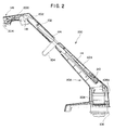
- FIGURE 2 is a side elevational view of the line trimmer of Fig. 1 in a collapsed shipping position and with a side of the handle and the motor and handle support tube housing removed.
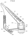
- FIGURE 3 is a side elevational view of the line trimmer of Fig. 1 in an alternate collapsed shipping position.
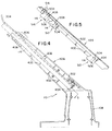
- FIGURE 4 is side view of one half of a motor and handle tube housing for the line trimmer of Fig. 1 with the handle tube in a collapsed shipping position.
- FIGURE 5 is a partial cross-section of the motor and handle support tube housing half of Fig. 4, taken along section line 5-5, with the handle tube shown partly in section at three locations: at a fully collapsed, shipping position; a midway position; and a fully-assembled position.
- FIGURE 6A is a cross section taken through the motor and handle support tube housing of the line trimmer of Fig. 1, taken along the section line 6A-6A in Fig. 1.
- FIGURE 6B is a cross section taken through the housing of the line trimmer of Fig. 1, taken along the section line 6B-6B in Fig. 1.
- FIGURE 6C is a cross section taken through the housing of the line trimmer of Fig. 1, taken along the section line 6C-6C in Fig. 1.
- FIGURE 6D is a cross section taken through the housing of the line trimmer of Fig. 1, taken along the section line 6D-6D in Fig. 1.
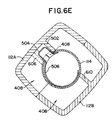
- FIGURE 6E is a cross section taken through the motor and handle tube housing of the line trimmer of Fig. 1, taken along the section line 6E-6E in Fig. 1.
- FIGURE 7 is a simplified side elevational view of half of the motor and handle support tube housing of the line trimmer of Fig. 1.
- FIGURE 6 is a partial cross-section of the housing half of Fig. 7 taken along section line 8-8.
- FIGURE 9A is a partial cross-section of an alternate embodiment of the housing half of Fig. 7 taken along section line 8-8 in Fig. 7.
- FIGURE 9B is a partial cross-section of an alternate embodiment for the housing half of Fig. 7 taken along section line 8-8 in Fig. 7.
- FIGURE 1 Illustrated in FIGURE 1 is a fully-assembled flexible line trimmer 100 oriented in a trimming position. While standing, an operator grasps main handle 102 and auxiliary handle 104 to maneuver a rotating head 106 in close proximity to the ground. Head 106, having a conventional design, holds a spool of flexible cutting line for supplying a length of cutting line (not shown) that is flailed against ground vegetation by the rapidly spun head. The head is spun by an alternating current electric motor that is mounted within portion 108 of an integrally formed motor and handle tube housing 110. Neck 112 of the motor and handle tube housing extends upwardly and rearwardly, generally an angle to the ground plane and toward the operator. Connected to neck 112 is a lower end of a handle support tube 114.
- Main handle 102 is connected to an opposite, top end of the tube 114, in a conventional manner.
- the position of the main handle is fixed, but it may be telescoping or rotating if desired.
- Auxiliary handle 104 is clamped to the tube in a conventional manner.
- Power is supplied to the line trimmer by connecting an extension cord from a 120 volt wall socket to a male plug (not seen) mounted within at a distal end 116 of main handle 102.
- the male plug is coupled through a normally closed switch, operated by trigger 118, to the motor by a wire (not shown) that runs through the tube 114 to the motor and handle tube housing 110.
- Pulling trigger 118 supplies current to the motor through the wire, causing the head 106 to rotate at high speeds.
- a battery can be incorporated with the main handle to supply power to a D.C. electric motor in the power housing.
- trimmers may be operated or controlled effectively with only one hand, permitting the auxiliary handle to be dispensed with.
- FIGURE 2 when a line trimmer is packaged for shipping, it is placed in a knocked-down or collapsed condition, with the handle support tube 114 retracted within neck 112 of housing 110. In this fully retracted position, handle support tube 114 is received substantially within neck 112 of motor and handle support tube housing 110. Only enough of the tube remains for connecting handles 102 and 104. Please note that the drawing shows only side pieces 102A and 110A of, respectively, the main handle and the housing. Complementary side pieces are joined to make the handle 102 and housing 110.
- wire 202 is run through tube 114 and connected at one end to plug 204 and switch 206 and to motor 208 at the other end.
- the wire is also pinned to the handle 102 and to neck 112 of housing 110 by wrapping it around several closely spaced tabs or bosses that pinch the cord when pulled. Pinning helps to prevent loosening the electrical connections with the plug and switch or with the motor.
- the handle is then attached to the end of the tube for shipment.
- An extra length of wire 202 is pinned within housing 112, along the side of the end of the tube 114 when it is fully retracted to take up slack on the extra length of wire that is required to accommodate full extension of the tube. Pinning the extra length of wire in this manner helps to prevent interference from the wire kinking or jamming between the tube and housing when being withdrawn and to ensure placement of the tube and wire in the proper locations during assembly to avoid crimping and other problems that may occur during assembly and shipment. The pinning also accommodates retracting the tube subsequently, if desired.
- Wire loop 302 is much shorter than wire loop 210 in Fig. 2.
- Shipping insert 306 prevents the end of tube 114 from chafing wire 202 during shipping. Note that the end of tube 114 is specially adapted to the handle so that the handle fits over and locks on the tube in a fixed, predetermined orientation with the tube.
- FIGURE 4 the drawing is a simplified illustration of housing half 110. No motor or head is shown. Tube 114 is held in position within neck 112 of the housing by a series of spaced-apart reenforcing ribs 402 that are curved to receive the circular tube.
- the housing also includes an end stop 404 for tube 114. When tube 114 is in a fully extended position and the trimmer is being held in the operative position, ribs 406 at the end of neck 112 of the housing 110 are more closely spaced to support housing 110 on tube 114 and to distribute stress.
- the trough functions as a guide for a detent button 504 that extends through a hole through the wall of the tube near its end, within housing 110.
- Detent button 504 is biased to an extended position with spring 506. After the trimmer is unpackaged, a person pulls on the main handle 102 (Fig. 1) on the end of the tube extending from the housing 110. Detent button rides up the trough and maintains a fixed and proper orientation of the tube with respect to the housing.
- Ramp 508 is formed in the middle of the trough so that the detent button is slowly depressed as the tube is extended.
- the drawing illustrates position 510 of the detent button when the tube is fully retracted; as it is being extended, which is position 512; and at position 514 where it is fully extended.
- the abrupt end of the ramp prevents the detent button from riding down the trough once extended, thus locking the tube 114 in a fully extended position.
- the clicking motion and sound the detent button makes when falling at the end of the ramp also provides important reassurance to a customer that the tube is fully extended and secured. Having the trimmer locked into a full extended position removes all decisions from the consumer.
- Knob 516 turns on a screw extending through both halves of housing 110 to tighten the neck of the housing about the tube. The trimmer is then finally assembled.
- no release is shown, it is possible to install a release mechanism to depress the detent button so that the tube may be collapsed for storage, transport or adjustability.
- the abrupt end may be replaced with a relatively steep ramp that provides the clicking action upon extension but will depress the detent button when sufficient force is applied to the tube to collapse it.
- the detent button rests in a second, semi-circular guide formed at the end of the ramp by wall 408 (which is also shown in Fig. 4) and the next adjacent of the plurality of ribs 406.
- This semicircular guide allows the tube 114 to be rotated one hundred eighty degrees so that the axis of rotation of the head 106 (Fig. 1) is parallel to the ground, allowing the trimmer to be used to cut an edge.
- FIGURES 6A-6D are cross-sections taken through neck 112 of housing 110, as indicated on Fig. 1, at each of the ribs 402.
- Handle support tube 114 rests within the circular area 602 between the curved edges of ribs 402.
- Ramp 508 is located in the center of the guide.
- Tube 114 may be rotated one hundred eighty degrees by loosening the clamping of the end of neck 112 around the tube, its rotation being limited by the detent button 504 hitting walls 502 and 610.
- housing half 112A is shown by itself, without tube 114 obstructing a view of trough 604, ramp 508 within the trough, and second guide 604.
- FIGURES 9A and 9B which are cross sections of housing half 110A taken along section line 8-8 in Fig. 7, illustrate alternate profiles for ramp 508.
- the ramp is replaced with a series of knolls 902 that have slopes in each direction over which the detent button 504 (Fig.S) rides when moving in either the retracting or extending directions along the trough 604 (Fig. 7).
- the handle support tube 114 (Fig. 5) is thus movable between the fully extended and fully retracted positions and thus may be collapsed once fully extended. Valleys between the knolls provide incremental or discrete positioning of the detent button 504 (Fig. 5) and feedback to the customer that proper extension of the tube has been accomplished.
- the height of handle 102 (Fig.
Landscapes
- Engineering & Computer Science (AREA)
- Mechanical Engineering (AREA)
- Life Sciences & Earth Sciences (AREA)
- Environmental Sciences (AREA)
- Harvester Elements (AREA)
Applications Claiming Priority (2)
| Application Number | Priority Date | Filing Date | Title |
|---|---|---|---|
| US96483 | 1993-07-22 | ||
| US08/096,483 US5446964A (en) | 1993-07-22 | 1993-07-22 | Apparatus and method for packaging and assembling a flexible line trimmer |
Publications (2)
| Publication Number | Publication Date |
|---|---|
| EP0635197A2 true EP0635197A2 (fr) | 1995-01-25 |
| EP0635197A3 EP0635197A3 (fr) | 1996-03-06 |
Family
ID=22257543
Family Applications (1)
| Application Number | Title | Priority Date | Filing Date |
|---|---|---|---|
| EP94250186A Withdrawn EP0635197A3 (fr) | 1993-07-22 | 1994-07-22 | Appareil et procédé pour l'emballage et le montage d'une tondeuse à fil. |
Country Status (5)
| Country | Link |
|---|---|
| US (2) | US5446964A (fr) |
| EP (1) | EP0635197A3 (fr) |
| JP (1) | JPH07308113A (fr) |
| AU (1) | AU6759594A (fr) |
| CA (1) | CA2128594A1 (fr) |
Cited By (7)
| Publication number | Priority date | Publication date | Assignee | Title |
|---|---|---|---|---|
| EP0657255A1 (fr) * | 1993-12-10 | 1995-06-14 | Black & Decker Inc. | Outil actionné par l'énergie électrique |
| EP0703044A1 (fr) * | 1994-09-02 | 1996-03-27 | Goblin Limited | Assemblage flexible |
| EP0707924A3 (fr) * | 1994-10-20 | 1997-06-11 | Black & Decker Inc | Tondeuse à fil de coupe munie d'une manche rabattable |
| USD509715S1 (en) | 2003-03-28 | 2005-09-20 | Black & Decker Inc. | Cordless string trimmer |
| CN102870552A (zh) * | 2011-07-14 | 2013-01-16 | 百得有限公司 | 电气装置 |
| CN104798527A (zh) * | 2014-01-28 | 2015-07-29 | 苏州宝时得电动工具有限公司 | 割草机 |
| CN105052356A (zh) * | 2015-07-30 | 2015-11-18 | 宁波大叶园林设备有限公司 | 把三工位六工步合并为一的低排放汽油割灌机组装方法 |
Families Citing this family (20)
| Publication number | Priority date | Publication date | Assignee | Title |
|---|---|---|---|---|
| US5594990A (en) * | 1993-07-22 | 1997-01-21 | Wci Outdoor Products, Inc. | Lawn trimming and edging apparatus having motor housing rotatable on extendable handle |
| US5933966A (en) * | 1997-07-23 | 1999-08-10 | Mcculloch Corporation | Shaft telescoping and rotational adjustment mechanism for a lawn and garden tool |
| JP2904767B1 (ja) * | 1998-03-13 | 1999-06-14 | 大成工材株式会社 | フレキシブルシャフトライナーアッセンブリ及び回転伝達シャフト |
| IT248273Y1 (it) * | 1999-08-27 | 2002-12-16 | Eurosystems S P A | Motozappa portatile. |
| USD450226S1 (en) | 2000-02-03 | 2001-11-13 | The Toro Company | Vegetation trimmer |
| US6439088B1 (en) | 2000-04-25 | 2002-08-27 | The Toro Company | Reconfigurable vegetation trimmer and method of use |
| EP1210858B1 (fr) | 2000-11-29 | 2006-12-20 | Black & Decker Inc. | Protecteur de plantes |
| EP1210859A1 (fr) | 2000-11-29 | 2002-06-05 | Black & Decker Inc. | Protecteur de plantes |
| USD510512S1 (en) | 2004-03-24 | 2005-10-11 | Black & Decker Inc. | String trimmer |
| US20090025351A1 (en) * | 2007-07-26 | 2009-01-29 | Harry T. Faeldan | Tri-wheeled modular housing telescopic grass trimmer |
| WO2013032373A1 (fr) * | 2011-08-26 | 2013-03-07 | Husqvarna Ab | Outil de coupe portatif alimenté par batterie |
| JP6066285B2 (ja) * | 2012-12-19 | 2017-01-25 | 株式会社マキタ | 刈払機 |
| JP5955759B2 (ja) * | 2012-12-19 | 2016-07-20 | 株式会社マキタ | 刈払機 |
| US9472992B2 (en) * | 2013-07-11 | 2016-10-18 | The Toro Company | Electric motor support structure and power equipment unit incorporating same |
| US10314228B2 (en) * | 2014-05-16 | 2019-06-11 | Positec Power Tools (Suzhou) Co., Ltd. | Grass trimmer and cord delivering method of grass trimmer |
| DE102016106557A1 (de) * | 2016-04-11 | 2017-10-12 | Festool Gmbh | Hand-Werkzeugmaschine mit einem Antriebsmotor |
| US10688647B2 (en) * | 2017-05-19 | 2020-06-23 | The Toro Company | Lawn and garden tool with boom having adjustable length and detachable boom sections |
| US10875201B2 (en) | 2018-04-04 | 2020-12-29 | Swanstrom Tools Usa Inc. | Relief guard for hand tools |
| US11369057B2 (en) * | 2019-11-04 | 2022-06-28 | Black & Decker, Inc. | String trimmer with pole break |
| EP3824714B1 (fr) | 2019-11-19 | 2022-10-19 | Andreas Stihl AG & Co. KG | Appareil d'usinage pourvu de partie tubulaire et de dispositif câble ainsi que procédé de montage |
Family Cites Families (36)
| Publication number | Priority date | Publication date | Assignee | Title |
|---|---|---|---|---|
| US942490A (en) * | 1908-12-04 | 1909-12-07 | William John Dunn | Telescopic article. |
| US2641012A (en) * | 1948-02-12 | 1953-06-09 | Fred O Storrs | Telescopic brush handle |
| US2756555A (en) * | 1953-12-24 | 1956-07-31 | Dale W Lewis | Lawn edger and hedge trimmer |
| US2863328A (en) * | 1955-06-09 | 1958-12-09 | Toro Mfg Corp Of Minnesota | Guiding and control structure for powered ground traversing implements |
| US3330102A (en) * | 1965-03-26 | 1967-07-11 | Black & Decker Mfg Co | Pivoted index latch for lawn trimmer-edger |
| US3561199A (en) * | 1969-07-17 | 1971-02-09 | Murphy Ind Inc G W | System for converting edger-trimmer device |
| US4052789A (en) * | 1976-12-02 | 1977-10-11 | Weed Eater, Inc. | Rotary cutting assembly |
| US3831278A (en) * | 1972-08-03 | 1974-08-27 | Dynamics Corp America | Grass trimmer |
| US3861127A (en) * | 1972-10-11 | 1975-01-21 | Sunbeam Corp | Housing for a portable grass shear |
| US3803819A (en) * | 1972-11-28 | 1974-04-16 | Black & Decker Mfg Co | Trimmer-edger with handle clamp |
| US3879573A (en) * | 1973-12-05 | 1975-04-22 | Black & Decker Mfg Co | Electrical device handle and protector therefor |
| US4043101A (en) * | 1974-01-21 | 1977-08-23 | Rockwell International Corporation | Edger-trimmer head indexing mechanism |
| DE2520873A1 (de) * | 1975-05-10 | 1976-11-18 | Langenstein Feld Garten | Rasenkantenschneider |
| US4156967A (en) * | 1976-12-02 | 1979-06-05 | Weed Eater, Inc. | Rotary cutting assembly |
| USD251699S (en) | 1977-08-05 | 1979-05-01 | Averitt Marnie C | Weed cutting apparatus |
| US4238866A (en) * | 1979-08-14 | 1980-12-16 | Taylor Nelson D | Rain gutter cleaning device |
| US4338719A (en) * | 1980-08-08 | 1982-07-13 | Black & Decker Inc. | Filament type vegetation trimmer |
| US4463498A (en) * | 1982-08-31 | 1984-08-07 | Everts Robert G | Coupling for flailing line trimmer handles |
| US4550499A (en) * | 1983-07-18 | 1985-11-05 | Mcculloch Corporation | String trimmer with cut line retention pocket |
| GB8330228D0 (en) * | 1983-11-11 | 1983-12-21 | Black & Decker Inc | Vegetation cutters |
| US4603478A (en) * | 1984-08-13 | 1986-08-05 | Allegretti & Company | Trimmer with adjustable handle |
| US4654971A (en) * | 1985-09-13 | 1987-04-07 | Hudd Enterprises | Prunner with collapsible drive shaft and housing |
| US4641431A (en) * | 1985-11-18 | 1987-02-10 | Leming Anthony D | Hedge trimmer |
| USD301009S (en) | 1986-11-28 | 1989-05-09 | Allegretti & Company | String trimmer |
| US4860451A (en) * | 1986-11-28 | 1989-08-29 | Allegretti & Company | String trimmer |
| US4760646A (en) * | 1987-01-09 | 1988-08-02 | Frederick Siegler | Tree pruner and hedge trimmer |
| GB8714817D0 (en) * | 1987-06-24 | 1987-07-29 | Flymo Ltd | Grass trimmer |
| US4829675A (en) * | 1987-08-19 | 1989-05-16 | The Toro Company | Electrical appliance and handle for same |
| JPH0531867Y2 (fr) * | 1988-03-23 | 1993-08-17 | ||
| USD308003S (en) | 1988-05-18 | 1990-05-22 | Roy Kraynyk | Electric trimmer motor housing with an extendable handle |
| US4924573A (en) * | 1989-03-15 | 1990-05-15 | Huddleston Earl M | Pruner with power driven extension |
| US4916818A (en) * | 1989-03-27 | 1990-04-17 | Panek Gregory E | Long reach tree trimmer |
| US4976031A (en) * | 1989-06-01 | 1990-12-11 | Ron Miller | Telescopic hedge trimming apparatus |
| US5114006A (en) * | 1990-04-05 | 1992-05-19 | Wilk Peter J | Tool assembly |
| US5305882A (en) * | 1991-12-10 | 1994-04-26 | Kaplan Alan F | Self-storing collapsible implement |
| US5301491A (en) * | 1992-02-14 | 1994-04-12 | Sam Moore Furniture Industries, Inc. | Method of packaging a chair for shipment |
-
1993
- 1993-07-22 US US08/096,483 patent/US5446964A/en not_active Expired - Lifetime
-
1994
- 1994-07-21 AU AU67595/94A patent/AU6759594A/en not_active Abandoned
- 1994-07-21 CA CA002128594A patent/CA2128594A1/fr not_active Abandoned
- 1994-07-22 JP JP6201266A patent/JPH07308113A/ja active Pending
- 1994-07-22 EP EP94250186A patent/EP0635197A3/fr not_active Withdrawn
-
1995
- 1995-06-07 US US08/477,645 patent/US5634322A/en not_active Expired - Lifetime
Cited By (9)
| Publication number | Priority date | Publication date | Assignee | Title |
|---|---|---|---|---|
| EP0657255A1 (fr) * | 1993-12-10 | 1995-06-14 | Black & Decker Inc. | Outil actionné par l'énergie électrique |
| EP0703044A1 (fr) * | 1994-09-02 | 1996-03-27 | Goblin Limited | Assemblage flexible |
| EP0707924A3 (fr) * | 1994-10-20 | 1997-06-11 | Black & Decker Inc | Tondeuse à fil de coupe munie d'une manche rabattable |
| EP1249317A3 (fr) * | 1994-10-20 | 2003-03-05 | Black & Decker Inc. | Tondeuse à fil de coupe munie d'un manche rabattable |
| EP1527672A3 (fr) * | 1994-10-20 | 2005-07-27 | BLACK & DECKER INC. | Tondeuse à fil de coupe munie d'un manche rabattable |
| USD509715S1 (en) | 2003-03-28 | 2005-09-20 | Black & Decker Inc. | Cordless string trimmer |
| CN102870552A (zh) * | 2011-07-14 | 2013-01-16 | 百得有限公司 | 电气装置 |
| CN104798527A (zh) * | 2014-01-28 | 2015-07-29 | 苏州宝时得电动工具有限公司 | 割草机 |
| CN105052356A (zh) * | 2015-07-30 | 2015-11-18 | 宁波大叶园林设备有限公司 | 把三工位六工步合并为一的低排放汽油割灌机组装方法 |
Also Published As
| Publication number | Publication date |
|---|---|
| CA2128594A1 (fr) | 1995-01-23 |
| AU6759594A (en) | 1995-02-02 |
| US5446964A (en) | 1995-09-05 |
| JPH07308113A (ja) | 1995-11-28 |
| US5634322A (en) | 1997-06-03 |
| EP0635197A3 (fr) | 1996-03-06 |
Similar Documents
| Publication | Publication Date | Title |
|---|---|---|
| US5446964A (en) | Apparatus and method for packaging and assembling a flexible line trimmer | |
| US5594990A (en) | Lawn trimming and edging apparatus having motor housing rotatable on extendable handle | |
| US6701623B2 (en) | Collapsable transverse handle for elongated tool | |
| US7882642B2 (en) | Trimmer head for use in flexible line rotary trimmers having improved line loading mechanism | |
| US8707567B2 (en) | Trimmer head for use in flexible line rotary trimmers having improved line loading mechanism | |
| US4951890A (en) | Drill-operated adapter for unwinding fishing line from reels | |
| US4282954A (en) | Rewinder device | |
| US6142405A (en) | Extension cord storage and dispensing system | |
| US8001694B2 (en) | Fixed line rotary head trimmer with quick friction rotational lock for string trimmer machine | |
| US10130030B2 (en) | Trimmer head | |
| US5771582A (en) | Apparatus for carrying spare line spool on flexible line trimmer | |
| US8251212B2 (en) | Small hand carried barrel-shaped case for the storage and dispensing of spools of electrical wire | |
| US6513791B1 (en) | Fish tape with automatic reeling feature | |
| CN107148839A (zh) | 用于线式修剪机机头的缠绕机构 | |
| US6779749B2 (en) | Cord take-up reel for electric powered lawn mower | |
| CN102804534A (zh) | 带有电缆卷盘器的可移动电装置 | |
| WO2023278755A1 (fr) | Ensemble coupe-bordure et tête de coupe-bordure destinée à être utilisée avec celui-ci | |
| WO2009135169A1 (fr) | Appareil coupe-herbe | |
| US5573422A (en) | Electrical cord retaining and protection system | |
| US6176729B1 (en) | Cord-to-cord restraining device | |
| US20070272905A1 (en) | Ergonomic Center Handle Fish Tape | |
| US20050072645A1 (en) | Cord reel with electrical outlets | |
| EP1676803B1 (fr) | Dévidoir mobile de tuyau pliant | |
| KR20190131742A (ko) | 케이블 정리용 나선형 밴드 랩핑 장치 | |
| JP2700118B2 (ja) | バンド結束機 |
Legal Events
| Date | Code | Title | Description |
|---|---|---|---|
| PUAI | Public reference made under article 153(3) epc to a published international application that has entered the european phase |
Free format text: ORIGINAL CODE: 0009012 |
|
| AK | Designated contracting states |
Kind code of ref document: A2 Designated state(s): DE FR GB IT |
|
| PUAL | Search report despatched |
Free format text: ORIGINAL CODE: 0009013 |
|
| AK | Designated contracting states |
Kind code of ref document: A3 Designated state(s): DE FR GB IT |
|
| 17P | Request for examination filed |
Effective date: 19960514 |
|
| GRAG | Despatch of communication of intention to grant |
Free format text: ORIGINAL CODE: EPIDOS AGRA |
|
| 17Q | First examination report despatched |
Effective date: 19981110 |
|
| GRAG | Despatch of communication of intention to grant |
Free format text: ORIGINAL CODE: EPIDOS AGRA |
|
| GRAH | Despatch of communication of intention to grant a patent |
Free format text: ORIGINAL CODE: EPIDOS IGRA |
|
| STAA | Information on the status of an ep patent application or granted ep patent |
Free format text: STATUS: THE APPLICATION IS DEEMED TO BE WITHDRAWN |
|
| 18D | Application deemed to be withdrawn |
Effective date: 19991225 |