EP0635247B1 - Ellbogenlifter - Google Patents
Ellbogenlifter Download PDFInfo
- Publication number
- EP0635247B1 EP0635247B1 EP94105939A EP94105939A EP0635247B1 EP 0635247 B1 EP0635247 B1 EP 0635247B1 EP 94105939 A EP94105939 A EP 94105939A EP 94105939 A EP94105939 A EP 94105939A EP 0635247 B1 EP0635247 B1 EP 0635247B1
- Authority
- EP
- European Patent Office
- Prior art keywords
- elbow
- forearm
- lifter according
- mating part
- arm
- Prior art date
- Legal status (The legal status is an assumption and is not a legal conclusion. Google has not performed a legal analysis and makes no representation as to the accuracy of the status listed.)
- Expired - Lifetime
Links
Images


Classifications
-
- A—HUMAN NECESSITIES
- A61—MEDICAL OR VETERINARY SCIENCE; HYGIENE
- A61F—FILTERS IMPLANTABLE INTO BLOOD VESSELS; PROSTHESES; DEVICES PROVIDING PATENCY TO, OR PREVENTING COLLAPSING OF, TUBULAR STRUCTURES OF THE BODY, e.g. STENTS; ORTHOPAEDIC, NURSING OR CONTRACEPTIVE DEVICES; FOMENTATION; TREATMENT OR PROTECTION OF EYES OR EARS; BANDAGES, DRESSINGS OR ABSORBENT PADS; FIRST-AID KITS
- A61F2/00—Filters implantable into blood vessels; Prostheses, i.e. artificial substitutes or replacements for parts of the body; Appliances for connecting them with the body; Devices providing patency to, or preventing collapsing of, tubular structures of the body, e.g. stents
- A61F2/50—Prostheses not implantable in the body
- A61F2/54—Artificial arms or hands or parts thereof
- A61F2/58—Elbows; Wrists ; Other joints; Hands
- A61F2/582—Elbow joints
-
- A—HUMAN NECESSITIES
- A61—MEDICAL OR VETERINARY SCIENCE; HYGIENE
- A61F—FILTERS IMPLANTABLE INTO BLOOD VESSELS; PROSTHESES; DEVICES PROVIDING PATENCY TO, OR PREVENTING COLLAPSING OF, TUBULAR STRUCTURES OF THE BODY, e.g. STENTS; ORTHOPAEDIC, NURSING OR CONTRACEPTIVE DEVICES; FOMENTATION; TREATMENT OR PROTECTION OF EYES OR EARS; BANDAGES, DRESSINGS OR ABSORBENT PADS; FIRST-AID KITS
- A61F2/00—Filters implantable into blood vessels; Prostheses, i.e. artificial substitutes or replacements for parts of the body; Appliances for connecting them with the body; Devices providing patency to, or preventing collapsing of, tubular structures of the body, e.g. stents
- A61F2/50—Prostheses not implantable in the body
- A61F2/68—Operating or control means
-
- A—HUMAN NECESSITIES
- A61—MEDICAL OR VETERINARY SCIENCE; HYGIENE
- A61F—FILTERS IMPLANTABLE INTO BLOOD VESSELS; PROSTHESES; DEVICES PROVIDING PATENCY TO, OR PREVENTING COLLAPSING OF, TUBULAR STRUCTURES OF THE BODY, e.g. STENTS; ORTHOPAEDIC, NURSING OR CONTRACEPTIVE DEVICES; FOMENTATION; TREATMENT OR PROTECTION OF EYES OR EARS; BANDAGES, DRESSINGS OR ABSORBENT PADS; FIRST-AID KITS
- A61F2/00—Filters implantable into blood vessels; Prostheses, i.e. artificial substitutes or replacements for parts of the body; Appliances for connecting them with the body; Devices providing patency to, or preventing collapsing of, tubular structures of the body, e.g. stents
- A61F2/50—Prostheses not implantable in the body
- A61F2/76—Means for assembling, fitting or testing prostheses, e.g. for measuring or balancing, e.g. alignment means
-
- A—HUMAN NECESSITIES
- A61—MEDICAL OR VETERINARY SCIENCE; HYGIENE
- A61F—FILTERS IMPLANTABLE INTO BLOOD VESSELS; PROSTHESES; DEVICES PROVIDING PATENCY TO, OR PREVENTING COLLAPSING OF, TUBULAR STRUCTURES OF THE BODY, e.g. STENTS; ORTHOPAEDIC, NURSING OR CONTRACEPTIVE DEVICES; FOMENTATION; TREATMENT OR PROTECTION OF EYES OR EARS; BANDAGES, DRESSINGS OR ABSORBENT PADS; FIRST-AID KITS
- A61F2/00—Filters implantable into blood vessels; Prostheses, i.e. artificial substitutes or replacements for parts of the body; Appliances for connecting them with the body; Devices providing patency to, or preventing collapsing of, tubular structures of the body, e.g. stents
- A61F2/50—Prostheses not implantable in the body
- A61F2/68—Operating or control means
- A61F2/70—Operating or control means electrical
-
- A—HUMAN NECESSITIES
- A61—MEDICAL OR VETERINARY SCIENCE; HYGIENE
- A61F—FILTERS IMPLANTABLE INTO BLOOD VESSELS; PROSTHESES; DEVICES PROVIDING PATENCY TO, OR PREVENTING COLLAPSING OF, TUBULAR STRUCTURES OF THE BODY, e.g. STENTS; ORTHOPAEDIC, NURSING OR CONTRACEPTIVE DEVICES; FOMENTATION; TREATMENT OR PROTECTION OF EYES OR EARS; BANDAGES, DRESSINGS OR ABSORBENT PADS; FIRST-AID KITS
- A61F2/00—Filters implantable into blood vessels; Prostheses, i.e. artificial substitutes or replacements for parts of the body; Appliances for connecting them with the body; Devices providing patency to, or preventing collapsing of, tubular structures of the body, e.g. stents
- A61F2/50—Prostheses not implantable in the body
- A61F2002/5007—Prostheses not implantable in the body having elastic means different from springs, e.g. including an elastomeric insert
-
- A—HUMAN NECESSITIES
- A61—MEDICAL OR VETERINARY SCIENCE; HYGIENE
- A61F—FILTERS IMPLANTABLE INTO BLOOD VESSELS; PROSTHESES; DEVICES PROVIDING PATENCY TO, OR PREVENTING COLLAPSING OF, TUBULAR STRUCTURES OF THE BODY, e.g. STENTS; ORTHOPAEDIC, NURSING OR CONTRACEPTIVE DEVICES; FOMENTATION; TREATMENT OR PROTECTION OF EYES OR EARS; BANDAGES, DRESSINGS OR ABSORBENT PADS; FIRST-AID KITS
- A61F2/00—Filters implantable into blood vessels; Prostheses, i.e. artificial substitutes or replacements for parts of the body; Appliances for connecting them with the body; Devices providing patency to, or preventing collapsing of, tubular structures of the body, e.g. stents
- A61F2/50—Prostheses not implantable in the body
- A61F2002/5072—Prostheses not implantable in the body having spring elements
-
- A—HUMAN NECESSITIES
- A61—MEDICAL OR VETERINARY SCIENCE; HYGIENE
- A61F—FILTERS IMPLANTABLE INTO BLOOD VESSELS; PROSTHESES; DEVICES PROVIDING PATENCY TO, OR PREVENTING COLLAPSING OF, TUBULAR STRUCTURES OF THE BODY, e.g. STENTS; ORTHOPAEDIC, NURSING OR CONTRACEPTIVE DEVICES; FOMENTATION; TREATMENT OR PROTECTION OF EYES OR EARS; BANDAGES, DRESSINGS OR ABSORBENT PADS; FIRST-AID KITS
- A61F2/00—Filters implantable into blood vessels; Prostheses, i.e. artificial substitutes or replacements for parts of the body; Appliances for connecting them with the body; Devices providing patency to, or preventing collapsing of, tubular structures of the body, e.g. stents
- A61F2/50—Prostheses not implantable in the body
- A61F2002/5072—Prostheses not implantable in the body having spring elements
- A61F2002/5078—2-D spiral springs
-
- A—HUMAN NECESSITIES
- A61—MEDICAL OR VETERINARY SCIENCE; HYGIENE
- A61F—FILTERS IMPLANTABLE INTO BLOOD VESSELS; PROSTHESES; DEVICES PROVIDING PATENCY TO, OR PREVENTING COLLAPSING OF, TUBULAR STRUCTURES OF THE BODY, e.g. STENTS; ORTHOPAEDIC, NURSING OR CONTRACEPTIVE DEVICES; FOMENTATION; TREATMENT OR PROTECTION OF EYES OR EARS; BANDAGES, DRESSINGS OR ABSORBENT PADS; FIRST-AID KITS
- A61F2/00—Filters implantable into blood vessels; Prostheses, i.e. artificial substitutes or replacements for parts of the body; Appliances for connecting them with the body; Devices providing patency to, or preventing collapsing of, tubular structures of the body, e.g. stents
- A61F2/50—Prostheses not implantable in the body
- A61F2/68—Operating or control means
- A61F2002/6854—Operating or control means for locking or unlocking a joint
Definitions
- the invention relates to a method for applying a Torque on the elbow axis of an upper arm prosthesis Swiveling the forearm with the help of a spring force.
- the invention further relates to an elbow lifter for an arm prosthesis, whose upper arm fitting part over at least one elbow axis is articulated to a forearm fitting part, the pivoting thereof supported by a spring element of the elbow lifter becomes.
- US-A-2,626,398 discloses an elbow lifter which is designed as in the elastic elbow axis integrated, tensionable spring element is that concentrically overlapping the elbow axis Hollow shaft acted on with the forearm fitting part Rails is rotatably connected.
- One is also planned manually operated cantilever phase. Otherwise, however, this shows Elbow lifters also have the disadvantages mentioned above on.
- the invention is therefore based on the object of a method and to develop an elbow lifter with which the Let the aforementioned shortcomings be avoided.
- This task is based on the method described above solved according to the invention in that the torque curve depending on the flexion angle of the forearm essentially is parabolic and its lowest values in the Stretch position of essentially 5 ° to 25 °, preferably 10 ° to 20 ° and at maximum diffraction and its maximum at about 90 ° having.
- the stated task is based on the one described at the beginning Elbow lifter solved according to the invention by a gear, its input directly from the spring element with a tensile force or is acted upon indirectly, and its output on the inner End of one with an inner and an outer end Geborgangs attacks, the outer end of one with the Elbow axis a fixed point defining the torque lever Upper arm fitting part can be determined, the power transmission through the transmission takes place so that the course of the at the fixed point of the Upper arm fitting attacking torque depending on Diffraction angle of the forearm fitting part is essentially parabolic is and its lowest values in the stretched position of essentially 5 ° to 25 °, preferably 10 ° to 20 ° and at maximum Diffraction and has its maximum at about 90 °.
- a torque curve is achieved according to the invention, of the exact needs of the support corresponds to the flexion of the forearm. It can be if the system is correctly adjusted, the swing phase of the upper arm stump for advancing and lowering the forearm. This can even be used to control the Forearm required pull rope is eliminated, making a larger one The amputee's freedom of movement is made possible.
- the spring force by an electrical adjustment depending on the bending angle and the torque curve changed and / or by an electrically applied, additional torque is amplified.
- Device-wise can it be advantageous if the adjustment of the spring element is over a first motor controlled by a sensor takes place.
- an additional torque on the forearm fitting applying motor is provided.
- the spring element is preferably a spiral spring, but could also a tension spring or a similar storage element be.
- the arm prosthesis shown in Figure 1 includes an upper arm fitting 1 and a forearm fitting part 2, which has an elbow axis 3 are hinged together.
- an elbow lifter 4 is provided for support the pivoting of the forearm fitting part 2 into different flexion positions. This points a housing that accommodates or encloses all of its components 5 on that in an adapted recess in the forearm fitting 2 is inserted.
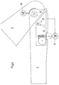
- the elbow lifter 4 shown in Figure 2 essentially comprises a coil spring 6, a cam gear 7, a the force from the spiral spring 6 on the cam mechanism 7 transmitting, designed as a flexible elastic belt 8 Power transmission element and a cam gear 7 kinematic connecting element with the upper arm fitting part 1 9.
- the cam gear 7 comprises two cams 7a and 7b, each of which is non-rotatably seated on a common shaft 10.
- the spiral spring 6 is fastened in a spring housing 11 and acts as a rotational force on a driven pulley 12 which an axis 13 sits.
- the bias of the coil spring 6 can corresponding to the to be compensated, attacking the forearm fitting part 2 Weight can be changed by twisting a worm wheel 14, one for actuating it from the outside accessible, manually operated turntable 15, a knurled wheel or the like is provided.
- the belt 8 is at one end at a fixed point 16 attached to the driven pulley 12, wraps around almost completely the outer curve contour of the first cam 7a and is with its other end on the outer circumference of this first cam 7a attached via a fixed point 17, the transmission input of the cam mechanism 7 defined.
- the flexible tension member 9 is at its inner end to the transmission output defining fixed point 18 on the circumference of the second cam 7b attached, is then mounted around a housing 5 Deflection roller 19 guided and is with its outer, from the Housing 5 led out at one end with the elbow axis 3 a fixed point 20 defining the torque arm of the upper arm fitting part 1 set.
- Figure 2 shows that the Tension element 9 with the forearm fitting part 2 extended, the outer curve contour the second cam 7b only over a short Section wraps around and in the area between the pulley 19 and the fixed point 20 on the upper arm fitting part 1 on its lower, contour 21 is approximately circular segment-shaped.
- Figure 3 shows the forearm fitting part 2 in its maximum flexion angle.
- a comparison with Figure 2 makes it clear that starting from the extended arm position with increasing flexion angle of the forearm fitting part 2 with respect to the upper arm fitting part 1 of the straps 8 off the first cam 7a and on that of the Coil spring 6 driven driven pulley 12 wound is, while the traction element 9 increasingly from the lower Contour 21 of the upper arm fitting part 1 releases and onto the second cam 7b is wound up.
- Figure 3 also shows that the guide roller 19 is arranged such that the traction element 9 is brought up to the contour 21 approximately tangentially.
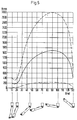
- the transmission 7 is in connection with the characteristic of Spring element 6 designed so that the course of the on Elbow axis 3 applied torque depending on Bending angle of the forearm fitting part 2 approximately parabolic is (see Figure 5) and its lowest values in the stretched position from about 10 ° to 20 ° and at maximum diffraction and Maximum at about 90 °.
- This is done with that in the figures 2 and 3 illustrated embodiments by a corresponding design of the curve of the two cams 7a, 7b, and by their association with one another, thus also a corresponding compensation of the spring force characteristic is made.
- the adjustable range this compensation are shown in FIG. 5 above the flexion angle of the forearm fitting part 2 applied torque lines.
- Figure 4 is indicated schematically that the adjustment of the Spring element 6 also via a first sensor 23 depending on the flexion controlled motor 24 can. This can be done by an electrical adjustment the spring force depending on the bending angle and the Change the torque curve.
- an additional torque provided on the forearm fitting part 2 motor 25 be. This allows the spring force to be increased electrically.
- a third motor 26 is indicated in FIG. 4, with which an electrical locking of the forearm fitting part 2 can be reached in a desired flexion position.
- a comparable one with that through the two cams 7a, 7b achieved kinematics by appropriate curve formation the driven pulley 12, the deflection roller 19 and / or achieve the contour 21.
Landscapes
- Health & Medical Sciences (AREA)
- Transplantation (AREA)
- Vascular Medicine (AREA)
- Life Sciences & Earth Sciences (AREA)
- Oral & Maxillofacial Surgery (AREA)
- Engineering & Computer Science (AREA)
- Biomedical Technology (AREA)
- Heart & Thoracic Surgery (AREA)
- Veterinary Medicine (AREA)
- Cardiology (AREA)
- Animal Behavior & Ethology (AREA)
- General Health & Medical Sciences (AREA)
- Public Health (AREA)
- Orthopedic Medicine & Surgery (AREA)
- Prostheses (AREA)
- Manipulator (AREA)
- Valve-Gear Or Valve Arrangements (AREA)
- Orthopedics, Nursing, And Contraception (AREA)
Description
- Figur 1 -
- im Längsschnitt und zum Teil in Seitenansicht eine komplette Armprothese mit gestrecktem Unterarm;
- Figur 2 -
- in vergrößertem Maßstab einen Ausschnitt der Figur 1;
- Figur 3 -
- die Darstellung gemäß Figur 2 jedoch mit stark angewinkeltem Unterarm;
- Figur 4 -
- eine mit zusätzlichen Elektroantrieben ausgerüstete Ausführungsform in einer Darstellung gemäß Figur 3 und
- Figur 5 -
- drei Drehmomentenverläufe, aufgetragen über den Beugewinkeln des Unterarmes.
Claims (16)
- Verfahren zum Aufbringen eines Drehmomentes auf die Ellbogenachse einer Oberarmprothese zur Verschwenkung des Unterarmes mit Hilfe einer Federkraft, dadurch gekennzeichnet, daß der Drehmomentenverlauf in Abhängigkeit vom Beugewinkel des Unterarmes im wesentlichen parabelförmig ist und seine niedrigsten Werte in der Strecklage von im wesentlichen 5° bis 25°, vorzugsweise 10° bis 20° sowie bei maximaler Beugung und sein Maximum bei im wesentlichen 90° aufweist.
- Verfahren nach Anspruch 1, dadurch gekennzeichnet, daß die Federkraft durch eine elektrische Verstellung in Abhängigkeit vom Beugewinkel sowie des Drehmomentenverlaufes verändert und/oder durch ein elektrisch aufgebrachtes, zusätzliches Drehmoment verstärkt wird.
- Ellbogenlifter für eine Armprothese, deren Oberarmpaßteil (1) über zumindest eine Ellbogenachse (3) gelenkig mit einem Unterarmpaßteil (2) verbunden ist, dessen Verschwenkung durch ein Federelement (6) des Ellbogenlifters unterstützt wird, gekennzeichnet durch ein Getriebe (7), dessen Eingang (17) von dem Federelement (6) mit einer Zugkraft beaufschlagt wird, und dessen Ausgang (18) an dem inneren Ende eines mit einem inneren und einem äußeren Ende versehenen Zugorgans (9) angreift, dessen äußeres Ende an einem mit der Ellbogenachse (3) einen Drehmomenthebel definierenden Fixpunkt (20) des Oberarmpaßteils (1) festlegbar ist, wobei die Kraftübertragung durch das Getriebe (7) so erfolgt, daß der Verlauf des am Fixpunkt (20) des Oberarmpaßteiles (1) angreifenden Drehmomentes in Abhängigkeit vom Beugewinkel des Unterarmpaßteils (2) im wesentlichen parabelförmig ist und seine niedrigsten Werte in der Strecklage von im wesentlichen 5° bis 25°, vorzugsweise 10° bis 20° sowie bei maximaler Beugung und sein Maximum bei im wesentlichen 90° aufweist.
- Ellbogenlifter nach Anspruch 3, gekennzeichnet durch seine Ausbildung als einteilige Baugruppe, die in eine Ausnehmung des Unterarmpaßteils (2) einsetzbar ist.
- Ellbogenlifter nach Anspruch 3 oder 4, dadurch gekennzeichnet, daß das Federelement (6) eine Spiralfeder ist.
- Ellbogenlifter nach Anspruch 3, 4 oder 5, dadurch gekennzeichnet, daß das Federelement (6) hinsichtlich seiner Zugkraft justierbar ausgebildet ist.
- Ellbogenlifter nach Anspruch 5 und 6, dadurch gekennzeichnet, daß eine Vorspannung des Federelementes (6) über ein Schneckenrad (14) justierbar ist.
- Ellbogenlifter nach Anspruch 6 oder 7, dadurch gekennzeichnet, daß die Justierung des Federelementes (6) über einen ersten, von einem Sensor (23) gesteuerten Motor (24) erfolgt.
- Ellbogenlifter nach einem der Ansprüche 3 bis 8, dadurch gekennzeichnet, daß das Federelement (6) als Drehkraft an einer Abtriebsscheibe (12) angreift, an der ein mit dem Getriebeeingang (17) in Verbindung stehendes Kraftübertragungselement (8) festgelegt ist.
- Ellbogenlifter nach einem der Ansprüche 3 bis 9, dadurch gekennzeichnet, daß das Getriebe (7) ein Kurvenscheibengetriebe ist.
- Ellbogenlifter nach Anspruch 10, gekennzeichnet durch folgende Merkmale:a) Das Kurvenscheibengetriebe (7) umfaßt zwei jeweils drehfest auf einer gemeinsamen Welle (10) sitzende Kurvenscheiben (7a,7b);b) das Kraftübertragungselement (8) ist ein biegeelastischer Riemen, der mit seinem einen Ende an dem Federelement (6) angreift, die erste (7a) der beiden Kurvenscheiben (7a,7b) bei gestreckter Armprothese weitgehend umschlingt und mit seinem anderen Ende an dieser ersten Kurvenscheibe (7a) an einem den Getriebeeingang (17) definierenden Punkt befestigt ist;c) das Zugorgan (9) ist ebenfalls biegeelastisch ausgebildet und ist mit seinem inneren Ende an einem den Getriebeausgang (18) definierenden Punkt der zweiten Kurvenscheibe (7b) befestigt, die von dem Zugorgan (9) bei zunehmender Beugung des Unterarmpaßteils (2) zunehmend unmschlungen wird.
- Ellbogenlifter nach Anspruch 11, dadurch gekennzeichnet, daß das von der zweiten Kurvenscheibe (7b) kommende Zugorgan (9) um eine Umlenkrolle (19) im wesentlichen tangential an die untere Kontur (21) des Oberarmpaßteils (1) herangeführt ist.
- Ellbogenlifter nach Anspruch 12, dadurch gekennzeichnet, daß das Zugorgan (9) bei gestreckter Armprothese im Bereich zwischen der Umlenkrolle (19) und dem Fixpunkt (20) am Oberarmpaßteil (1) an dessen unterer, im wesentlichen kreissegmentförmig ausgebildeter Kontur (21) anliegt.
- Ellbogenlifter nach einem der Ansprüche 3 bis 13, gekennzeichnet durch ein alle Bauteile aufnehmendes bzw. umschließendes Gehäuse (5).
- Ellbogenlifter nach einem der Ansprüche 3 bis 14, dadurch gekennzeichnet, daß im Bereich der Ellbogenachse (3) ein zweiter, ein zusätzliches Drehmoment auf das Unterarmpaßteil (2) aufbringender Motor (25) vorgesehen ist.
- Ellbogenlifter nach einem der Ansprüche 12 bis 15, dadurch gekennzeichnet, daß in die Umlenkrolle (19) eine hydrodynamische Dämpfung eingebaut ist.
Applications Claiming Priority (2)
| Application Number | Priority Date | Filing Date | Title |
|---|---|---|---|
| DE4324399 | 1993-07-21 | ||
| DE4324399A DE4324399C1 (de) | 1993-07-21 | 1993-07-21 | Ellbogenlifter |
Publications (2)
| Publication Number | Publication Date |
|---|---|
| EP0635247A1 EP0635247A1 (de) | 1995-01-25 |
| EP0635247B1 true EP0635247B1 (de) | 1998-11-04 |
Family
ID=6493318
Family Applications (1)
| Application Number | Title | Priority Date | Filing Date |
|---|---|---|---|
| EP94105939A Expired - Lifetime EP0635247B1 (de) | 1993-07-21 | 1994-04-16 | Ellbogenlifter |
Country Status (13)
| Country | Link |
|---|---|
| US (1) | US5549712A (de) |
| EP (1) | EP0635247B1 (de) |
| JP (1) | JP3251767B2 (de) |
| CN (1) | CN1081454C (de) |
| AT (1) | ATE172862T1 (de) |
| BR (1) | BR9402471A (de) |
| CA (1) | CA2125322C (de) |
| CZ (1) | CZ114494A3 (de) |
| DE (2) | DE4324399C1 (de) |
| ES (1) | ES2126665T3 (de) |
| SK (1) | SK58294A3 (de) |
| TR (1) | TR28034A (de) |
| TW (1) | TW268894B (de) |
Cited By (3)
| Publication number | Priority date | Publication date | Assignee | Title |
|---|---|---|---|---|
| US11564815B2 (en) | 2019-09-17 | 2023-01-31 | Victoria Hand Project | Upper arm prosthetic apparatus and systems |
| US11672675B2 (en) | 2015-06-26 | 2023-06-13 | Victoria Hand Project | Prosthetic wrist |
| US11957606B2 (en) | 2020-10-29 | 2024-04-16 | Victoria Hand Project | Low-cost prosthetic apparatus, methods, kits, and systems with improved force transfer elements |
Families Citing this family (33)
| Publication number | Priority date | Publication date | Assignee | Title |
|---|---|---|---|---|
| US5915673A (en) * | 1996-03-27 | 1999-06-29 | Kazerooni; Homayoon | Pneumatic human power amplifer module |
| US5865426A (en) | 1996-03-27 | 1999-02-02 | Kazerooni; Homayoon | Human power amplifier for vertical maneuvers |
| US5888235A (en) * | 1997-01-07 | 1999-03-30 | Sarcos, Inc. | Body-powered prosthetic arm |
| US5873734A (en) * | 1997-05-30 | 1999-02-23 | The Science Learning Workshop, Inc. | Biomechanical models |
| US8048279B2 (en) * | 1998-02-27 | 2011-11-01 | Scott Wade Powell | Method and apparatus for electrocoagulation of liquids |
| CN1241526C (zh) | 2000-11-15 | 2006-02-15 | 有限会社之攸美义肢制作所 | 人体矫正器 |
| JP4098729B2 (ja) * | 2004-02-04 | 2008-06-11 | 医療法人北辰会 | 回転負荷設定手段を有する関節補装具回転ジョイント、該回転ジョイントを用いた関節補装具及び該関節補装具の製作方法 |
| US20070012105A1 (en) * | 2005-07-13 | 2007-01-18 | Barnes-Jewish Hospital | Method and apparatus for resistive characteristic assessment |
| DE102005062083A1 (de) * | 2005-12-22 | 2007-07-05 | Otto Bock Healthcare Ip Gmbh & Co. Kg | Handprothese |
| DE102006012716B3 (de) * | 2006-03-17 | 2008-01-17 | Otto Bock Healthcare Ip Gmbh & Co. Kg | Gelenkeinrichtung |
| US20080000317A1 (en) | 2006-05-31 | 2008-01-03 | Northwestern University | Cable driven joint actuator and method |
| RU2343879C1 (ru) * | 2007-07-05 | 2009-01-20 | Федеральное государственное учреждение "Санкт-Петербургский научно-практический центр медико-социальной экспертизы, протезирования и реабилитации инвалидов им. Г.А. Альбрехта Федерального агентства по здравоохранению и социальному развитию" (ФГУ "СПбНЦЭР им. Альбрехта Росздрава") | Протез плеча |
| JP5607629B2 (ja) * | 2008-08-28 | 2014-10-15 | レイセオン カンパニー | 生体模倣機械継ぎ手 |
| WO2010025419A2 (en) * | 2008-08-28 | 2010-03-04 | Raytheon Sarcos, Llc | Method of sizing actuators for a biomimetic mechanical joint |
| WO2010025403A1 (en) | 2008-08-28 | 2010-03-04 | Raytheon Sarcos, Llc | Control logic for biomimetic joint actuators |
| JP5482983B2 (ja) * | 2009-02-20 | 2014-05-07 | 国立大学法人 名古屋工業大学 | 機械式自重補償装置 |
| JP4609589B2 (ja) * | 2009-10-21 | 2011-01-12 | カシオ計算機株式会社 | 筋力制御装置 |
| JP4557089B2 (ja) * | 2009-10-21 | 2010-10-06 | カシオ計算機株式会社 | 筋力制御装置 |
| JP5190900B2 (ja) * | 2010-06-07 | 2013-04-24 | 国立大学法人 東京大学 | 調整ユニット |
| ITMI20110415A1 (it) | 2011-03-15 | 2012-09-16 | Alberto Audenino | Arto artificiale passivo e procedimento realizzativo dell'arto artificiale passivo |
| JP2014073222A (ja) * | 2012-10-04 | 2014-04-24 | Sony Corp | 運動補助装置及び運動補助方法 |
| KR101637067B1 (ko) * | 2013-11-04 | 2016-07-06 | 김재국 | 관절 연결 구조를 갖는 조립체의 토크 제어 방법 및 장치 |
| CN103750926B (zh) * | 2014-01-27 | 2015-11-11 | 上海科生假肢有限公司 | 上肢假肢的仿生自由摆动机构 |
| WO2016065350A1 (en) * | 2014-10-24 | 2016-04-28 | Levitate Technologies, Inc. | Arm support systems |
| CN104382675B (zh) * | 2014-12-17 | 2016-08-24 | 徐贵升 | 基于快速成型的自身动力驱动假肢及其制造方法 |
| KR101677935B1 (ko) | 2015-04-07 | 2016-11-22 | 주식회사 에스지메카트로닉스 | 관절 구동기 및 이를 구비하는 하지 보조로봇의 관절구조 |
| DE102015113977A1 (de) * | 2015-08-24 | 2017-03-02 | Otto Bock Healthcare Products Gmbh | Künstliches Gelenk |
| CN105708585B (zh) * | 2016-01-20 | 2018-01-16 | 沈阳工业大学 | 基于线驱动差分关节的六自由度智能假臂 |
| WO2017212121A1 (fr) | 2016-06-08 | 2017-12-14 | Feltrin, Oscar | Prothèse d'avant bras à centre de gravité variable automatique |
| KR101706513B1 (ko) | 2016-10-12 | 2017-02-14 | 명지대학교 산학협력단 | 가변 토크 보상기 및 이를 이용하는 로봇 암 |
| ES2695502B2 (es) * | 2017-06-30 | 2019-11-18 | Torro Jorge Amoros | Brazo articulado |
| EP4384122A1 (de) * | 2021-08-09 | 2024-06-19 | Fondazione Istituto Italiano di Tecnologia | Gelenkprothese |
| WO2025248439A1 (en) | 2024-05-29 | 2025-12-04 | Fondazione Istituto Italiano Di Tecnologia | Robotic joint |
Family Cites Families (11)
| Publication number | Priority date | Publication date | Assignee | Title |
|---|---|---|---|---|
| US1644833A (en) * | 1925-11-03 | 1927-10-11 | Hoare Cyril George | Joint for elbows and knees of artificial limbs |
| US2537402A (en) * | 1946-06-17 | 1951-01-09 | Fitch And Sons Inc | Prosthetic appliance |
| US2516791A (en) * | 1948-04-06 | 1950-07-25 | Northrop Aircraft Inc | Artificial arm |
| US2592842A (en) * | 1948-07-10 | 1952-04-15 | Samuel W Alderson | Shoulder harness for artificial arms |
| US2553830A (en) * | 1949-05-07 | 1951-05-22 | Northrop Aircraft Inc | Elbow and lock mechanism for artificial arms |
| US2626398A (en) * | 1950-08-28 | 1953-01-27 | Orthopedic Equipment Co | Artificial arm |
| US3107358A (en) * | 1961-05-15 | 1963-10-22 | A J Hosmer Corp | Prosthetic joint |
| AT347024B (de) * | 1976-11-26 | 1978-12-11 | Orthopaedietech Forsch | Reibrad-getriebe fuer kunstglieder |
| US4604098A (en) * | 1984-07-17 | 1986-08-05 | The Johns Hopkins University | Prosthetic elbow with a motor-driven release mechanism |
| US4957281A (en) * | 1989-01-30 | 1990-09-18 | Wright State University | Rotator cuff therapeutic exercise apparatus |
| US5104121A (en) * | 1990-07-20 | 1992-04-14 | Nautilus Acquisition Corporation | Torso exercise machine with range limiter |
-
1993
- 1993-07-21 DE DE4324399A patent/DE4324399C1/de not_active Expired - Fee Related
- 1993-09-21 TW TW082107725A patent/TW268894B/zh not_active IP Right Cessation
-
1994
- 1994-04-16 EP EP94105939A patent/EP0635247B1/de not_active Expired - Lifetime
- 1994-04-16 DE DE59407209T patent/DE59407209D1/de not_active Expired - Lifetime
- 1994-04-16 AT AT94105939T patent/ATE172862T1/de active
- 1994-04-16 ES ES94105939T patent/ES2126665T3/es not_active Expired - Lifetime
- 1994-05-09 CZ CZ941144A patent/CZ114494A3/cs unknown
- 1994-05-12 TR TR00440/94A patent/TR28034A/xx unknown
- 1994-05-17 SK SK582-94A patent/SK58294A3/sk unknown
- 1994-05-24 JP JP10998794A patent/JP3251767B2/ja not_active Expired - Fee Related
- 1994-06-07 CA CA002125322A patent/CA2125322C/en not_active Expired - Lifetime
- 1994-06-17 BR BR9402471A patent/BR9402471A/pt not_active IP Right Cessation
- 1994-07-08 US US08/272,036 patent/US5549712A/en not_active Expired - Lifetime
- 1994-07-11 CN CN94107844A patent/CN1081454C/zh not_active Expired - Lifetime
Cited By (3)
| Publication number | Priority date | Publication date | Assignee | Title |
|---|---|---|---|---|
| US11672675B2 (en) | 2015-06-26 | 2023-06-13 | Victoria Hand Project | Prosthetic wrist |
| US11564815B2 (en) | 2019-09-17 | 2023-01-31 | Victoria Hand Project | Upper arm prosthetic apparatus and systems |
| US11957606B2 (en) | 2020-10-29 | 2024-04-16 | Victoria Hand Project | Low-cost prosthetic apparatus, methods, kits, and systems with improved force transfer elements |
Also Published As
| Publication number | Publication date |
|---|---|
| TW268894B (de) | 1996-01-21 |
| SK58294A3 (en) | 1995-03-08 |
| BR9402471A (pt) | 1995-03-28 |
| JPH07144007A (ja) | 1995-06-06 |
| DE4324399C1 (de) | 1995-02-09 |
| CA2125322C (en) | 2003-09-30 |
| TR28034A (tr) | 1996-01-10 |
| CA2125322A1 (en) | 1995-01-22 |
| DE59407209D1 (de) | 1998-12-10 |
| EP0635247A1 (de) | 1995-01-25 |
| ATE172862T1 (de) | 1998-11-15 |
| CN1102777A (zh) | 1995-05-24 |
| ES2126665T3 (es) | 1999-04-01 |
| US5549712A (en) | 1996-08-27 |
| CN1081454C (zh) | 2002-03-27 |
| JP3251767B2 (ja) | 2002-01-28 |
| CZ114494A3 (en) | 1995-02-15 |
Similar Documents
| Publication | Publication Date | Title |
|---|---|---|
| EP0635247B1 (de) | Ellbogenlifter | |
| EP0672398B1 (de) | Schwenkverbindung zwischen Teilen eines orthopädischen Hilfsmittels | |
| DE102009037898B4 (de) | Greifeinrichtung | |
| EP1962733B1 (de) | Handprothese sowie kraftübertragungseinrichtung | |
| DE69226268T2 (de) | Kniegelenkprothese | |
| EP0590386B1 (de) | Gelenk in orthopädischen Prothesen und Orthesen | |
| DE19908851A1 (de) | Marknagel zur Knochendistraktion | |
| EP3352710B1 (de) | Protheseneinrichtung | |
| DE602005004453T2 (de) | Gelenkmechanismus mit zwei Aktuatoren für eine Roboterhand und dergleichen | |
| DE602005004956T2 (de) | Gelenkmechanismus mit zwei Aktuatoren für eine Roboterhand und dergleichen | |
| EP0045818A1 (de) | Handprothese | |
| DE3929825C2 (de) | Binokulares Fernrohr | |
| WO2016187636A1 (de) | Arm-exoskelett | |
| DE4020882A1 (de) | Wechselwirkende hueftbewegungsvorrichtung | |
| DE2819976C2 (de) | Gelenkarm mit umhüllter Parallelogrammfunktion | |
| DE3322199A1 (de) | Roboterarm | |
| WO2019052805A1 (de) | Gelenkeinrichtung | |
| DE3423432C2 (de) | Vorrichtung zur Positionierung einer Probe | |
| DE102012212094B4 (de) | Endoskopisches Instrument | |
| DE2752325C2 (de) | Endoskop mit Steuereinrichtung für die Biegung eines Endabschnittes | |
| EP4376730B1 (de) | Chirurgisches instrument und lenkgetriebe dafür | |
| DE19935058B4 (de) | Gelenkschienensystem mit unabhängig handhabbarer Fixierung | |
| EP4376728B1 (de) | Chirurgisches instrument und lenkgetriebe dafür | |
| EP3090708A1 (de) | Knieorthese zum aufbringen einer ventral oder dorsal gerichteten translationskraft | |
| DE9320708U1 (de) | Ellbogenlifter |
Legal Events
| Date | Code | Title | Description |
|---|---|---|---|
| PUAI | Public reference made under article 153(3) epc to a published international application that has entered the european phase |
Free format text: ORIGINAL CODE: 0009012 |
|
| 17P | Request for examination filed |
Effective date: 19941129 |
|
| AK | Designated contracting states |
Kind code of ref document: A1 Designated state(s): AT BE CH DE ES FR GB IT LI LU NL SE |
|
| 17Q | First examination report despatched |
Effective date: 19970430 |
|
| GRAG | Despatch of communication of intention to grant |
Free format text: ORIGINAL CODE: EPIDOS AGRA |
|
| GRAG | Despatch of communication of intention to grant |
Free format text: ORIGINAL CODE: EPIDOS AGRA |
|
| GRAH | Despatch of communication of intention to grant a patent |
Free format text: ORIGINAL CODE: EPIDOS IGRA |
|
| GRAH | Despatch of communication of intention to grant a patent |
Free format text: ORIGINAL CODE: EPIDOS IGRA |
|
| GRAA | (expected) grant |
Free format text: ORIGINAL CODE: 0009210 |
|
| AK | Designated contracting states |
Kind code of ref document: B1 Designated state(s): AT BE CH DE ES FR GB IT LI LU NL SE |
|
| REF | Corresponds to: |
Ref document number: 172862 Country of ref document: AT Date of ref document: 19981115 Kind code of ref document: T |
|
| REG | Reference to a national code |
Ref country code: CH Ref legal event code: NV Representative=s name: BRAUN & PARTNER PATENT-, MARKEN-, RECHTSANWAELTE Ref country code: CH Ref legal event code: EP |
|
| GBT | Gb: translation of ep patent filed (gb section 77(6)(a)/1977) |
Effective date: 19981104 |
|
| REF | Corresponds to: |
Ref document number: 59407209 Country of ref document: DE Date of ref document: 19981210 |
|
| ITF | It: translation for a ep patent filed | ||
| ET | Fr: translation filed | ||
| REG | Reference to a national code |
Ref country code: ES Ref legal event code: FG2A Ref document number: 2126665 Country of ref document: ES Kind code of ref document: T3 |
|
| PLBE | No opposition filed within time limit |
Free format text: ORIGINAL CODE: 0009261 |
|
| STAA | Information on the status of an ep patent application or granted ep patent |
Free format text: STATUS: NO OPPOSITION FILED WITHIN TIME LIMIT |
|
| 26N | No opposition filed | ||
| PGFP | Annual fee paid to national office [announced via postgrant information from national office to epo] |
Ref country code: LU Payment date: 20010402 Year of fee payment: 8 |
|
| REG | Reference to a national code |
Ref country code: GB Ref legal event code: IF02 |
|
| PG25 | Lapsed in a contracting state [announced via postgrant information from national office to epo] |
Ref country code: LU Free format text: LAPSE BECAUSE OF NON-PAYMENT OF DUE FEES Effective date: 20020416 |
|
| PGFP | Annual fee paid to national office [announced via postgrant information from national office to epo] |
Ref country code: BE Payment date: 20050421 Year of fee payment: 12 |
|
| PGFP | Annual fee paid to national office [announced via postgrant information from national office to epo] |
Ref country code: CH Payment date: 20050503 Year of fee payment: 12 |
|
| PG25 | Lapsed in a contracting state [announced via postgrant information from national office to epo] |
Ref country code: LI Free format text: LAPSE BECAUSE OF NON-PAYMENT OF DUE FEES Effective date: 20060430 Ref country code: CH Free format text: LAPSE BECAUSE OF NON-PAYMENT OF DUE FEES Effective date: 20060430 Ref country code: BE Free format text: LAPSE BECAUSE OF NON-PAYMENT OF DUE FEES Effective date: 20060430 |
|
| REG | Reference to a national code |
Ref country code: CH Ref legal event code: PL |
|
| BERE | Be: lapsed |
Owner name: OTTO *BOCK ORTHOPADISCHE INDUSTRIE BESITZ- UND VER Effective date: 20060430 |
|
| PGFP | Annual fee paid to national office [announced via postgrant information from national office to epo] |
Ref country code: ES Payment date: 20120423 Year of fee payment: 19 |
|
| PGFP | Annual fee paid to national office [announced via postgrant information from national office to epo] |
Ref country code: AT Payment date: 20120420 Year of fee payment: 19 |
|
| PGFP | Annual fee paid to national office [announced via postgrant information from national office to epo] |
Ref country code: SE Payment date: 20130423 Year of fee payment: 20 Ref country code: GB Payment date: 20130422 Year of fee payment: 20 Ref country code: DE Payment date: 20130515 Year of fee payment: 20 |
|
| PGFP | Annual fee paid to national office [announced via postgrant information from national office to epo] |
Ref country code: FR Payment date: 20130523 Year of fee payment: 20 Ref country code: IT Payment date: 20130424 Year of fee payment: 20 Ref country code: NL Payment date: 20130422 Year of fee payment: 20 |
|
| REG | Reference to a national code |
Ref country code: DE Ref legal event code: R071 Ref document number: 59407209 Country of ref document: DE |
|
| REG | Reference to a national code |
Ref country code: NL Ref legal event code: V4 Effective date: 20140416 |
|
| REG | Reference to a national code |
Ref country code: GB Ref legal event code: PE20 Expiry date: 20140415 |
|
| REG | Reference to a national code |
Ref country code: SE Ref legal event code: EUG |
|
| REG | Reference to a national code |
Ref country code: AT Ref legal event code: MK07 Ref document number: 172862 Country of ref document: AT Kind code of ref document: T Effective date: 20140416 |
|
| REG | Reference to a national code |
Ref country code: ES Ref legal event code: FD2A Effective date: 20140707 |
|
| PG25 | Lapsed in a contracting state [announced via postgrant information from national office to epo] |
Ref country code: GB Free format text: LAPSE BECAUSE OF EXPIRATION OF PROTECTION Effective date: 20140415 |
|
| PG25 | Lapsed in a contracting state [announced via postgrant information from national office to epo] |
Ref country code: DE Free format text: LAPSE BECAUSE OF EXPIRATION OF PROTECTION Effective date: 20140417 |
|
| PG25 | Lapsed in a contracting state [announced via postgrant information from national office to epo] |
Ref country code: ES Free format text: LAPSE BECAUSE OF EXPIRATION OF PROTECTION Effective date: 20140417 |