EP0635367B1 - Dispositif de positionnement de clichés sur le cylindre porte-plaque d'une machine d'impression - Google Patents
Dispositif de positionnement de clichés sur le cylindre porte-plaque d'une machine d'impression Download PDFInfo
- Publication number
- EP0635367B1 EP0635367B1 EP94111146A EP94111146A EP0635367B1 EP 0635367 B1 EP0635367 B1 EP 0635367B1 EP 94111146 A EP94111146 A EP 94111146A EP 94111146 A EP94111146 A EP 94111146A EP 0635367 B1 EP0635367 B1 EP 0635367B1
- Authority
- EP
- European Patent Office
- Prior art keywords
- register
- printing
- plate
- cylinder
- register pins
- Prior art date
- Legal status (The legal status is an assumption and is not a legal conclusion. Google has not performed a legal analysis and makes no representation as to the accuracy of the status listed.)
- Expired - Lifetime
Links
- 238000007639 printing Methods 0.000 title claims abstract description 46
- 230000003287 optical effect Effects 0.000 claims description 4
- 239000000725 suspension Substances 0.000 claims description 3
- 230000002093 peripheral effect Effects 0.000 claims 3
- 102000001999 Transcription Factor Pit-1 Human genes 0.000 description 7
- 108010040742 Transcription Factor Pit-1 Proteins 0.000 description 7
- 238000007645 offset printing Methods 0.000 description 4
- 238000012937 correction Methods 0.000 description 3
- 238000004080 punching Methods 0.000 description 3
- 238000001514 detection method Methods 0.000 description 2
- 239000000919 ceramic Substances 0.000 description 1
- 239000003086 colorant Substances 0.000 description 1
- 238000011161 development Methods 0.000 description 1
- 230000018109 developmental process Effects 0.000 description 1
- 238000006073 displacement reaction Methods 0.000 description 1
- 230000000694 effects Effects 0.000 description 1
- 238000005516 engineering process Methods 0.000 description 1
- 210000003746 feather Anatomy 0.000 description 1
- 238000009434 installation Methods 0.000 description 1
- 239000000463 material Substances 0.000 description 1
- 238000005259 measurement Methods 0.000 description 1
- 239000002184 metal Substances 0.000 description 1
- 238000000034 method Methods 0.000 description 1
- 239000002699 waste material Substances 0.000 description 1
Images
Classifications
-
- B—PERFORMING OPERATIONS; TRANSPORTING
- B41—PRINTING; LINING MACHINES; TYPEWRITERS; STAMPS
- B41F—PRINTING MACHINES OR PRESSES
- B41F27/00—Devices for attaching printing elements or formes to supports
- B41F27/005—Attaching and registering printing formes to supports
Definitions
- the invention relates to a device for registering printing plates on the plate cylinder of printing machines according to the preamble of claim 1.
- a printing plate In sheet-fed offset printing machines, a printing plate is inserted with its front edge into a tensioning rail assigned to the start of printing of the plate cylinder and located in an axially parallel pit, pulled around the outer circumference of the plate cylinder and then inserted with its rear edge into a tensioning rail assigned to the printing end, clamped and then tensioned.
- any necessary corrections to compensate for the warpage of the printing material are then either compensated for by adjusting the cylinders relative to one another or by changing the position of the printing plates on the cylinders - adjustable tensioning rails at the beginning and / or end of printing.
- register systems are used to ensure that printing plates are placed on the plate cylinder of printing machines, in particular sheetfed offset printing machines, in register has been developed. These usually consist of punched holes or perforations on the printing start area of the printing plate, which interact with corresponding dowel pins fixed on the plate cylinder body (plate cylinder-related register system).
- Such cylinder-related register systems are mostly used when the tensioning rail assigned to the start of printing cannot be adjusted, since the punched holes or perforations in the printing plate cannot change position in the printing plate due to the cylinder-fixed position of the dowel pins, and are only possible to a minimal extent.
- register system generally uses U-shaped punchings on the edge of the printing plate associated with the start of printing and in the dowel pins which are adjustably mounted with respect to the plate cylinder. To register a pressure plate in register, the tensioning rail must therefore always be brought into a basic position, a so-called zero position, which is done by turning the tensioning screws that enable the adjustment.
- register systems are also referred to as slide rail-related register systems.
- dowel pins are designed as spring bolts which cooperate with dowel holes in the pressure plate.
- Each spring bolt or dowel pin is attached to a bracket which can be pivoted in the circumferential direction of the plate cylinder.
- a measuring device is assigned to the dowel pins or spring bolts, by means of which the pivoting thereof and thus the displacement of the pressure plate can be detected in the circumferential direction. It is therefore a cylinder-related register system which, to a certain extent, still permits changes in the position of the printing plate in the circumferential direction and also detects them by measurement technology.
- the disadvantage here is that the dowel pins cooperate with perforations at the pressure start area of the pressure plate and thus it is difficult to insert the pressure plate quickly into the tensioning rail.
- the object of the present invention is thus to develop a device according to the preamble of claim 1 in such a way that with simple constructional effort both the correct placement of the pressure plate in the front tensioning rail and the targeted tensioning of the start of pressure of an already tensioned pressure plate in the zero position of the pressure start tensioning rail can be detected.
- the second advantage of the attachment of the electrically interrogable dowel pins according to the invention is that an effect which is frequently observed in practice can be counteracted after the clamping of a printing plate over the end of the printing in a relatively simple manner.
- the pressure plate After the pressure plate has been inserted into the front and open tensioning rails and the correct position has been indicated by the LEDs lighting up, the pressure plate is tensioned over the end of the print. In the case of very high clamping forces, it can happen that the pressure plate is again pulled out a little bit from the register-oriented arrangement of the punched-out holes with respect to the dowel pins. The electrically closed contact between the pressure plate dowel pin is thus lost again.
- By simple Retensioning the pressure plate via the tensioning screws of the front tensioning rail can now bring the pressure plate with its punched out into contact with the dowel pins.
- Another advantage of the attachment of the electrically interrogated dowel pins according to the invention is that the pressure plate can also be moved by larger amounts via the tensioning screws of the front tensioning rail for register corrections, without the dowel pins actually representing a cylinder-related register system damaging the pressure plate.
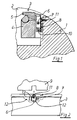
- the tensioning rail 3 assigned to the start of pressure is movably attached to the bottom of the pit 2 with respect to the plate cylinder 1 by means not shown (linear guide) and likewise cannot clamping screws shown are moved almost in the circumferential direction of the plate cylinder 1.
- the tensioning rail 3 consists of a lower and an upper terminal block 4, 5, the movable attachment as well the clamping screws, not shown, are assigned to the lower terminal strip 4.
- a pressure plate 9 inserted between the lower and upper clamping bar is clamped by pivoting an indicated profile shaft with a flattened portion, as a result of which the pivotable upper clamping bar 5 is pressed against the lower clamping bar 4.
- Such a clamping mechanism in tensioning rails is generally known and therefore requires no further explanation.
- pin-shaped dowel pins 6 are pivotably arranged on the wall of the pit 2 assigned to the start of printing, each on a pivot axis 7 and a holder 8 attached to the cylinder.
- the front tensioning rail 3 has a total of 2 axially spaced dowel pins 6, which cooperate with appropriately designed U-shaped punched-outs on the pressure plate front edge. In particular, it can be two differently shaped punched-outs which cooperate with round or otherwise shaped dowel pins 6.
- the holder 8 for the pivot axis 7 is essentially designed as a plate screwed to the wall of the plate cylinder 1 assigned to the start of the pit 2, on which two webs project in the direction of the tensioning rail 2, through which the pivot axis 7 is inserted for example in the form of a bolt.
- the pivot axis 7 is also inserted through a corresponding bore in the shaft of the dowel pin 6, as a result of which, as can be seen in FIG. 1, it can be pivoted in the manner of a double-armed lever.
- a spring 10 is arranged between the latter and the mounting plate of the holder 8, which presses the locating pin 6 against a stop 11 which is fixed on the cylinder.
- This stop 11 is designed in particular as an adjusting screw, by means of which the dowel pin 6 can be brought with its central axis or its contour into the zero position that defines the register-correct contact position.
- the dowel pin 6 itself or part of the dowel pin 6 is electrically insulated from the plate cylinder 1 and the clamping rail 3. This can be achieved, for example, in that the outer surface of the dowel pin 6 is coated with ceramic and a conductive metal layer is also attached to this electrically insulating layer. Conducting means, not shown, as well as a power supply, also not shown, thus produce an electrically interrogable contact which is closed exactly when the pressure plate with its punched-outs is correctly attached to the outer contour of the dowel pin 6. In this embodiment it is also shown that a light-emitting diode 13 is attached to the front end of the dowel pin 6, which lights up in particular in a specific color if and only if the pressure plate 9 is correctly in contact with the dowel pin 6.
- a recess 12 is arranged in the tensioning rail 3 both in the lower and in the upper terminal strip 4, 5 in the region of the pivotable suspension of the dowel pins 6 according to the invention formed via the holder 8 and the pivot axis 7 , so that the dowel pins 6 are in the detection or clamping area of the tensioning rail 3.
- the dowel pins 6 in the region of the recess 12 thus occupy exactly the location that a dowel pin 6 would have, which is mounted directly in the tensioning rail 3 in a conventional manner.
- the recess 12 in the area of the lower terminal strip 4 for receiving the holder 8 is larger than the recess 12 in the upper terminal strip 5. This is recognizable only slightly larger than the outer contour of the dowel pin 6.
- a pressure plate 9 is inserted into the open detection areas of the tensioning rail 3 between the lower and upper terminal strips 4, 5. After the U-shaped punchings within the pressure plate 9 have bridged the corresponding electrical contacts of the dowel pins 6, the light-emitting diodes 13 in the dowel pins 6 light up, which signals a correct contact of the pressure plate 9 with the dowel pins 6. So that the battery of the power supply for the LEDs 13 is protected, it can be provided that the LED display can be switched on and off by a manually operated switch in the pit 2.
- the pivotable suspension of the dowel pins 6 allows the printing plate 9 to be pulled in the direction of the center of the pit 2 of plate cylinder 1 via the normal position of the dowel pins 6 .
- the dowel pins 6 and the pivot axis 7 are simultaneously pivoted compressing the spring 10.
Landscapes
- Supply, Installation And Extraction Of Printed Sheets Or Plates (AREA)
- Rotary Presses (AREA)
Claims (5)
- Dispositif pour le positionnement exact de plaques d'impression sur le cylindre porte-plaque de machines d'impression, en particulier des machines d'impression offset à feuilles, comportant un rail tendeur agencé dans une gorge parallèle à l'axe, associé au début d'impression de la plaque d'impression, réglable en direction périphérique et présentant une zone de prise pour recevoir et fixer le bord avant de la plaque d'impression, le bord avant de la plaque d'impression présentant des découpes en forme de U, qui coopèrent avec des goupilles d'assemblage associées au rail tendeur et pouvant être interrogées électriquement, ainsi qu'un indicateur optique pouvant être commuté par les goupilles d'assemblage pouvant être interrogées électriquement,
caractérisé en ce que les goupilles d'assemblage (6) sont agencées, en direction périphérique du cylindre porte-plaque (1), de façon pivotante sur le cylindre porte-plaque (1), en ce qu'à chaque goupille d'assemblage est associé un ressort (10), ainsi qu'une butée (11) solidaire du cylindre, au moyen desquels la goupille d'assemblage (6) prend, en direction périphérique, une position définissant une position de base du registre, et en ce que des évidements (12) sont prévus dans le rail tendeur (3), dans la zone des suspensions pivotantes (7,8) des goupilles d'assemblage (6) de sorte que les goupilles d'assemblage (6) sont situées dans la zone de prise pour la plaque d'impression (9) du rail tendeur (3). - Dispositif selon la revendication 1,
caractérisé en ce que les goupilles d'assemblage (6) pouvant être interrogées électriquement sont agencées sous forme de levier à double bras, par l'intermédiaire à chaque fois d'un élément de maintien (8) qui est fixé sur la paroi de la gorge (2) du cylindre porte-plaque (1), associée au début d'impression, avec un axe de pivotement (7), et le ressort (10) prenant appui de façon solidaire sur le cylindre agit sur la partie de la goupille d'assemblage (6), en regard du fond de la gorge (2), et la butée (11) est associée à l'extrémité de la goupille d'assemblage (6), en regard de la plaque d'impression (9). - Dispositif selon l'une des revendications 1 ou 2,
caractérisé en ce que la butée (11) est réalisée sous forme d'une vis de réglage. - Dispositif selon l'une des revendications précédentes,
caractérisé en ce que l'indicateur optique associé à la goupille d'assemblage (6) pouvant être interrogée électriquement, est agencé dans l'extrémité frontale de la goupille d'assemblage (6). - Dispositif selon la revendication 4,
caractérisé en ce que l'indicateur optique est réalisé, dans l'extrémité frontale de la goupille d'assemblage (6), sous forme d'une diode luminescente (13).
Applications Claiming Priority (2)
| Application Number | Priority Date | Filing Date | Title |
|---|---|---|---|
| DE9310987U DE9310987U1 (de) | 1993-07-22 | 1993-07-22 | Vorrichtung zum registerhaltigen Ansetzen von Druckplatten auf dem Plattenzylinder von Druckmaschinen |
| DE9310987U | 1993-07-22 |
Publications (2)
| Publication Number | Publication Date |
|---|---|
| EP0635367A1 EP0635367A1 (fr) | 1995-01-25 |
| EP0635367B1 true EP0635367B1 (fr) | 1997-02-19 |
Family
ID=6895932
Family Applications (1)
| Application Number | Title | Priority Date | Filing Date |
|---|---|---|---|
| EP94111146A Expired - Lifetime EP0635367B1 (fr) | 1993-07-22 | 1994-07-18 | Dispositif de positionnement de clichés sur le cylindre porte-plaque d'une machine d'impression |
Country Status (3)
| Country | Link |
|---|---|
| EP (1) | EP0635367B1 (fr) |
| AT (1) | ATE149018T1 (fr) |
| DE (2) | DE9310987U1 (fr) |
Families Citing this family (4)
| Publication number | Priority date | Publication date | Assignee | Title |
|---|---|---|---|---|
| JP3477356B2 (ja) * | 1997-03-27 | 2003-12-10 | リョービ株式会社 | 印刷機のクランプ駆動装置 |
| JP3711080B2 (ja) * | 2002-03-27 | 2005-10-26 | 富士写真フイルム株式会社 | シート材位置決め装置 |
| DE102021109488A1 (de) | 2021-04-15 | 2022-10-20 | Koenig & Bauer Ag | Vorrichtung zum Zuführen von Druckplatten und Verfahren zum Durchführen eines Plattenwechsels |
| DE102021122827A1 (de) | 2021-09-03 | 2023-03-09 | Koenig & Bauer Ag | Vorrichtung und Verfahren zum Zuführen von Druckplatten zu einem Plattenzylinder |
Family Cites Families (2)
| Publication number | Priority date | Publication date | Assignee | Title |
|---|---|---|---|---|
| US3456587A (en) * | 1966-04-11 | 1969-07-22 | American Photocopy Equip Co | Plate cylinder with retractable register pins |
| US4259904A (en) * | 1979-07-23 | 1981-04-07 | Heinz Metje | Alignment system for offset printing presses |
-
1993
- 1993-07-22 DE DE9310987U patent/DE9310987U1/de not_active Expired - Lifetime
-
1994
- 1994-07-18 AT AT94111146T patent/ATE149018T1/de not_active IP Right Cessation
- 1994-07-18 DE DE59401823T patent/DE59401823D1/de not_active Expired - Fee Related
- 1994-07-18 EP EP94111146A patent/EP0635367B1/fr not_active Expired - Lifetime
Also Published As
| Publication number | Publication date |
|---|---|
| EP0635367A1 (fr) | 1995-01-25 |
| DE59401823D1 (de) | 1997-03-27 |
| DE9310987U1 (de) | 1993-08-26 |
| ATE149018T1 (de) | 1997-03-15 |
Similar Documents
| Publication | Publication Date | Title |
|---|---|---|
| DE69303380T3 (de) | Vorrichtung zum Anbringen einer Platte auf einem Plattenzylinder | |
| EP0579017A1 (fr) | Dispositif pour tendre une plaque d'impression sur un cylindre de plaque | |
| DE4239089B4 (de) | Verfahren zur Registerkorrektur von Druckplatten | |
| DE19944936A1 (de) | Vorrichtung zur Voreinstellung der Druckanstellung un der Druckabstellung von Zylindern eines Druckwerks in einer Rotationsdruckmaschine | |
| EP0596337B1 (fr) | Dispositif pour placer en répérage des plaques d'impression sur des cylindres de plaque des machines | |
| DE4439623C2 (de) | Verfahren zum automatischen Zuführen von Druckplatten | |
| EP0967078B1 (fr) | Presse à bobines avec un mécanisme à mettre en pression et de mise hors-pression | |
| DE2804304C3 (de) | Mit biegsamen Druckplatten versehener Formzylinder für Rotationstiefdruckmaschinen | |
| EP0450155A1 (fr) | Procédé d'humidification et d'encrage d'un cliché positionné sur un cylindre porte-plaque | |
| EP1570985A2 (fr) | Dispositif pour régler la force de pression d'un rouleau réglable | |
| DE3409479C2 (fr) | ||
| EP0613777A2 (fr) | Dispositif pour ajuster le registre oblique dans un dispositif de serrage pour tendre des plaques d'impression dans une machine d'impression offset | |
| DE3220919C2 (de) | Druckwerk für eine von Schön- auf Schön- und Widerdruck umstellbaren Bogen-Rotations-Offsetdruckmaschine | |
| EP0635367A1 (fr) | Dispositif de positionnement de clichés sur le cylindre porte-plaque d'une machine d'impression | |
| DE10020648A1 (de) | Bogendruckmaschine | |
| EP0727311A1 (fr) | Dispositif pour échanger des plaques d'impression | |
| DE102005016309B4 (de) | Bogendruckmaschine | |
| DE3045164A1 (de) | "ausbaufaehige bogenoffset-rotationsdruckmaschine" | |
| DE19924785C2 (de) | Vorrichtung zum Befestigen von biegsamen Platten | |
| EP1528981A1 (fr) | Cylindres d'une presse rotative et unite d'impression | |
| CH651501A5 (en) | Sheet-fed rotary printing machine having at least one printing unit | |
| EP1466733B1 (fr) | Support pour une chambre de racle dans une rotatif à imprimer | |
| DE4410385C2 (de) | Vorrichtung zum Befestigen von Druckplatten | |
| DE3901175C2 (de) | Druckmaschine für Schön- oder Schön- und Widerdruck | |
| DE4125253C2 (de) | Farbkasten eines Farbwerks einer Druckmaschine mit einem Farbmesser |
Legal Events
| Date | Code | Title | Description |
|---|---|---|---|
| PUAI | Public reference made under article 153(3) epc to a published international application that has entered the european phase |
Free format text: ORIGINAL CODE: 0009012 |
|
| 17P | Request for examination filed |
Effective date: 19940729 |
|
| AK | Designated contracting states |
Kind code of ref document: A1 Designated state(s): AT BE CH DE FR GB IT LI |
|
| GRAG | Despatch of communication of intention to grant |
Free format text: ORIGINAL CODE: EPIDOS AGRA |
|
| GRAH | Despatch of communication of intention to grant a patent |
Free format text: ORIGINAL CODE: EPIDOS IGRA |
|
| GRAH | Despatch of communication of intention to grant a patent |
Free format text: ORIGINAL CODE: EPIDOS IGRA |
|
| 17Q | First examination report despatched |
Effective date: 19960722 |
|
| ITF | It: translation for a ep patent filed | ||
| GRAA | (expected) grant |
Free format text: ORIGINAL CODE: 0009210 |
|
| AK | Designated contracting states |
Kind code of ref document: B1 Designated state(s): AT BE CH DE FR GB IT LI |
|
| REF | Corresponds to: |
Ref document number: 149018 Country of ref document: AT Date of ref document: 19970315 Kind code of ref document: T |
|
| REG | Reference to a national code |
Ref country code: CH Ref legal event code: NV Representative=s name: E. BLUM & CO. PATENTANWAELTE Ref country code: CH Ref legal event code: EP |
|
| GBT | Gb: translation of ep patent filed (gb section 77(6)(a)/1977) |
Effective date: 19970219 |
|
| ET | Fr: translation filed | ||
| REF | Corresponds to: |
Ref document number: 59401823 Country of ref document: DE Date of ref document: 19970327 |
|
| ET | Fr: translation filed |
Free format text: CORRECTIONS |
|
| PLBE | No opposition filed within time limit |
Free format text: ORIGINAL CODE: 0009261 |
|
| STAA | Information on the status of an ep patent application or granted ep patent |
Free format text: STATUS: NO OPPOSITION FILED WITHIN TIME LIMIT |
|
| 26N | No opposition filed | ||
| PGFP | Annual fee paid to national office [announced via postgrant information from national office to epo] |
Ref country code: GB Payment date: 20010614 Year of fee payment: 8 |
|
| PGFP | Annual fee paid to national office [announced via postgrant information from national office to epo] |
Ref country code: CH Payment date: 20010618 Year of fee payment: 8 |
|
| PGFP | Annual fee paid to national office [announced via postgrant information from national office to epo] |
Ref country code: AT Payment date: 20010704 Year of fee payment: 8 |
|
| PGFP | Annual fee paid to national office [announced via postgrant information from national office to epo] |
Ref country code: BE Payment date: 20010713 Year of fee payment: 8 |
|
| REG | Reference to a national code |
Ref country code: GB Ref legal event code: IF02 |
|
| PGFP | Annual fee paid to national office [announced via postgrant information from national office to epo] |
Ref country code: FR Payment date: 20020711 Year of fee payment: 9 |
|
| PG25 | Lapsed in a contracting state [announced via postgrant information from national office to epo] |
Ref country code: GB Free format text: LAPSE BECAUSE OF NON-PAYMENT OF DUE FEES Effective date: 20020718 Ref country code: AT Free format text: LAPSE BECAUSE OF NON-PAYMENT OF DUE FEES Effective date: 20020718 |
|
| PG25 | Lapsed in a contracting state [announced via postgrant information from national office to epo] |
Ref country code: LI Free format text: LAPSE BECAUSE OF NON-PAYMENT OF DUE FEES Effective date: 20020731 Ref country code: CH Free format text: LAPSE BECAUSE OF NON-PAYMENT OF DUE FEES Effective date: 20020731 Ref country code: BE Free format text: LAPSE BECAUSE OF NON-PAYMENT OF DUE FEES Effective date: 20020731 |
|
| BERE | Be: lapsed |
Owner name: *MAN ROLAND DRUCKMASCHINEN A.G. Effective date: 20020731 |
|
| GBPC | Gb: european patent ceased through non-payment of renewal fee |
Effective date: 20020718 |
|
| REG | Reference to a national code |
Ref country code: CH Ref legal event code: PL |
|
| PG25 | Lapsed in a contracting state [announced via postgrant information from national office to epo] |
Ref country code: FR Free format text: LAPSE BECAUSE OF NON-PAYMENT OF DUE FEES Effective date: 20040331 |
|
| REG | Reference to a national code |
Ref country code: FR Ref legal event code: ST |
|
| PG25 | Lapsed in a contracting state [announced via postgrant information from national office to epo] |
Ref country code: IT Free format text: LAPSE BECAUSE OF NON-PAYMENT OF DUE FEES;WARNING: LAPSES OF ITALIAN PATENTS WITH EFFECTIVE DATE BEFORE 2007 MAY HAVE OCCURRED AT ANY TIME BEFORE 2007. THE CORRECT EFFECTIVE DATE MAY BE DIFFERENT FROM THE ONE RECORDED. Effective date: 20050718 |
|
| PGFP | Annual fee paid to national office [announced via postgrant information from national office to epo] |
Ref country code: DE Payment date: 20070719 Year of fee payment: 14 |
|
| PG25 | Lapsed in a contracting state [announced via postgrant information from national office to epo] |
Ref country code: DE Free format text: LAPSE BECAUSE OF NON-PAYMENT OF DUE FEES Effective date: 20090203 |