EP0635393A2 - Siège pour véhicules - Google Patents
Siège pour véhicules Download PDFInfo
- Publication number
- EP0635393A2 EP0635393A2 EP94115978A EP94115978A EP0635393A2 EP 0635393 A2 EP0635393 A2 EP 0635393A2 EP 94115978 A EP94115978 A EP 94115978A EP 94115978 A EP94115978 A EP 94115978A EP 0635393 A2 EP0635393 A2 EP 0635393A2
- Authority
- EP
- European Patent Office
- Prior art keywords
- support body
- seat
- cover layer
- flame
- layer
- Prior art date
- Legal status (The legal status is an assumption and is not a legal conclusion. Google has not performed a legal analysis and makes no representation as to the accuracy of the status listed.)
- Granted
Links
Images




Classifications
-
- A—HUMAN NECESSITIES
- A47—FURNITURE; DOMESTIC ARTICLES OR APPLIANCES; COFFEE MILLS; SPICE MILLS; SUCTION CLEANERS IN GENERAL
- A47C—CHAIRS; SOFAS; BEDS
- A47C31/00—Details or accessories for chairs, beds, or the like, not provided for in other groups of this subclass, e.g. upholstery fasteners, mattress protectors, stretching devices for mattress nets
- A47C31/02—Upholstery attaching means
-
- B—PERFORMING OPERATIONS; TRANSPORTING
- B60—VEHICLES IN GENERAL
- B60N—SEATS SPECIALLY ADAPTED FOR VEHICLES; VEHICLE PASSENGER ACCOMMODATION NOT OTHERWISE PROVIDED FOR
- B60N2/00—Seats specially adapted for vehicles; Arrangement or mounting of seats in vehicles
- B60N2/70—Upholstery springs ; Upholstery
-
- B—PERFORMING OPERATIONS; TRANSPORTING
- B29—WORKING OF PLASTICS; WORKING OF SUBSTANCES IN A PLASTIC STATE IN GENERAL
- B29D—PRODUCING PARTICULAR ARTICLES FROM PLASTICS OR FROM SUBSTANCES IN A PLASTIC STATE
- B29D99/00—Subject matter not provided for in other groups of this subclass
- B29D99/0092—Producing upholstery articles, e.g. cushions, seats
-
- B—PERFORMING OPERATIONS; TRANSPORTING
- B60—VEHICLES IN GENERAL
- B60N—SEATS SPECIALLY ADAPTED FOR VEHICLES; VEHICLE PASSENGER ACCOMMODATION NOT OTHERWISE PROVIDED FOR
- B60N2/00—Seats specially adapted for vehicles; Arrangement or mounting of seats in vehicles
- B60N2/58—Seat coverings
-
- B—PERFORMING OPERATIONS; TRANSPORTING
- B60—VEHICLES IN GENERAL
- B60N—SEATS SPECIALLY ADAPTED FOR VEHICLES; VEHICLE PASSENGER ACCOMMODATION NOT OTHERWISE PROVIDED FOR
- B60N2/00—Seats specially adapted for vehicles; Arrangement or mounting of seats in vehicles
- B60N2/58—Seat coverings
- B60N2/5816—Seat coverings attachments thereof
- B60N2/5875—Seat coverings attachments thereof by adhesion, e.g. gluing
-
- Y—GENERAL TAGGING OF NEW TECHNOLOGICAL DEVELOPMENTS; GENERAL TAGGING OF CROSS-SECTIONAL TECHNOLOGIES SPANNING OVER SEVERAL SECTIONS OF THE IPC; TECHNICAL SUBJECTS COVERED BY FORMER USPC CROSS-REFERENCE ART COLLECTIONS [XRACs] AND DIGESTS
- Y10—TECHNICAL SUBJECTS COVERED BY FORMER USPC
- Y10S—TECHNICAL SUBJECTS COVERED BY FORMER USPC CROSS-REFERENCE ART COLLECTIONS [XRACs] AND DIGESTS
- Y10S297/00—Chairs and seats
- Y10S297/01—Foam
-
- Y—GENERAL TAGGING OF NEW TECHNOLOGICAL DEVELOPMENTS; GENERAL TAGGING OF CROSS-SECTIONAL TECHNOLOGIES SPANNING OVER SEVERAL SECTIONS OF THE IPC; TECHNICAL SUBJECTS COVERED BY FORMER USPC CROSS-REFERENCE ART COLLECTIONS [XRACs] AND DIGESTS
- Y10—TECHNICAL SUBJECTS COVERED BY FORMER USPC
- Y10S—TECHNICAL SUBJECTS COVERED BY FORMER USPC CROSS-REFERENCE ART COLLECTIONS [XRACs] AND DIGESTS
- Y10S297/00—Chairs and seats
- Y10S297/05—Fireproof
Definitions
- the invention relates to a seat with a cushion made of foam plastic as described in the preamble of claim 1.
- a known seat with a cushion made of foam plastic - according to WO-A1 88/09731 by the same applicant - consists of a foam plastic with a support body made of an open-cell, elastic plastic foam with a first density and a flame-retardant layer made of an open-cell, flame-retardant, elastic foam plastic with a second density different from the first.
- a flame-resistant intermediate layer formed from high temperature-resistant fibers or threads laid in a grid or net-like manner.
- the plastic foam and the flame retardant layer are connected to one another, in particular by a foaming process, and are surrounded by a flame-retardant covering material.
- seats for public transport are already known - according to DE-GM 85 06 816 - which have a seat cushion which is covered with a seat cover, the seat cover and the seat cushion being made of a flame-retardant and low-smoke material.
- the procedure is such that a glass fiber mat is arranged between the flame-retardant seat cover and the seat cushion, which is usually made of plastic foam, to prevent the seat cover from burning through in the direction of the seat cushion.
- seat cushions made of different, flame-retardant, open-cell, flexible soft foams with different densities were glued together.
- Such a known vehicle seat - according to EP-A1 190 064 - consists of several layers of needle fleece, which are covered by a flame-retardant cover material. Reinforcement mats made of metal or glass fibers are arranged between the cover fabric and the individual layers of needle fleece to reduce damage caused by vandals. Due to the adhesive bonding of the individual layers and the multiple intermediate layers of this vandal protection layer, adequate ventilation is even more difficult to achieve in the known vehicle seat.
- the support body is formed from a part which has been foamed in one piece with flame retardants and the surface of which is covered with a flame retardant layer and then with a flame retardant cover material.
- a hard foam shell or a support frame with tension springs is provided, on which a seat cushion consisting of one or more foam pads is arranged.
- the foam layers can consist of a flame-retardant material.
- the seat cushion is covered with a fire protection cover and provided with a flame-retardant fabric cover on the side facing the user.
- the use of flame-retardant materials and the fire protection coating does achieve a slight improvement in the combustion behavior, but the volume loss when exposed to an open flame on the various foam layers cannot be reduced by such a structure.
- the invention has for its object to provide a seat for vehicles, in particular means of transport, such as rail vehicles or airplanes, which allows for sufficient air permeability and a favorable seating climate with the lowest possible weight and with a direct flame exposure for as long as possible the burn-off with less Oppose smoke development with a high resistance.
- this cover layer which is connected to the support body, is more resistant to tensile loads, such as are applied to the cover layer by holding devices for the cover material, than the flame-retardant layer previously used in this area, since the loads, which are introduced at certain points, are also distributed over a larger area of the cover layer the connection layer, for example the adhesive layer, is transferred between the cover layer and the support body.
- a further embodiment is described in claim 3. This embodiment makes it possible, without significantly increasing the total weight of such a seat cushion, to improve the erosion behavior of the seat cushion even when there is a flame load from below the seat.
- Another development according to claim 5 enables a partial, weight-saving reinforcement of the cover layer to adapt to the different load zone, especially in those areas in which the seat cushion rests on a support frame.
- An embodiment according to patent claim 6 is also advantageous, since as a result a thickness of the support body between the underside of a spring core facing the cover layer and this underside is kept as small as possible and a long service life of the seat cushion can nevertheless be achieved.
- a design according to claim 7 is also advantageous.
- the higher strength of the intermediate layer makes it even more difficult to burn through it, since with the charred residual materials remaining on the mesh or lattice of the intermediate layer when the flame retardant layer burns off, a dense protective or soot layer can be formed, which is not penetrated by the flames so quickly.
- an embodiment according to claim 8 is also advantageous, since this avoids melting of the supporting parts of the intermediate layer and thus prevents the same from collapsing.
- An embodiment of the support body according to claim 10 is also advantageous, since it can be produced in one work step from a one-piece molded part, for example in a foam shape corresponding to the desired spatial shape.
- a double seat 1 with two seats 2, 3 is shown.
- Each seat 2, 3 consists of a cushion 4 for a backrest and a seat cushion 5 for a seat.
- the cushion 4 and seat cushion 5 of the two seats 2 and 3 are identical built up but mirrored. But they can also be used for a single seat or a multiple seat.
- a seat 2 or 3 can also consist of a single or several cushions.
- the upholstery 4 and seat upholstery 5 are placed in a support frame, generally designated 6.
- the support frame 6 can also have any other shape.
- the seat cushion 5 is shown, which forms a seat.
- the seat cushion 5 comprises a support body 7, which preferably consists of a cold molded foam and is produced in a shape corresponding to the desired external dimensions of the support body 7. It consists of an elastic, open-cell plastic foam. It is preferably formed in one piece. As indicated schematically by small lines in the area of the hatching, the plastic foam can be mixed with a powdered flame retardant 8, for example with melamine resin and / or aluminum hydroxide.
- a powdered flame retardant 8 for example with melamine resin and / or aluminum hydroxide.
- On the upper side of the support body 7 there is an intermediate layer 9 made of high-temperature resistant threads 10 and 11 laid in a lattice or net shape.
- This intermediate layer 9 is covered by a flame retardant layer 12, which is provided on the side of the intermediate layer 9 facing away from the support body 7.
- This flame retardant layer 12 is impregnated with a liquid flame retardant.
- the liquid flame retardant contains, for example, chlorine, bromine or phosphorus. It is advantageous if the liquid flame retardant is mixed with aluminum oxide hydrate, the grain size distribution of which is preferably between 0.2 and 110 ⁇ m.
- This flame retardant layer 12 preferably consists of a polyether, the foam plastic forming part of a plastic foam block which is subsequently impregnated with a liquid flame retardant.
- the flame retardant layer 12, the intermediate layer 9, and the support body 7 are connected to one another in areas distributed over the surface by an adhesive 13, so that the air throughput of the seat cushion 5 is not significantly adversely affected by the adhesive 13.
- the flame retardant layer 12 is covered on the seat 14 with a flame-retardant cover material 15.
- the cover fabric 15 is connected to the seat cushion 5 by means of Velcro strips 16, which can be arranged in the region of a depression in the flame retardant layer 12.
- the intermediate layer 9 and the flame retardant layer 12 envelop the support body 7 in the region of the seat surface 14, which faces the person using the seat, and in the region of side surfaces 17.
- the flame-retardant cover material 15 can also cover these surfaces of the seat cushion 5 or the entire surface, but it is now also possible due to the structure of the seat cushion 5 according to the invention in those areas that cannot be seen - such as below the seat bench omit flame retardant cover fabric.
- the intermediate layer 9, which can also be formed, for example, by a knitted or woven fabric or fleece, net or grid, preferably has a mesh size of the threads laid in the form of a grid or mesh of approximately 0.5 to 8 mm, preferably 3 mm.
- a cover layer 19 is arranged on an underside 18 of the seat cushion 5.
- This cover layer consists of a flame-retardant woven or knitted fabric or a fleece made of non-combustible or flame-retardant fibers.
- Such flame retardant fabrics usually consist of a connection between cotton and polyester, e.g. 81% cotton and 19% polyester or 59% wool, 33% cotton and 8% polyester.
- the cover layer 19 is connected to the support body 7 by means of an adhesive 13, for example a continuous layer or, as shown in FIG. 2 for the intermediate layer 9 or the flame retardant layer 12, by means of individual adhesive points.
- an adhesive 13 for example a continuous layer or, as shown in FIG. 2 for the intermediate layer 9 or the flame retardant layer 12, by means of individual adhesive points.
- the support body 7 it is of course also possible for the support body 7 to be foamed directly onto this cover layer 19.
- the cover layer 19 would have to be inserted into an appropriate foam shape before the support body 7 is produced.
- this cover layer 19 overlaps or covers edges 20 to 23 between the side surfaces 17 and the underside 18.
- these parts 24 of the cover layer 19 projecting beyond the side surfaces 17 or the seat surface 14, the layers of the adhesive 13 between the support body 7 or the cover layer 19 and the flame protection layer 12 or the support body 7 and optionally the intermediate layer 9 can be covered. In the event of exposure to flame, this prevents the flames from penetrating into the interior of the seat cushion 5 due to the ignition of the adhesive.
- this overlapping or overlapping arrangement of the parts 24 of the cover layer 19 means that the flame retardant layer 12 or the intermediate layer 9 is detached reliably prevented by the support body 7.
- the Velcro strips 16 of a holding device for the flame-resistant cover fabric 15 are arranged on the side of the cover layer 19 facing away from the support body 7. These can preferably be connected to the cover layer 19 via a layer of adhesive 13.
- the advantage of this solution lies in the fact that the covering layer 19, which is connected to the supporting body 7 over a large area, provides a high degree of strength against detachment of the covering layer 19, due to the fact that it occurs in the area of the Velcro strip 16 when the flame-retardant covering material 15 is detached, and sometimes limited to small areas Tensile forces is avoided.
- this cover layer 19 it is also possible to provide reinforcement pads 25 on the side facing away from the support body 7, which can be used to prevent the cover layer 19 from being chafed, destroyed or torn open on the support frame 6 in the contact area of the seat cushion 5 .
- the seat cushion 5 is shown again in its front corner area on an enlarged scale. It can also be seen more clearly from this illustration that the cover fabric 15 is guided over the parts 24 of the cover layer 19 covering the side surface 17. Furthermore, it is also shown that, in addition to the cover layer 19, a flame-resistant cover material 15 can also be arranged on the underside 18 of the seat cushion 5. As already described with reference to FIG. 3, it may be expedient to arrange reinforcement supports 25 on the cover layer 19, by means of which the cover layer 19 can be supported on a support bar 26 of the support frame 6.
- the flame retardant 8 in the support body 7 is indicated by dashed lines.
- the support body 7 can be provided with recesses 27, for example caverns.
- the support body 7 made of foam plastic is connected to the cover layer 19 with the adhesive 13.
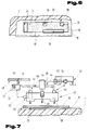
- the Velcro tape 16 has a carrier tape 29 made of a thermally deformable material, e.g. Polyamide.
- anchoring parts 31, e.g. a barb-shaped pile made of plastic or nylon fibers are arranged.
- the carrier tape 29 is thermally deformed in the direction of the cover layer 19, a depth 35 and a thickness 36 of the carrier tape 29 in the connection area being greater than a thickness 37 of the carrier tape 29 in the unembossed state, as a result of which the carrier tape 29 and the cover layer 19 interlock in the connection areas 34 in the manner of a toothing and form side surfaces 38.
- the heat-activatable adhesive 33 and the cover layer 19 are converted or plasticized in the connecting areas 34 into a viscous melt, as a result of which the materials flow into one another with a high level Adjusts the strength of the connection after solidification.
- the heat-activatable adhesive 33 can have an adhesive effect at room temperature in the higher range Forming temperature have a thin liquid, whereby penetration occurs both in the carrier tape 29 and in the cover layer 19.
- the anchoring parts 31 in the connection regions 34 can be thermally deformed or melted by the temperature effect of a heatable stamp 39.
- the melt penetrates into the fabric-shaped base material of the cover layer 19 and causes a firm welded connection after solidification.
- the adhesive force of the Velcro tape can be changed by the size of the total area.
- the Velcro tape 16 consists of the carrier tape 29, e.g. made of thermally deformable plastic, and the anchoring ring parts 31 arranged thereon. In the connection areas 34, the anchoring parts 31 are melted down after the application of pressure to the connection areas 34 and melted into the base material of the carrier tape 29 and the cover layer 19 as a melt.
- connection areas 34 can be arranged in any grid shape. So it is e.g. possible to arrange the connection areas 34 within the outline formed by the Velcro tape 16, but also to cover a side edge 40 of the Velcro tape 16. The durability and thus the pull-out strength of the connecting device 28 can thus be determined by the number, the arrangement and the size of the connecting areas 34. However, it is also possible to influence the number of anchoring parts 31, which determine the adhesive force of two interacting Velcro strips, by melting or uniforms in some areas, in order to reduce the holding force, if necessary, and thus to enable the cover fabric 15 to be released more easily.
- the Velcro tape 16 can thereby by the adhesive 33, for example a heat-activated Adhesive on the cover layer 19 be held prepositioned.
- the heating arrangement 41 is supplied with electrical energy from a power supply 48 via lines 49 and 50 via a control and regulating device 47 arranged upstream of the heating cartridges 42.
- a temperature sensor 51 is arranged in the press die 43 and is connected to the control and regulating device 47 via the line 52. As a result, the energy supply can be regulated in order to achieve a constant temperature of the press die 43 which is required for the method.
- Via another control element, e.g. a timer 53, and a pressure supply system 55 for the cylinder 45 can be controlled via a valve 54 and thus a holding time of the press die 43 for the fusion bonding of the Velcro tape 16 to the cover layer 19 can be achieved.
- the pressure force - arrow 58 - suitable for the method can also be regulated via a pressure relief valve 57 arranged in the pressure line 56 to the cylinder 45, as a result of which all parameters influencing the method can be preselected in accordance with the materials to be connected.
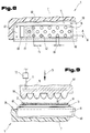
- FIGS. 8 and 9 an underside 59 of a seat cushion 5 is shown.
- This underside 59 is formed by a cover layer 19, for example made of a flame-retardant material, a net, knitted fabric or fleece made of natural or synthetic fibers, and is fastened on a support body 7, for example with the interposition of an adhesive layer 60.
- On this cover layer 19 there is a connecting device for connecting the same to the cover fabric 15 shown in FIG. 2, which is formed by a Velcro strip 16.
- This Velcro tape 16 is provided on its upper side with Velcro threads 61 which, when pressed on an opposite, become entangled with it and thus permit secure attachment or connection between two parts.
- connection areas 62, 63 In order to prevent high security against unintentional tearing or detachment of the connecting device or the Velcro strip 16 from the cover layer 19, the Velcro strip 16 is connected to the cover layer 19 in connection areas 62, 63.
- the Velcro tape 16 is positioned on the cover layer 19 via an adhesive layer 60. The positioning can also be done, for example, using brackets or other aids.
- the connecting regions 62, 63 in which the Velcro strip 16 is provided with thermally deformable materials or consist entirely of such thermally deformable materials are then heated, the Velcro threads, as is shown schematically in the drawing by a different representation, are deformed, which may reduce their adhesive properties if necessary.
- the connection areas 62 and 63 can now be designed differently, but it is also possible to find the length with the same or arranged connection areas.
- connection areas are arranged at a distance 64 which is a multiple of a diameter 65 of the connection areas 62.
- the rows of the connecting areas 62 are mutually offset by half the pitch and are arranged at a transverse distance 66, which can be slightly larger than the diameter 65 of the connecting areas 62.
- the total area of the connecting areas 62 in relation to the total area of the Velcro tape 16 can also change the adhesive force of the connecting device, in particular when the area portion of the connecting areas 62 or 63 makes up a large portion of the total area of the Velcro tape 16. This reduces the risk that the Velcro tape 16 can be torn off or torn off when the cover fabric 15 is removed from the cover layer 19.
- connection area 63 in the front end area of the Velcro tape 16 over the entire width 67 of the Velcro tape, so that detachment of the Velcro tape 16 from the cover layer 19 is reliably prevented even in the highly stressed end area.
- connection areas 62 it is also possible to divide the connection areas 62 to change as desired and to provide fewer connection areas per unit area of the Velcro tape 16 for low loads, and on the other hand it is also possible to use any surface shape for the connection areas instead of the circular design variant.
- FIG. 9 shows the seat cushion 5 in a front view, the support body 7 again showing the adhesive layer 60, the cover layer 19 and the Velcro strip 16 and the adhesive layer 60 connecting the Velcro strip 16 to the cover layer 19. It can also be seen that the Velcro threads 61 of the Velcro tape 16 are still undeformed.
- a press ram 68 is shown above the Velcro strip 16 and is provided with projections 69 or press noses. These projections 69 essentially have a cross section corresponding to the connecting regions 62 and 63, but are designed on their underside in the manner of a spherical cap or with an elliptical cross section.
- the entire press ram 68 is heated by means of heating rods 70, one of which is shown, which are connected via lines 71 to a control device 72 for regulating and monitoring the temperature.
- the control device 72 is connected to an energy source, for example a power supply network of an electrical supply company.
- the press ram 68 is now heated with the heating rods 70 to a temperature between 60 ° C. and 200 ° C., preferably 100 ° C.
- This temperature has the effect that the plastic of the Velcro tape, which is arranged at least in the connection areas 62 and 63, is plasticized or begins to melt and can penetrate into the underlying fiber structure of the cover layer 19. This is supported by the pressure force 73 applied with the press ram 68 - symbolically indicated by an arrow, so that the plasticized plastic is also pressed into the underlying tissue.
- the adhesive in the adhesive layer 60 is also heated and thus changes its flow behavior, with the pressure applied and the temperature effect achieving an even distribution of the adhesive or pressing it deeper into the cover layer 19, so that an intimate clawing and bonding between the adhesive and the cover layer 19 or the Velcro 16.
- a particularly intimate connection between the Velcro tape 16 and the cover layer 19 is achieved if the cover layer 19 has the smoothest possible surface in flow form or as a knitted fabric.
- FIG. 10 Another embodiment variant of a seat cushion 5 is shown in FIG. 10.
- the support body 7 of the seat cushion 5 consists of a central part 74, an enveloping layer 75 surrounding this central part and, in the region of the top and the side surfaces of the seat cushion 5, of an intermediate layer 9, a flame retardant layer 12 and the cover material 15.
- the central part 74 of the seat cushion 5 consists of a foam core 76 with a relatively high density between 60 kg and 150 kg per m3. The density is preferably 90 kg per m3.
- a spring core 77 is foamed into this foam core 78.
- This spring core 77 has a height 78 in a cushion 4, in particular the back cushion, which is less than a height 79 which is closer to the knees of the user.
- these different heights 78 and 79 of the spring core 77 can be achieved by a corresponding production of the spring core 77 or by a deformation of the spring core 77 during the production of the foam core 76.
- This foam core 76 which is relatively hard due to the high density, is surrounded by the covering layer 75, which can have a thickness of between 1 cm and 5 cm, preferably 3 cm.
- the density of this covering layer 75 is considerably less than that of the foam core 76 and is, for example, 40 kg to 45 kg per m3.
- This increase in seat resistance is additionally supported by the arrangement of the flame retardant layer 12, which is also made of plastic foam and is also relatively soft.
- an indentation 81 can be provided in an upper side 80 of the seat cushion 5, which in addition to the obliquely forward-rising formation of the seat cushion 5 prevents it from sliding forward in the direction of one of the cushion 4 , ie the back cushion, distant end face 82 of the seat cushion 5 is prevented.
- recesses 84 can be arranged in side surfaces 83, which extend into the interior of the foam core 76 through the covering layer 75, in order to provide appropriate moisture removal or a high level of air exchange during prolonged sitting to allow the seat cushion 5.
- a corresponding volume of air is exchanged with each movement through these recesses 84 or the cavities, with which a corresponding moisture in the form of water vapor can also be removed.
- FIG. 11 shows a plan view of the seat cushion 5, from which the recesses 84, which extend into the foam core 76, can be seen again.
- a possible shape of the depression 81 in the area of a user's buttocks on the seat cushion 5 is also shown. As can be seen, this recess 81 runs in the direction of the end face 82 of the seat cushion 5 in adaptation to the shape of the thighs of the users.
- FIG. 12 Another embodiment of a seat cushion 5 is shown in FIG. 12, the structure of which corresponds essentially to that in the exemplary embodiments described above, which is why the same reference numbers are used for the same parts.
- This seat cushion 5 has a spring core 85 in order to prevent the support body 7 from sitting through and the foam core collapsing due to this overload.
- a cover layer 19 is in turn arranged on the underside 18 of the seat cushion 5, while the flame retardant layer 12 in the region of the seat surface 14 is covered by a flame-retardant cover fabric 15, which also extends over the side surfaces 17 of the seat cushion 5.
- the edges 20 are again overlapped by the cover layer 19, whereby the advantages already described exist.
- an intermediate layer 9 of non-combustible or high-temperature resistant fibers or threads is arranged between the flame retardant layer 12 and the support body 7.
- this has connection points 86 between the individual parts of the spring core.
- a relatively high load is exerted on the layer of the support body between the end of the spring core 85 facing the underside 18 and the cover layer 19 when the seat is loaded in the direction of the arrow 87.
- reinforcement supports 25 are arranged, which may be strip-shaped.
- recesses 27 can also be arranged in the support body 7 in the case of seat cushions 5 provided with the flame-retardant layers according to the invention, in order to allow ventilation and thus moisture removal, especially when the To ensure a seat for longer trips, for example long-haul flights, is in use.
- an intermediate layer 9 in the manner already described, consisting of fibers or threads resistant to high temperatures, can also be arranged.
- the plastic foam from which the support body 7 is made can be formed by a cold molded foam which preferably has a density of between 15 and 60 kg / m3, preferably 40 kg / m3.
- This support body is further mixed with a powdered flame retardant 8, which can consist of melamine resin and / or aluminum hydroxide or a mixture of the two.
- the intermediate layer 9 is preferably formed from glass or carbon fiber mats, which can have a weight of 150 to 350 g / m2. This results in a favorable behavior between the weight gain when using this intermediate layer 9 and its flame retardant effect. However, intermediate layers 9 with a different weight can also be used.
- the high temperature resistant threads or fibers can be connected to one another in any way.
- woven and knitted fabrics made of these fibers or threads or threads consisting of such fibers can be used, and on the other hand a wide variety of materials can be used individually or mixed with one another in order to provide the greatest possible resistance to the flames from outside over a long period of time.
- glass, ceramic, graphite or high-temperature-resistant metals are preferably used as base materials for the threads and fibers.
- the flame retardant layer 12 preferably consists of a foam plastic with a density of about 20 to 60 kg / m3. Usually a polyether foam is used. Blocks are made from this polyether foam and after foaming, they are cut into sheets or strips with the desired layer thickness. These plates are then impregnated with a liquid flame retardant, a type 64 polyurethane (Bayer) being used as the flame retardant, parts by weight of which are mixed with 80 parts by weight of A1 (OH) 3. This aluminum oxide hydrate is stirred into the polyurethane.
- a type 64 polyurethane (Bayer) being used as the flame retardant, parts by weight of which are mixed with 80 parts by weight of A1 (OH) 3. This aluminum oxide hydrate is stirred into the polyurethane.
Landscapes
- Engineering & Computer Science (AREA)
- Mechanical Engineering (AREA)
- Aviation & Aerospace Engineering (AREA)
- Transportation (AREA)
- Mattresses And Other Support Structures For Chairs And Beds (AREA)
- Acyclic And Carbocyclic Compounds In Medicinal Compositions (AREA)
- Chair Legs, Seat Parts, And Backrests (AREA)
- Laminated Bodies (AREA)
- Seats For Vehicles (AREA)
- Passenger Equipment (AREA)
- Medicinal Preparation (AREA)
- Vehicle Waterproofing, Decoration, And Sanitation Devices (AREA)
- Compositions Of Macromolecular Compounds (AREA)
- Detection And Prevention Of Errors In Transmission (AREA)
- Developing Agents For Electrophotography (AREA)
- Eyeglasses (AREA)
- Organic Low-Molecular-Weight Compounds And Preparation Thereof (AREA)
- Vehicle Step Arrangements And Article Storage (AREA)
- Inorganic Insulating Materials (AREA)
- Magnetic Ceramics (AREA)
- Luminescent Compositions (AREA)
Applications Claiming Priority (7)
| Application Number | Priority Date | Filing Date | Title |
|---|---|---|---|
| AT10790A AT394163B (de) | 1990-01-18 | 1990-01-18 | Sitz, insbesondere fuer fahrzeuge |
| AT10790 | 1990-01-18 | ||
| AT107/90 | 1990-01-18 | ||
| AT35790 | 1990-02-15 | ||
| AT35790 | 1990-02-15 | ||
| AT357/90 | 1990-02-15 | ||
| PCT/AT1991/000006 WO1991010383A1 (fr) | 1990-01-18 | 1991-01-10 | Siege, en particulier pour vehicules |
Related Parent Applications (2)
| Application Number | Title | Priority Date | Filing Date |
|---|---|---|---|
| EP91902301A Division EP0511259B1 (fr) | 1990-01-18 | 1991-01-10 | Siege, en particulier pour vehicules |
| EP91902301.0 Division | 1991-01-10 |
Publications (3)
| Publication Number | Publication Date |
|---|---|
| EP0635393A2 true EP0635393A2 (fr) | 1995-01-25 |
| EP0635393A3 EP0635393A3 (fr) | 1995-11-22 |
| EP0635393B1 EP0635393B1 (fr) | 2000-11-22 |
Family
ID=25591473
Family Applications (2)
| Application Number | Title | Priority Date | Filing Date |
|---|---|---|---|
| EP91902301A Expired - Lifetime EP0511259B1 (fr) | 1990-01-18 | 1991-01-10 | Siege, en particulier pour vehicules |
| EP94115978A Expired - Lifetime EP0635393B1 (fr) | 1990-01-18 | 1991-01-10 | Siège pour véhicules |
Family Applications Before (1)
| Application Number | Title | Priority Date | Filing Date |
|---|---|---|---|
| EP91902301A Expired - Lifetime EP0511259B1 (fr) | 1990-01-18 | 1991-01-10 | Siege, en particulier pour vehicules |
Country Status (18)
| Country | Link |
|---|---|
| US (1) | US5405178A (fr) |
| EP (2) | EP0511259B1 (fr) |
| JP (1) | JPH05503023A (fr) |
| KR (1) | KR920702961A (fr) |
| CN (1) | CN1053398A (fr) |
| AT (2) | ATE197696T1 (fr) |
| AU (1) | AU659605B2 (fr) |
| BR (1) | BR9105927A (fr) |
| CA (1) | CA2073697A1 (fr) |
| DE (5) | DE59109203D1 (fr) |
| DK (1) | DK0511259T3 (fr) |
| ES (1) | ES2075954T3 (fr) |
| FI (1) | FI923246A7 (fr) |
| HK (1) | HK46096A (fr) |
| HU (1) | HUT63755A (fr) |
| MY (1) | MY104784A (fr) |
| NO (1) | NO922828L (fr) |
| WO (1) | WO1991010383A1 (fr) |
Cited By (1)
| Publication number | Priority date | Publication date | Assignee | Title |
|---|---|---|---|---|
| DE102012020555A1 (de) * | 2012-10-19 | 2014-04-24 | Johnson Controls Gmbh | Sitzteil für einen Fahrzeugsitz und damit ausgerüsteter Fahrzeugsitz |
Families Citing this family (48)
| Publication number | Priority date | Publication date | Assignee | Title |
|---|---|---|---|---|
| AT399488B (de) * | 1991-04-22 | 1995-05-26 | Greiner & Soehne C A | Sitzpolster, insbesondere flugzeugsitz |
| ATA20593A (de) * | 1993-02-05 | 1998-08-15 | Greiner & Soehne C A | Fahrzeugsitz, insbesondere für flugzeuge |
| AT409744B (de) * | 1996-09-20 | 2002-10-25 | Greiner & Soehne C A | Sitzpolsterteil wie aufsatzelement, tragelement sowie schutzschichte für einen sitzpolster |
| DE19845730B4 (de) * | 1998-10-05 | 2005-02-10 | Audi Ag | Polsterträger |
| US6158815A (en) * | 1998-12-24 | 2000-12-12 | Toyo Tire & Rubber Co., Ltd. | Seat having a seat cushion including a polyurethane foam pad onto a portion of which a stretchable, nonwoven fabric is laminated |
| US6884965B2 (en) * | 1999-01-25 | 2005-04-26 | Illinois Tool Works Inc. | Flexible heater device |
| US7202444B2 (en) * | 1999-01-25 | 2007-04-10 | Illinois Tool Works Inc. | Flexible seat heater |
| US7053344B1 (en) | 2000-01-24 | 2006-05-30 | Illinois Tool Works Inc | Self regulating flexible heater |
| US7306283B2 (en) | 2002-11-21 | 2007-12-11 | W.E.T. Automotive Systems Ag | Heater for an automotive vehicle and method of forming same |
| NL1022632C2 (nl) * | 2003-02-10 | 2004-08-12 | Recticel Nederland Bv | Zitting, alsmede zitinrichting voorzien van een dergelijke zitting. |
| US20050095936A1 (en) * | 2004-09-02 | 2005-05-05 | Jones Walter G. | Upholstery panels with fire resistant backing layer |
| US7406733B2 (en) * | 2005-05-13 | 2008-08-05 | Illinois Tool Works Inc. | Elastomeric fabric load bearing surface |
| JP4332882B2 (ja) * | 2005-09-21 | 2009-09-16 | テイ・エス テック株式会社 | 揮発物質の吸着性能付き自動車用シート |
| EP2051849B1 (fr) * | 2006-08-11 | 2010-03-31 | Basf Se | Garniture à protection ignifuge renforcée pour les sièges dans les moyens de transport et le secteur de l'ameublement |
| DE102008036646A1 (de) * | 2007-10-26 | 2009-04-30 | C. Rob. Hammerstein Gmbh & Co. Kg | Rahmenseitenteil eines Fahrzeugsitzes |
| BRPI0822846A2 (pt) * | 2008-10-22 | 2015-06-30 | Lear Corp | Estrutura deformável, laminado de acabamento, elemento de amortecimento para componentes do interior automotivo |
| JP5463903B2 (ja) * | 2009-12-24 | 2014-04-09 | トヨタ紡織株式会社 | 車両用シートのクッション材 |
| US8215714B2 (en) * | 2010-05-17 | 2012-07-10 | Lear Corporation | Vehicle seat assembly with interlocking layered seating system |
| US9191997B2 (en) | 2010-10-19 | 2015-11-17 | Gentherm Gmbh | Electrical conductor |
| DE102012000977A1 (de) | 2011-04-06 | 2012-10-11 | W.E.T. Automotive Systems Ag | Heizeinrichtung für komplex geformte Oberflächen |
| DE102011121979A1 (de) | 2011-09-14 | 2012-11-22 | W.E.T. Automotive Systems Ag | Temperier-Einrichtung |
| JP5747788B2 (ja) * | 2011-11-08 | 2015-07-15 | トヨタ紡織株式会社 | 車両用シート |
| DE102011121991B4 (de) * | 2011-12-22 | 2014-02-27 | Grammer Ag | Fahrzeugsitz und Verfahren zum Herstellen eines Fahrzeugsitzpolsterteils |
| US10201039B2 (en) | 2012-01-20 | 2019-02-05 | Gentherm Gmbh | Felt heater and method of making |
| DE202013003491U1 (de) | 2012-06-18 | 2013-09-20 | W.E.T. Automotive Systems Ag | Flächengebilde mit elektrischer Funktion |
| JP5960545B2 (ja) * | 2012-08-13 | 2016-08-02 | テイ・エス テック株式会社 | 車両用シート |
| DE102012017047A1 (de) | 2012-08-29 | 2014-03-06 | W.E.T. Automotive Systems Ag | Elektrische Heizeinrichtung |
| DE102012024903A1 (de) | 2012-12-20 | 2014-06-26 | W.E.T. Automotive Systems Ag | Flächengebilde mit elektrischen Funktionselementen |
| US20150360597A1 (en) * | 2014-06-13 | 2015-12-17 | Lear Corporation | Renewable fiber trim laminate |
| EP3197777B1 (fr) * | 2014-09-24 | 2021-06-02 | B/E Aerospace, Inc. | Ensemble fond de siège doté d'un ressort de confort encastré |
| CN104960446A (zh) * | 2015-07-14 | 2015-10-07 | 吉林大学 | 一种蜂巢式发泡结构座椅 |
| DE102016005387B3 (de) * | 2016-03-24 | 2017-02-16 | Oke Kunststofftechnik Gmbh & Co. Kg | Schaumstoffkern für ein Polster eines Sitzteils oder eines Liegeteils oder einer Rückenlehne eines Polstermöbels oder eines Fahrzeugsitzes |
| FR3062350B1 (fr) * | 2017-01-31 | 2022-11-04 | Peugeot Citroen Automobiles Sa | Coiffe d’habillage pour garniture d’assise ou de dossier de siege de vehicule automobile. |
| FR3062351B1 (fr) * | 2017-01-31 | 2019-03-29 | Peugeot Citroen Automobiles Sa | Coiffe d’habillage pour garniture d’assise ou de dossier de siege de vehicule automobile. |
| IT201700109132A1 (it) * | 2017-09-29 | 2019-03-29 | C & G Kiel Italia S R L | Rivestimento per sedili di mezzi di trasporto e metodo per la sua realizzazione |
| US11958393B2 (en) | 2019-01-14 | 2024-04-16 | Adient Us Llc | Seat assembly for a vehicle seat, method for assembling a seat assembly, and vehicle seat |
| US11712825B2 (en) * | 2019-09-10 | 2023-08-01 | Ford Global Technologies, Llc | Trim article having an integrated structural composition with variated densities and methods for making the same |
| US12269384B2 (en) | 2021-03-31 | 2025-04-08 | Lear Corporation | Seat support |
| US12319183B2 (en) * | 2021-03-31 | 2025-06-03 | Lear Corporation | Seat support |
| US12286043B2 (en) | 2021-10-06 | 2025-04-29 | Velcro Ip Holdings Llc | Seat cover fastening |
| US11807143B2 (en) * | 2021-12-02 | 2023-11-07 | Lear Corporation | Vehicle seating system and method for producing same |
| US12479143B2 (en) | 2021-12-20 | 2025-11-25 | Lear Corporation | System and method of making a mesh cushion |
| US12325168B2 (en) | 2021-12-20 | 2025-06-10 | Lear Corporation | System and method of making a mesh cushion |
| US12384094B2 (en) | 2022-03-08 | 2025-08-12 | Lear Corporation | Method for producing a vehicle interior component |
| US12454111B2 (en) | 2022-05-11 | 2025-10-28 | Lear Corporation | Tool to manufacture a cushion |
| US12509343B2 (en) | 2023-02-28 | 2025-12-30 | Lear Corporation | Automated trench manufacturing and assembly for attaching trim covers to a cushion assembly |
| US12325624B2 (en) | 2023-03-06 | 2025-06-10 | Lear Corporation | Seat assembly, cushion, and tool and method of forming |
| US12286044B2 (en) | 2023-05-12 | 2025-04-29 | Lear Corporation | Method and apparatus for producing a vehicle interior component |
Family Cites Families (13)
| Publication number | Priority date | Publication date | Assignee | Title |
|---|---|---|---|---|
| US3222698A (en) * | 1962-12-13 | 1965-12-14 | Gen Motors Corp | Resilient plastic seat elements |
| US4092751A (en) * | 1976-05-06 | 1978-06-06 | The Goodyear Tire & Rubber Company | Contoured foam seat |
| DE3111839A1 (de) * | 1981-03-26 | 1982-10-14 | Messerschmitt-Bölkow-Blohm GmbH, 8000 München | Fahrgastsitz in oeffentlichen verkehrsmitteln |
| JPS5980287A (ja) * | 1982-10-28 | 1984-05-09 | アイシン精機株式会社 | シ−ト |
| IE57148B1 (en) * | 1984-11-20 | 1992-05-06 | Velcro Ind | Separable fasteners as well as method and apparatus for adapting separable fasteners for attachment to other objects |
| FR2576200B1 (fr) * | 1985-01-21 | 1987-04-03 | Sofanor Sa | Revetement anti-vandalisme pour sieges |
| DE8505536U1 (de) * | 1985-02-27 | 1985-05-02 | Nickl, Alois, 8900 Augsburg | Vorrichtung zum Halten und Führen eines Gartengerätes |
| AT393108B (de) * | 1987-06-02 | 1991-08-26 | Greiner Schaumstoffwerk | Fahrzeugsitz, insbesondere flugzeugsitz, mit einer aus schaumkunststoff bestehenden polsterung |
| DE3853082D1 (de) * | 1987-06-02 | 1995-03-23 | Greiner & Soehne C A | Sitz mit einem Polster aus Schaumkunststoff. |
| US4792189A (en) * | 1988-02-04 | 1988-12-20 | Sears Mfg Co | Seat assembly |
| US5176424A (en) * | 1988-06-10 | 1993-01-05 | Mazda Motor Corporation | Automobile seat assembly |
| US5142757A (en) * | 1989-06-26 | 1992-09-01 | Christian Thary | Method of making an upholstered cushion article |
| GB9104895D0 (en) * | 1991-03-08 | 1991-04-24 | Gen Motors Corp | Upholstery fabric |
-
1991
- 1991-01-10 CA CA002073697A patent/CA2073697A1/fr not_active Abandoned
- 1991-01-10 WO PCT/AT1991/000006 patent/WO1991010383A1/fr not_active Ceased
- 1991-01-10 DE DE59109203T patent/DE59109203D1/de not_active Expired - Fee Related
- 1991-01-10 EP EP91902301A patent/EP0511259B1/fr not_active Expired - Lifetime
- 1991-01-10 BR BR919105927A patent/BR9105927A/pt unknown
- 1991-01-10 ES ES91902301T patent/ES2075954T3/es not_active Expired - Lifetime
- 1991-01-10 JP JP3502172A patent/JPH05503023A/ja active Pending
- 1991-01-10 DK DK91902301.0T patent/DK0511259T3/da active
- 1991-01-10 DE DE9117081U patent/DE9117081U1/de not_active Expired - Lifetime
- 1991-01-10 DE DE91AT9100006D patent/DE4190093D2/de not_active Expired - Lifetime
- 1991-01-10 AT AT94115978T patent/ATE197696T1/de not_active IP Right Cessation
- 1991-01-10 KR KR1019920701698A patent/KR920702961A/ko not_active Ceased
- 1991-01-10 HU HU921983A patent/HUT63755A/hu not_active IP Right Cessation
- 1991-01-10 AT AT91902301T patent/ATE123636T1/de not_active IP Right Cessation
- 1991-01-10 US US07/910,362 patent/US5405178A/en not_active Expired - Fee Related
- 1991-01-10 DE DE19914190093 patent/DE4190093A1/de not_active Withdrawn
- 1991-01-10 EP EP94115978A patent/EP0635393B1/fr not_active Expired - Lifetime
- 1991-01-10 DE DE59105730T patent/DE59105730D1/de not_active Expired - Fee Related
- 1991-01-10 AU AU71777/91A patent/AU659605B2/en not_active Ceased
- 1991-01-11 MY MYPI91000040A patent/MY104784A/en unknown
- 1991-01-18 CN CN91100309A patent/CN1053398A/zh active Pending
-
1992
- 1992-07-15 FI FI923246A patent/FI923246A7/fi not_active Application Discontinuation
- 1992-07-16 NO NO92922828A patent/NO922828L/no unknown
-
1996
- 1996-03-14 HK HK46096A patent/HK46096A/xx not_active IP Right Cessation
Cited By (1)
| Publication number | Priority date | Publication date | Assignee | Title |
|---|---|---|---|---|
| DE102012020555A1 (de) * | 2012-10-19 | 2014-04-24 | Johnson Controls Gmbh | Sitzteil für einen Fahrzeugsitz und damit ausgerüsteter Fahrzeugsitz |
Also Published As
| Publication number | Publication date |
|---|---|
| NO922828D0 (no) | 1992-07-16 |
| US5405178A (en) | 1995-04-11 |
| AU659605B2 (en) | 1995-05-25 |
| WO1991010383A1 (fr) | 1991-07-25 |
| FI923246A0 (fi) | 1992-07-15 |
| ATE123636T1 (de) | 1995-06-15 |
| DE4190093A1 (fr) | 1992-12-10 |
| DE4190093D2 (en) | 1992-12-10 |
| EP0511259A1 (fr) | 1992-11-04 |
| BR9105927A (pt) | 1992-10-20 |
| DE59109203D1 (de) | 2000-12-28 |
| EP0511259B1 (fr) | 1995-06-14 |
| CN1053398A (zh) | 1991-07-31 |
| MY104784A (en) | 1994-05-31 |
| CA2073697A1 (fr) | 1991-07-19 |
| HUT63755A (en) | 1993-10-28 |
| DE59105730D1 (de) | 1995-07-20 |
| DE9117081U1 (de) | 1995-09-21 |
| KR920702961A (ko) | 1992-12-17 |
| AU7177791A (en) | 1991-08-05 |
| NO922828L (no) | 1992-07-16 |
| HK46096A (en) | 1996-03-22 |
| EP0635393B1 (fr) | 2000-11-22 |
| JPH05503023A (ja) | 1993-05-27 |
| FI923246A7 (fi) | 1992-07-15 |
| DK0511259T3 (da) | 1995-10-30 |
| EP0635393A3 (fr) | 1995-11-22 |
| ES2075954T3 (es) | 1995-10-16 |
| ATE197696T1 (de) | 2000-12-15 |
Similar Documents
| Publication | Publication Date | Title |
|---|---|---|
| EP0635393B1 (fr) | Siège pour véhicules | |
| AT400700B (de) | Fahrzeugsitz mit einem sitzpolster, insbesondere flugzeugsitz | |
| EP0368867B1 (fr) | Siege a rembourrage en plastimousse et son procede de fabrication | |
| AT399488B (de) | Sitzpolster, insbesondere flugzeugsitz | |
| EP0609715B1 (fr) | Siège de véhicule, notamment pour un avion | |
| AT502289B1 (de) | Polsterung für einen fahrgastsitz | |
| EP0298987B1 (fr) | Siege, en particulier pour transports publics | |
| EP0512382B1 (fr) | Siège, notamment siège rembourré pour transport commun | |
| WO2013096985A2 (fr) | Module d'appui pour siège passager et siège passager équipé de ce module | |
| AT1437U1 (de) | Sitz, insbesondere polstersitz, für öffentliche verkehrsmittel | |
| AT393108B (de) | Fahrzeugsitz, insbesondere flugzeugsitz, mit einer aus schaumkunststoff bestehenden polsterung | |
| AT409744B (de) | Sitzpolsterteil wie aufsatzelement, tragelement sowie schutzschichte für einen sitzpolster | |
| AT397067B (de) | Fahrzeugsitz, insbesondere flugzeugsitz, und verfahren zu dessen herstellung | |
| AT394163B (de) | Sitz, insbesondere fuer fahrzeuge | |
| EP0731760B1 (fr) | Siege, notamment capitonnage pour siege, et procede de fabrication de capitonnage pour siege | |
| DE69503982T2 (de) | Vandalenresistentes Sitz-Element | |
| DE10040696A1 (de) | Polsterteil | |
| DE3425393A1 (de) | Verfahren zur herstellung eines bezuges |
Legal Events
| Date | Code | Title | Description |
|---|---|---|---|
| PUAI | Public reference made under article 153(3) epc to a published international application that has entered the european phase |
Free format text: ORIGINAL CODE: 0009012 |
|
| 17P | Request for examination filed |
Effective date: 19941011 |
|
| AC | Divisional application: reference to earlier application |
Ref document number: 511259 Country of ref document: EP |
|
| AK | Designated contracting states |
Kind code of ref document: A2 Designated state(s): AT BE CH DE DK ES FR GB GR IT LI LU NL SE |
|
| PUAL | Search report despatched |
Free format text: ORIGINAL CODE: 0009013 |
|
| AK | Designated contracting states |
Kind code of ref document: A3 Designated state(s): AT BE CH DE DK ES FR GB GR IT LI LU NL SE |
|
| 17Q | First examination report despatched |
Effective date: 19971120 |
|
| GRAG | Despatch of communication of intention to grant |
Free format text: ORIGINAL CODE: EPIDOS AGRA |
|
| GRAG | Despatch of communication of intention to grant |
Free format text: ORIGINAL CODE: EPIDOS AGRA |
|
| GRAH | Despatch of communication of intention to grant a patent |
Free format text: ORIGINAL CODE: EPIDOS IGRA |
|
| 17Q | First examination report despatched |
Effective date: 19971120 |
|
| RAP1 | Party data changed (applicant data changed or rights of an application transferred) |
Owner name: GREINER PURTEC GMBH |
|
| GRAH | Despatch of communication of intention to grant a patent |
Free format text: ORIGINAL CODE: EPIDOS IGRA |
|
| GRAA | (expected) grant |
Free format text: ORIGINAL CODE: 0009210 |
|
| AC | Divisional application: reference to earlier application |
Ref document number: 511259 Country of ref document: EP |
|
| AK | Designated contracting states |
Kind code of ref document: B1 Designated state(s): AT BE CH DE DK ES FR GB GR IT LI LU NL SE |
|
| PG25 | Lapsed in a contracting state [announced via postgrant information from national office to epo] |
Ref country code: NL Free format text: LAPSE BECAUSE OF FAILURE TO SUBMIT A TRANSLATION OF THE DESCRIPTION OR TO PAY THE FEE WITHIN THE PRESCRIBED TIME-LIMIT Effective date: 20001122 Ref country code: GR Free format text: LAPSE BECAUSE OF NON-PAYMENT OF DUE FEES Effective date: 20001122 Ref country code: ES Free format text: THE PATENT HAS BEEN ANNULLED BY A DECISION OF A NATIONAL AUTHORITY Effective date: 20001122 |
|
| REF | Corresponds to: |
Ref document number: 197696 Country of ref document: AT Date of ref document: 20001215 Kind code of ref document: T |
|
| REG | Reference to a national code |
Ref country code: CH Ref legal event code: EP |
|
| REF | Corresponds to: |
Ref document number: 59109203 Country of ref document: DE Date of ref document: 20001228 |
|
| PG25 | Lapsed in a contracting state [announced via postgrant information from national office to epo] |
Ref country code: LU Free format text: LAPSE BECAUSE OF NON-PAYMENT OF DUE FEES Effective date: 20010110 Ref country code: AT Free format text: LAPSE BECAUSE OF NON-PAYMENT OF DUE FEES Effective date: 20010110 |
|
| ITF | It: translation for a ep patent filed | ||
| PG25 | Lapsed in a contracting state [announced via postgrant information from national office to epo] |
Ref country code: LI Free format text: LAPSE BECAUSE OF NON-PAYMENT OF DUE FEES Effective date: 20010131 Ref country code: CH Free format text: LAPSE BECAUSE OF NON-PAYMENT OF DUE FEES Effective date: 20010131 Ref country code: BE Free format text: LAPSE BECAUSE OF NON-PAYMENT OF DUE FEES Effective date: 20010131 |
|
| PG25 | Lapsed in a contracting state [announced via postgrant information from national office to epo] |
Ref country code: SE Free format text: LAPSE BECAUSE OF FAILURE TO SUBMIT A TRANSLATION OF THE DESCRIPTION OR TO PAY THE FEE WITHIN THE PRESCRIBED TIME-LIMIT Effective date: 20010222 Ref country code: DK Free format text: LAPSE BECAUSE OF FAILURE TO SUBMIT A TRANSLATION OF THE DESCRIPTION OR TO PAY THE FEE WITHIN THE PRESCRIBED TIME-LIMIT Effective date: 20010222 |
|
| ET | Fr: translation filed | ||
| GBT | Gb: translation of ep patent filed (gb section 77(6)(a)/1977) |
Effective date: 20010216 |
|
| NLV1 | Nl: lapsed or annulled due to failure to fulfill the requirements of art. 29p and 29m of the patents act | ||
| BERE | Be: lapsed |
Owner name: GREINER PURTEC G.M.B.H. Effective date: 20010131 |
|
| REG | Reference to a national code |
Ref country code: CH Ref legal event code: PL |
|
| PLBE | No opposition filed within time limit |
Free format text: ORIGINAL CODE: 0009261 |
|
| STAA | Information on the status of an ep patent application or granted ep patent |
Free format text: STATUS: NO OPPOSITION FILED WITHIN TIME LIMIT |
|
| 26N | No opposition filed | ||
| REG | Reference to a national code |
Ref country code: GB Ref legal event code: IF02 |
|
| PGFP | Annual fee paid to national office [announced via postgrant information from national office to epo] |
Ref country code: GB Payment date: 20060104 Year of fee payment: 16 |
|
| PGFP | Annual fee paid to national office [announced via postgrant information from national office to epo] |
Ref country code: FR Payment date: 20060110 Year of fee payment: 16 |
|
| PGFP | Annual fee paid to national office [announced via postgrant information from national office to epo] |
Ref country code: IT Payment date: 20060131 Year of fee payment: 16 |
|
| GBPC | Gb: european patent ceased through non-payment of renewal fee |
Effective date: 20070110 |
|
| REG | Reference to a national code |
Ref country code: FR Ref legal event code: ST Effective date: 20070930 |
|
| PG25 | Lapsed in a contracting state [announced via postgrant information from national office to epo] |
Ref country code: GB Free format text: LAPSE BECAUSE OF NON-PAYMENT OF DUE FEES Effective date: 20070110 |
|
| PG25 | Lapsed in a contracting state [announced via postgrant information from national office to epo] |
Ref country code: FR Free format text: LAPSE BECAUSE OF NON-PAYMENT OF DUE FEES Effective date: 20070131 |
|
| PGFP | Annual fee paid to national office [announced via postgrant information from national office to epo] |
Ref country code: DE Payment date: 20090130 Year of fee payment: 19 |
|
| PG25 | Lapsed in a contracting state [announced via postgrant information from national office to epo] |
Ref country code: IT Free format text: LAPSE BECAUSE OF NON-PAYMENT OF DUE FEES Effective date: 20070110 |
|
| PG25 | Lapsed in a contracting state [announced via postgrant information from national office to epo] |
Ref country code: DE Free format text: LAPSE BECAUSE OF NON-PAYMENT OF DUE FEES Effective date: 20100803 |