EP0635444B1 - Bobineur de surface avec mandrins recyclés et méthode - Google Patents
Bobineur de surface avec mandrins recyclés et méthode Download PDFInfo
- Publication number
- EP0635444B1 EP0635444B1 EP94111192A EP94111192A EP0635444B1 EP 0635444 B1 EP0635444 B1 EP 0635444B1 EP 94111192 A EP94111192 A EP 94111192A EP 94111192 A EP94111192 A EP 94111192A EP 0635444 B1 EP0635444 B1 EP 0635444B1
- Authority
- EP
- European Patent Office
- Prior art keywords
- mandrel
- web
- winding drum
- path
- frame
- Prior art date
- Legal status (The legal status is an assumption and is not a legal conclusion. Google has not performed a legal analysis and makes no representation as to the accuracy of the status listed.)
- Revoked
Links
- 238000000034 method Methods 0.000 title claims abstract description 11
- 238000004804 winding Methods 0.000 claims abstract description 59
- 238000005096 rolling process Methods 0.000 claims description 7
- 238000004064 recycling Methods 0.000 claims 2
- 239000000463 material Substances 0.000 description 8
- 230000007246 mechanism Effects 0.000 description 7
- 239000011162 core material Substances 0.000 description 4
- 230000008569 process Effects 0.000 description 4
- 230000009471 action Effects 0.000 description 3
- 239000000853 adhesive Substances 0.000 description 2
- 230000001070 adhesive effect Effects 0.000 description 2
- 230000008901 benefit Effects 0.000 description 2
- 238000004519 manufacturing process Methods 0.000 description 2
- 230000009467 reduction Effects 0.000 description 2
- 238000011144 upstream manufacturing Methods 0.000 description 2
- 239000003795 chemical substances by application Substances 0.000 description 1
- 238000010276 construction Methods 0.000 description 1
- 238000005520 cutting process Methods 0.000 description 1
- 230000001419 dependent effect Effects 0.000 description 1
- 230000000694 effects Effects 0.000 description 1
- 230000008030 elimination Effects 0.000 description 1
- 238000003379 elimination reaction Methods 0.000 description 1
- 238000005516 engineering process Methods 0.000 description 1
- 239000011888 foil Substances 0.000 description 1
- 238000004806 packaging method and process Methods 0.000 description 1
- 230000001105 regulatory effect Effects 0.000 description 1
Images



Classifications
-
- B—PERFORMING OPERATIONS; TRANSPORTING
- B65—CONVEYING; PACKING; STORING; HANDLING THIN OR FILAMENTARY MATERIAL
- B65H—HANDLING THIN OR FILAMENTARY MATERIAL, e.g. SHEETS, WEBS, CABLES
- B65H19/00—Changing the web roll
- B65H19/22—Changing the web roll in winding mechanisms or in connection with winding operations
- B65H19/2238—The web roll being driven by a winding mechanism of the nip or tangential drive type
- B65H19/2269—Cradle
-
- B—PERFORMING OPERATIONS; TRANSPORTING
- B65—CONVEYING; PACKING; STORING; HANDLING THIN OR FILAMENTARY MATERIAL
- B65H—HANDLING THIN OR FILAMENTARY MATERIAL, e.g. SHEETS, WEBS, CABLES
- B65H19/00—Changing the web roll
- B65H19/22—Changing the web roll in winding mechanisms or in connection with winding operations
- B65H19/2292—Removing cores or mandrels from web roll after winding
-
- B—PERFORMING OPERATIONS; TRANSPORTING
- B65—CONVEYING; PACKING; STORING; HANDLING THIN OR FILAMENTARY MATERIAL
- B65H—HANDLING THIN OR FILAMENTARY MATERIAL, e.g. SHEETS, WEBS, CABLES
- B65H19/00—Changing the web roll
- B65H19/22—Changing the web roll in winding mechanisms or in connection with winding operations
- B65H19/30—Lifting, transporting, or removing the web roll; Inserting core
-
- B—PERFORMING OPERATIONS; TRANSPORTING
- B65—CONVEYING; PACKING; STORING; HANDLING THIN OR FILAMENTARY MATERIAL
- B65H—HANDLING THIN OR FILAMENTARY MATERIAL, e.g. SHEETS, WEBS, CABLES
- B65H2301/00—Handling processes for sheets or webs
- B65H2301/40—Type of handling process
- B65H2301/41—Winding, unwinding
- B65H2301/417—Handling or changing web rolls
- B65H2301/4171—Handling web roll
- B65H2301/4172—Handling web roll by circumferential portion, e.g. rolling on circumference
-
- B—PERFORMING OPERATIONS; TRANSPORTING
- B65—CONVEYING; PACKING; STORING; HANDLING THIN OR FILAMENTARY MATERIAL
- B65H—HANDLING THIN OR FILAMENTARY MATERIAL, e.g. SHEETS, WEBS, CABLES
- B65H2301/00—Handling processes for sheets or webs
- B65H2301/40—Type of handling process
- B65H2301/41—Winding, unwinding
- B65H2301/417—Handling or changing web rolls
- B65H2301/4171—Handling web roll
- B65H2301/41745—Handling web roll by axial movement of roll
-
- B—PERFORMING OPERATIONS; TRANSPORTING
- B65—CONVEYING; PACKING; STORING; HANDLING THIN OR FILAMENTARY MATERIAL
- B65H—HANDLING THIN OR FILAMENTARY MATERIAL, e.g. SHEETS, WEBS, CABLES
- B65H2301/00—Handling processes for sheets or webs
- B65H2301/40—Type of handling process
- B65H2301/41—Winding, unwinding
- B65H2301/417—Handling or changing web rolls
- B65H2301/418—Changing web roll
- B65H2301/4181—Core or mandrel supply
- B65H2301/41818—Core or mandrel supply mandrels circulating (cycling) in machine or system
-
- B—PERFORMING OPERATIONS; TRANSPORTING
- B65—CONVEYING; PACKING; STORING; HANDLING THIN OR FILAMENTARY MATERIAL
- B65H—HANDLING THIN OR FILAMENTARY MATERIAL, e.g. SHEETS, WEBS, CABLES
- B65H2408/00—Specific machines
- B65H2408/20—Specific machines for handling web(s)
- B65H2408/23—Winding machines
- B65H2408/235—Cradles
-
- B—PERFORMING OPERATIONS; TRANSPORTING
- B65—CONVEYING; PACKING; STORING; HANDLING THIN OR FILAMENTARY MATERIAL
- B65H—HANDLING THIN OR FILAMENTARY MATERIAL, e.g. SHEETS, WEBS, CABLES
- B65H2701/00—Handled material; Storage means
- B65H2701/10—Handled articles or webs
- B65H2701/18—Form of handled article or web
- B65H2701/184—Wound packages
- B65H2701/1846—Parts concerned
Definitions
- This invention relates to a surface winder with recycled mandrels and method and, more particularly, to a surface winder wherein the web is enveloped directly around the mandrel so as to develop, in effect, a coreless" log of convolutely wound material.
- Document US-A-4,783,015 on which the preamble of claims 1 and 9 is based discloses a surface winder comprising a frame providing a winding path, first winding drum means on said frame for continuously advancing a web in said path and positioned on one side thereof, means on said frame for introducing mandrels sequentially into said path for contact with said web, second winding drum means on said frame on the other side of the path for coaction with said first winding drum means in developing a convolutely wound log of said web, and means on said frame for stripping each mandrel sequentially out of its associated log.
- the aim of the invention is to provide a winder which employs free" mandrels which are pulled out of the finished log and thereafter recycled into the winding process. Recirculated mandrels have been used for a long time -- see Patent 3,148,843.
- the main objective of the invention is to produce a wound product without separate core material. It is also desirable to have a hole in the center of the product so that a variety of dispensers can be used.
- the hole is preferably small, in the range of 9.5 mm (.375 inches) to 19 mm (.750 inches), so that the rolls cut from the log are stable.
- stable we mean that the wound structure will not collapse or unravel internally during cutting, packaging, shipping, etc. Larger holes tend to require a fixing agent" to stabilize the area near the core".
- Another objective is to wind these products in a high speed, continuous manner.
- the products are wound onto free mandrels but in a start/stop operation.
- These winders are typically limited in production due to the need to decelerate the entire line (unwind, embosser, rewind) to zero web speed during the transfer process.
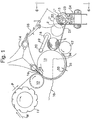
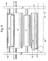
- the numeral 10 designates generally a frame for the machine which is seen in FIG. 6 to include side frames 10a and 10b.
- the side frames 10a and 10b rotatably support a plurality of rolls or drums for processing of a web and define essentially a winding path for the web in its travel from a parent roll (not shown) toward becoming a retail sized log of paper, other web material, foil, etc.
- a parent roll not shown
- a retail sized log of paper, other web material, foil, etc for additional details of winders, reference may be made to co-owned patents RE 28,353 and 4,828,195.
- the symbol W designates a web of material which is being advanced through a path designated in part by the symbol P and which first includes travel around a perforator roll 11 which operates against an anvil (not shown) to transversely perforate the web along equally longitudinal spaced lines of transverse perforation.
- a perforator roll 11 which operates against an anvil (not shown) to transversely perforate the web along equally longitudinal spaced lines of transverse perforation.
- the spacing between lines of perforation in toilet tissues may range in different parts of the world from 102 mm to 127 mm (4 to 5 inches). Different spacing are employed for kitchen toweling.
- a suitable perforator is seen in co-owned patent 2,870,840.
- lay-on roll designated 12 which again is suitably rotatably mounted like the other rolls or drums within the frames 10a and 10b.
- first winding drum or bedroll Positioned adjacent the lay-on roll 12 and still further in the path of travel of the web P is a first winding drum or bedroll generally designated 13.
- a mandrel-introducing mechanism generally designated 14.
- this is a hypocycloidal introducing mechanism of the nature shown in co-owned patent 4,856,725 which provides a gripping action on a cylindrical member.
- the mechanism 14 functions to introduce a mandrel such as designated 15 into the nip 16 between the lay-on roll 12 and the bedroll 13.
- a mandrel such as designated 15 into the nip 16 between the lay-on roll 12 and the bedroll 13.
- the mandrel 15 follows a portion of the winding path P inasmuch as the mandrel and the web are now proceeding together at least partway around the periphery of the first winding drum 13.
- the log L After the log L has been developed and a new mandrel is in the process of being wound, the log L rolls down a table 21 as indicated by the positions L', L'' and finally L'''.
- a stripping operation is performed wherein first the mandrel 15 which has an end protruding beyond the log L''' (FIG. 6) is gripped by means of a jaw gripper 22. Between the adjacent end of the log L''' and the gripper 22, a pusher 23 is interposed.
- the pushers 23 are carried by a conveyor mechanism generally designated 24 and operates to strip the log L''' from the mandrel 15 by moving the same axially along the mandrel 15 and onto an extended portion of the conveyor 24 (see FIG. 6).
- FIG. 1 shows the inventive winder using a very small diameter mandrel 15.
- the main objective of this winder is to produce a coreless roll with a very small hole in the center.
- the bedroll 13 uses vacuum port means generally designated 26 and 27 to hold the web against the bedroll surface.
- the vacuum port 26 is seen to include two separate arrangements of axially extending ports in the outer surface of the bedroll 13.
- the port means 26 include a triple row of primary vacuum ports 28 and a secondary double row of vacuum ports 29.
- the ports 29 are arranged to circumferentially flank the primary vacuum ports 28.
- the double row of vacuum ports 27 is spaced forwardly in the direction of rotation from the first mentioned vacuum port means 26.
- the main port means 26 is channeled to two separate vacuum supplies (not shown) so that the outer rows of vacuum ports 29 can be vented independently from the inner row 28.
- the inventive transfer uses an arcuate stationary plate to produce a pinch cutoff.
- This is analogous to the structure described in co-owned patent No. 4,828,195 except that the targeted perforation is isolated in part by means of vacuum ports 27.
- These ports 27 hold the tail T (FIG. 3) of the just-finished log on the bedroll 13 so that severing takes place between the ports 27 and the pinch point 30 developed by the coaction of the mandrel 15 and the arcuate stationary plate 31.
- the lay-on roll 12 is equipped with an annular groove 32 in its outer surface which accommodates the inlet end 31a of the stationary plate 31.
- the inlet end 31a has a surface 31b facing the bedroll drum 13 which is essentially tangent with the outer surface 12a of the lay-on drum 12.
- the pinching of the web causes a small amount of slack as at W 1 to be formed between the lay-on roll 12 and the mandrel 15.
- This slack web is immediately attracted to the bedroll 13 by the vacuum port means 26 and also directed to the bedroll 13 and away from the lay-on roll 12 by the centrifugal force of the web on the lay-on roll 12.
- the vacuum port means 26 then pull the slack web W 1 under the rolling mandrel 15.
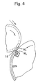
- FIG. 4 illustrates what happens in the enveloping of the mandrel 15 by the web a short time later than that depicted in FIG. 3.
- W 3 which is rearward in the direction of advance, i.e., upstream from the previously mentioned leading edge portion W 2 .
- This leading edge portion W 3 is now in the process of being folded under the mandrel 15 as at W 4 .
- W 5 the folded nature of the leading edge portion is seen more clearly and is designated W 5 .
- This folded edge W 5 is lifted and rolled by the rubbing action of the web leading edge portion W 2 moving over it.
- the vacuum port means 26 is arranged to enhance this tendency by allowing the web leading edge portion to expose the first row of ports 29a, hence allowing the vacuum therein as well as that in port 29b to decay prior to the vacuum in the ports 28. This, in turn, allows the web leading edge portion W 3 to be attracted to the bedroll 13 while the folded leading edge portion W 5 is being released. Once the folded leading edge portion W 5 is raised off of the bedroll 13, it is trapped inside of the web leading edge portion W 2 by virtue of the rolling of the mandrel 15.
- the geometry of the arcuate stationary plate 31 is arranged to allow for the rapid buildup diameter during the first part of the winding cycle.
- the gap 33 between the periphery of the bedroll 13 and the interior 31c of the stationary plate 31 gradually increases in proceeding from the upper inlet end where the mandrel 15 is being inserted until the outlet end 34 is reached.
- the new log reaches the outlet end 34, it rolls off of the plate 31 and proceeds to wind between the first or upper winding drum 13 and the second or lower winding drum 17.
- the remainder of the winding cycle generally follows that of a conventional surface winder in utilizing the rider roll 18, and inclined rolldown table 21.
- the next mandrel is inserted for transfer as the cycle repeats.
- the rider roll releases the finished log L''' which in turn rolls down an inclined exit table 21 to a roll strip conveyor generally designated 24.
- This conveyor is similar to the roll strip conveyor on co-owned patent 3,071,259.
- the gripper mechanism 22 lifts the mandrel 15 up onto the mandrel conveyor generally designated 35.
- One or more arms are provided along the length of the mandrel in order to help support the mandrel while it is being raised to the conveyor 35.
- the mandrel conveyor 35 then positions the mandrel to be received by the core inserter mechanism 14.
- Either side frame 10a, 10b is advantageously equipped with control means for regulating the various steps and actions described herein.
- advantages of the invention is the ability to operate a continuous running surface winder with recycled free mandrels and without the need for using adhesive or another means for adhering the web to the mandrel.
- a further advantage is the novel use of vacuum to hold both the feeding web and the web leading edge portion on the bedroll 13 to accomplish an enveloping transfer. This is further advantageous, again, in the elimination of adhesive or other means for maintaining the web in contact with the mandrel.
- the invention also is advantageous in that an extensible material such as rubber, plastic and the like can be used as the material for construction of the mandrel 15 so as to facilitate roll stripping.
- an extensible material such as rubber, plastic and the like
- longitudinal elongation caused by the stripping forces is accompanied by a reduction in radius.
- the relationship of the two depends upon Poisson's ratio.
- the compressive grip of the convolutely wound web on the mandrel is successfully reduced and overcome by the stripping force in combination with the elongation and reduction in radius.
- Another advantageous function of the invention is the opportunity of using porting on the bedrolls to isolate one specific line of perforation so as to give an exact sheet count.
- the use of the long stationary plate is advantageous to permit a significant build up in diameter of the log before rolling in to the three roll cradle winding nip.
Landscapes
- Moulding By Coating Moulds (AREA)
- Replacement Of Web Rolls (AREA)
- Winding Of Webs (AREA)
- Preliminary Treatment Of Fibers (AREA)
Claims (11)
- Bobineuse de surface comportant un bâti (10) procurant un passage d'enroulement (P) pour une bande (W) provenant d'un rouleau de départ vers un bloc sans mandrin de taille de distribution, un perforateur (11) sur ledit bâti (10) en premier dans ledit passage (P) afin de perforer ladite bande (W) transversalement le long de lignes longitudinalement espacées, un premier tambour d'enroulement (13) monté de façon rotative sur ledit bâti (10) afin de faire avancer en continu ladite bande (W) dans ledit passage (P) depuis ledit perforateur (11), ledit premier tambour d'enroulement (13) étant positionné sur un côté dudit passage (P), des moyens (14) sur ledit bâti (10) destinés à introduire de manière séquentielle des mandrins (15) dans ledit passage (P) pour contact avec ladite bande (W), un deuxième tambour d'enroulement (17) sur ledit bâti (10) de l'autre côté dudit passage (P) pour coopération avec ledit premier tambour d'enroulement (13) afin de développer un bloc enroulé de ladite bande (W), et des moyens (22 à 24) sur ledit bâti (10) destinés à extraire de manière séquentielle chaque mandrin (15) de son bloc associé, caractérisée par une plaque fixe courbe (31) sur ledit bâti (10) qui s'étend partiellement autour dudit premier tambour d'enroulement (13) sur ledit autre côté dudit passage (P) afin de coopérer avec ledit premier tambour d'enroulement (13), un mandrin (15) roulant sur ladite plaque courbe (31) du fait du mouvement transmis par le premier tambour d'enroulement (13) étant enveloppé avec ladite bande (W), chaque mandrin (15) ayant un diamètre tel qu'il forme un petit trou dans ledit bloc bobiné, et des moyens (35) associés de manière opérationnelle audit bâti (10) afin de recycler lesdits mandrins (15) desdits moyens d'extraction (22 à 24) vers lesdits moyens d'introduction (14).
- Bobineuse de surface selon la revendication 1, caractérisée par des moyens (26, 27) associés de manière opérationnelle audit premier tambour d'enroulement (13) afin de coopérer avec lesdits moyens de plaque courbe (31) et ledit mandrin qui roule (15) afin de séparer ladite bande (W) le long d'une ligne de perforations visée.
- Bobineuse de surface selon la revendication 2, caractérisée par des moyens d'orifice à dépression (27 à 29) qui constituent lesdits moyens associés de manière opérationnelle.
- Bobineuse de surface selon la revendication 1, caractérisée par un tambour fou (18) monté sur ledit bâti (10), lesdits premier tambour d'enroulement, deuxième tambour d'enroulement et tambour fou (13, 17, 18) étant montés de façon rotative dans ledit bâti (10) et disposés dans un berceau à trois tambours avec un étranglement entre lesdits premier et deuxième tambours d'enroulement (13, 17), lesdits moyens de plaque courbe (31) étant une plaque fixe qui s'étend partiellement autour dudit premier tambour d'enroulement (13) et ayant une entrée (16) et une extrémité de sortie (34), lesdits moyens d'introduction de mandrin (14) fonctionnant afin d'introduire un mandrin (15) dans ladite extrémité d'entrée (16), ladite extrémité de sortie (34) étant positionnée de façon adjacente au dit étranglement et étant davantage espacée dudit premier tambour d'enroulement (13) que ladite extrémité d'entrée (16) qui est espacée dudit premier tambour d'enroulement (13) afin de recevoir la bande (W) accumulée sur ledit mandrin (15).
- Bobineuse de surface selon la revendication 4, caractérisée par ledit premier tambour d'enroulement (13) qui est équipé de moyens d'orifices à dépression s'étendant axialement (26) dans sa surface, et de moyens de commande destinés à corréler la rotation dudit premier tambour d'enroulement (13) avec les moyens (14) destinés à introduire un mandrin (15) dans ladite extrémité d'entrée (16) lorsque lesdits moyens d'orifices à dépression (26) sont adjacents à ladite extrémité d'entrée (16).
- Bobineuse de surface selon la revendication 5, caractérisée par ledit premier tambour d'enroulement (13) qui est équipé de seconds moyens d'orifices à dépression s'étendant axialement (27) espacés circonférentiellement vers l'avant dans le sens de rotation du premier tambour d'enroulement (13) par rapport aux dits moyens d'orifices à dépression (26) mentionnés en premier, lesdits seconds moyens d'orifices à dépression (27) coopérant avec un mandrin (15) au niveau de ladite extrémité d'entrée (16) afin de mettre sous tension ladite bande (W) entre eux de façon à pincer ladite bande (W) le long d'une ligne de perforations.
- Bobineuse de surface selon la revendication 5, caractérisée par lesdits moyens d'orifices à dépression (26) qui comprennent des moyens d'orifices à dépression principaux et secondaires (28, 29), lesdits moyens d'orifices à dépression principaux (28) étant flanqués circonférentiellement par lesdits moyens d'orifices à dépression secondaires (29) afin de libérer de manière séquentielle une force sur la partie de bord avant (W2) d'une bande coupée (W) avant d'envelopper un mandrin (15).
- Bobineuse de surface selon la revendication 1, caractérisée par chaque mandrin (15) qui a un diamètre destiné à former un trou dans ledit bloc d'un diamètre dans la plage d'environ 10 mm à environ 20 mm (environ 0,375 pouce à environ 0,750 pouce).
- Procédé de bobinage d'une bande (W) dans un bloc enroulé sans mandrin comportant les étapes consistant à prévoir un bâti (10) définissant un passage d'enroulement (P) depuis un rouleau de départ vers un bloc sans mandrin de taille de distribution, équiper ledit bâti (10) d'un perforateur (11) en premier dans ledit passage (P) afin de perforer ladite bande (W) transversalement le long de lignes longitudinalement espacées, équiper ledit bâti (10) d'un premier tambour d'enroulement rotatif (13) sur un côté dudit passage (P) et équiper également ledit bâti (10) de moyens (14) destinés à introduire de manière séquentielle des mandrins (15) dans ledit passage (P), avancer en continu ladite bande (W) dans ledit passage (P) depuis ledit perforateur (11) en contact avec ledit premier tambour d'enroulement (13) et un mandrin (15), prévoir un deuxième tambour d'enroulement (17) sur ledit bâti (10) de l'autre côté dudit passage (P) pour coopération avec ledit premier tambour d'enroulement (13) afin de développer un bloc enroulé de ladite bande (W), et prévoir des moyens (22 à 24) sur ledit bâti (10) destinés à extraire de manière séquentielle chaque mandrin (15) de son bloc associé, caractérisé par le fait de prévoir une plaque courbe (31) sur ledit bâti (10) qui s'étend partiellement autour dudit premier tambour d'enroulement (13) sur ledit autre côté dudit passage (P) ; prévoir chaque mandrin (15) ayant un diamètre tel qu'il forme un petit trou dans ledit bloc bobiné ; faire coopérer ladite plaque courbe (31), ledit premier tambour d'enroulement (13) et un mandrin (15) roulant sur ladite plaque courbe (31) du fait du mouvement transmis par le premier tambour d'enroulement (13) afin d'envelopper ledit mandrin qui roule (15) avec ladite bande (W) ; et prévoir des moyens (35) associés de manière opérationnelle audit bâti (10) afin de recycler lesdits mandrins (15) desdits moyens d'extraction (22 à 24) vers lesdits moyens d'introduction (14).
- Procédé selon la revendication 9, caractérisé par le fait de prévoir chaque mandrin (15) avec un diamètre tel qu'il forme un trou dans ledit bloc d'un diamètre dans la plage d'environ 10 mm à environ 20 mm (environ 0,375 pouce à environ 0,750 pouce).
- Procédé selon la revendication 9 ou la revendication 10, caractérisé par le fait de prévoir ledit premier tambour d'enroulement (13) avec des moyens d'orifices à dépression s'étendant axialement (26, 27) dans sa surface, corréler la rotation dudit premier tambour d'enroulement (13) avec l'introduction de chaque mandrin (15) dans ledit passage (P) lorsque lesdits moyens d'orifices à dépression (26, 27) sont adjacents au dit passage (P), mettre sous tension ladite bande (W) entre chaque mandrin (15) qui entre dans ledit passage (P) et lesdits moyens d'orifices à dépression (26, 27) de façon à pincer ladite bande (W) le long d'une ligne de perforations, et prévoir des moyens d'orifices principaux (28) et secondaires (29) dans les moyens d'orifice (26, 27) mentionnés en premier avec lesdits moyens d'orifices principaux (28) qui sont flanqués circonférentiellement par lesdits moyens d'orifices secondaires (29), et libérer de manière séquentielle la force de dépression sur la partie de bord avant (W2) d'une bande coupée (W) avant d'envelopper un mandrin (15).
Applications Claiming Priority (2)
| Application Number | Priority Date | Filing Date | Title |
|---|---|---|---|
| US93342 | 1993-07-19 | ||
| US08/093,342 US5421536A (en) | 1993-07-19 | 1993-07-19 | Surface winder with recycled mandrels and method |
Publications (3)
| Publication Number | Publication Date |
|---|---|
| EP0635444A2 EP0635444A2 (fr) | 1995-01-25 |
| EP0635444A3 EP0635444A3 (fr) | 1996-04-10 |
| EP0635444B1 true EP0635444B1 (fr) | 1998-06-03 |
Family
ID=22238405
Family Applications (1)
| Application Number | Title | Priority Date | Filing Date |
|---|---|---|---|
| EP94111192A Revoked EP0635444B1 (fr) | 1993-07-19 | 1994-07-18 | Bobineur de surface avec mandrins recyclés et méthode |
Country Status (9)
| Country | Link |
|---|---|
| US (1) | US5421536A (fr) |
| EP (1) | EP0635444B1 (fr) |
| JP (1) | JPH08192940A (fr) |
| AT (1) | ATE166853T1 (fr) |
| AU (1) | AU6745994A (fr) |
| BR (1) | BR9402827A (fr) |
| CA (1) | CA2127631A1 (fr) |
| DE (1) | DE69410706T2 (fr) |
| ZA (1) | ZA945187B (fr) |
Families Citing this family (44)
| Publication number | Priority date | Publication date | Assignee | Title |
|---|---|---|---|---|
| RU2128617C1 (ru) * | 1994-06-16 | 1999-04-10 | Фабио Перини С.П.А. | Перемоточный станок для образования рулона ленточного материала |
| US6439502B1 (en) | 1995-02-28 | 2002-08-27 | Kimberly-Clark Worldwide, Inc. | Dispenser for coreless rolls of products |
| US5620148A (en) | 1995-03-10 | 1997-04-15 | Kimberly-Clark Corporation | Methods of making indented coreless rolls |
| US5875985A (en) * | 1995-03-10 | 1999-03-02 | Kimberly-Clark Worldwide, Inc. | Indented coreless rolls and method of making the same |
| IT1278644B1 (it) * | 1995-04-14 | 1997-11-27 | Perini Fabio Spa | Macchina ribobinatrice per rotoli di materiale nastriforme, con controllo dell'introduzione dell'anima di avvolgimento |
| IT1286563B1 (it) * | 1996-03-05 | 1998-07-15 | Perini Fabio Spa | Macchina ribobinatrice incorporante un incollatore per i rotoli completati e relativo metodo di avvolgimento |
| KR20010021838A (ko) * | 1997-07-15 | 2001-03-15 | 알코아 인코포레이티드 | 연속적인 스트립 처리 공정에서의 스트립 고속 이송 방법및 장치 |
| US6092759A (en) | 1997-09-08 | 2000-07-25 | Kimberly-Clark Worldwide, Inc. | System for dispensing coreless rolls of product |
| US6092758A (en) * | 1997-09-08 | 2000-07-25 | Kimberly-Clark Worldwide, Inc. | Adapter and dispenser for coreless rolls of products |
| US6082664A (en) | 1997-11-20 | 2000-07-04 | Kimberly-Clark Worldwide, Inc. | Coreless roll product and adapter |
| USD428286S (en) * | 1998-05-29 | 2000-07-18 | Kimberly-Clark Worldwide | Dispenser adapter for coreless rolls of products |
| US6360985B1 (en) | 1998-05-29 | 2002-03-26 | Kimberly-Clark Worldwide, Inc. | Dispenser adapter for coreless rolls of products |
| US6138939A (en) | 1998-08-17 | 2000-10-31 | Kimberly Clark Worldwide, Inc. | Coreless adapter for dispensers of cored rolls of material |
| US6056229A (en) | 1998-12-03 | 2000-05-02 | Paper Converting Machine Co. | Surface winder with pinch cutoff |
| IT1307874B1 (it) | 1999-05-11 | 2001-11-19 | Perini Fabio Spa | Metodo e dispositivo per la produzione di rotoli di materialenastriforme senza anima di avvolgimento. |
| US6372064B1 (en) * | 1999-12-13 | 2002-04-16 | C. G. Bretting Manufacturing Company, Inc. | Tail sealer apparatus and method |
| US6659387B2 (en) | 2000-11-07 | 2003-12-09 | Paper Converting Machine Co. | Peripheral rewinding machine and method for producing logs of web material |
| US6595459B2 (en) | 2001-01-30 | 2003-07-22 | Kimberly-Clark Worldwide, Inc. | Apparatus and process for winding webbed material upon cores |
| US6729572B2 (en) | 2001-10-31 | 2004-05-04 | Kimberly-Clark Worldwide, Inc. | Mandrelless center/surface rewinder and winder |
| US8210462B2 (en) * | 2002-02-28 | 2012-07-03 | Kimberly-Clark Worldwide, Inc. | Center/surface rewinder and winder |
| US8042761B2 (en) * | 2002-02-28 | 2011-10-25 | Kimberly-Clark Worldwide, Inc. | Center/surface rewinder and winder |
| US7909282B2 (en) * | 2002-02-28 | 2011-03-22 | Kimberly-Clark Worldwide, Inc. | Center/surface rewinder and winder |
| US8757533B2 (en) * | 2002-02-28 | 2014-06-24 | Kimberly-Clark Worldwide, Inc. | Center/surface rewinder and winder |
| US7000864B2 (en) | 2002-06-10 | 2006-02-21 | The Procter & Gamble Company | Consumer product winding control and adjustment |
| US8535780B2 (en) | 2009-10-06 | 2013-09-17 | Kimberly-Clark Worldwide, Inc. | Coreless tissue rolls and method of making the same |
| US8714472B2 (en) | 2010-03-30 | 2014-05-06 | Kimberly-Clark Worldwide, Inc. | Winder registration and inspection system |
| US8364290B2 (en) | 2010-03-30 | 2013-01-29 | Kimberly-Clark Worldwide, Inc. | Asynchronous control of machine motion |
| US9901008B2 (en) | 2014-10-27 | 2018-02-20 | Ebullient, Inc. | Redundant heat sink module |
| US9901013B2 (en) | 2011-06-27 | 2018-02-20 | Ebullient, Inc. | Method of cooling series-connected heat sink modules |
| US9854714B2 (en) | 2011-06-27 | 2017-12-26 | Ebullient, Inc. | Method of absorbing sensible and latent heat with series-connected heat sinks |
| US9848509B2 (en) | 2011-06-27 | 2017-12-19 | Ebullient, Inc. | Heat sink module |
| US9832913B2 (en) | 2011-06-27 | 2017-11-28 | Ebullient, Inc. | Method of operating a cooling apparatus to provide stable two-phase flow |
| US9854715B2 (en) | 2011-06-27 | 2017-12-26 | Ebullient, Inc. | Flexible two-phase cooling system |
| US9284147B2 (en) | 2012-09-21 | 2016-03-15 | Paper Converting Machine Company | Method and apparatus for producing coreless rolls of paper |
| US9352921B2 (en) | 2014-03-26 | 2016-05-31 | Kimberly-Clark Worldwide, Inc. | Method and apparatus for applying adhesive to a moving web being wound into a roll |
| US9852963B2 (en) | 2014-10-27 | 2017-12-26 | Ebullient, Inc. | Microprocessor assembly adapted for fluid cooling |
| US10184699B2 (en) | 2014-10-27 | 2019-01-22 | Ebullient, Inc. | Fluid distribution unit for two-phase cooling system |
| US20160120059A1 (en) | 2014-10-27 | 2016-04-28 | Ebullient, Llc | Two-phase cooling system |
| US10919253B2 (en) * | 2015-03-25 | 2021-02-16 | Ravi Kumar | Quilling device |
| US10427902B2 (en) | 2016-03-04 | 2019-10-01 | The Procter & Gamble Company | Enhanced introductory portion for a surface winder |
| US10442649B2 (en) | 2016-03-04 | 2019-10-15 | The Procter & Gamble Company | Surface winder for producing logs of convolutely wound web materials |
| US10427903B2 (en) | 2016-03-04 | 2019-10-01 | The Procter & Gamble Company | Leading edge device for a surface winder |
| IT201900023415A1 (it) | 2019-12-11 | 2021-06-11 | Mura Emilia Rosa Lucia La | Un manufatto multi strato in carta tissue o simile, macchina e linea per la fabbricazione di tale manufatto e relativo metodo di produzione |
| IT202000007171A1 (it) | 2020-04-03 | 2021-10-03 | Perini Fabio Spa | Una confezione di mascherine protettive, un metodo e una macchina per la loro produzione |
Family Cites Families (16)
| Publication number | Priority date | Publication date | Assignee | Title |
|---|---|---|---|---|
| IT578371A (fr) * | 1957-08-30 | 1900-01-01 | ||
| US3071259A (en) * | 1959-09-04 | 1963-01-01 | Paper Converting Machine Co | Winder loader |
| US3148843A (en) * | 1959-10-09 | 1964-09-15 | Fmc Corp | Breaker bar for web rewinding machine |
| US3131880A (en) * | 1962-06-11 | 1964-05-05 | Murray D J Mfg Co | Web roll winder shaft stripper |
| US3179348A (en) * | 1962-09-17 | 1965-04-20 | Paper Converting Machine Co | Web-winding apparatus and method |
| FR1593631A (fr) * | 1968-11-06 | 1970-06-01 | ||
| US3718302A (en) * | 1971-01-29 | 1973-02-27 | Midland Ross Corp | Coil and mandrel separating machinery |
| US3823887A (en) * | 1971-12-23 | 1974-07-16 | D Gerstein | Device for forming lightweight paper into rolls without any core |
| IT1165998B (it) * | 1979-09-21 | 1987-04-29 | Fabio Perini | Dispositivo avvolgitore continuo per nastri di carta ed altro nella produzione di carta igienica e manufatti analoghi |
| US4723724A (en) * | 1985-04-17 | 1988-02-09 | Paper Converting Machine | Web winding machine and method |
| US4856725A (en) * | 1986-04-01 | 1989-08-15 | Paper Converting Machine Company | Web winding machine and method |
| US4783015A (en) * | 1986-08-27 | 1988-11-08 | Shimizu Machinery Co., Ltd. | Toilet paper roll and method of manufacture thereof |
| US4828195A (en) * | 1988-02-29 | 1989-05-09 | Paper Converting Machine Company | Surface winder and method |
| IT1233708B (it) * | 1989-07-11 | 1992-04-14 | Perini Navi Spa | Macchina ribobinatrice per la formazione di rotoli o bastoni, e metodo di avvolgimento |
| US5104055A (en) * | 1991-02-05 | 1992-04-14 | Paper Converting Machine Company | Apparatus and method for making convolutely wound logs |
| IT1262046B (it) * | 1993-03-24 | 1996-06-18 | Guglielmo Biagiotti | Macchina ribobinatrice per la formazione di rotoli di materiale nastriforme con mezzi per l'interruzione del materiale nastriforme e relativo metodo di avvolgimento. |
-
1993
- 1993-07-19 US US08/093,342 patent/US5421536A/en not_active Expired - Lifetime
-
1994
- 1994-07-08 CA CA002127631A patent/CA2127631A1/fr not_active Abandoned
- 1994-07-14 AU AU67459/94A patent/AU6745994A/en not_active Abandoned
- 1994-07-15 ZA ZA945187A patent/ZA945187B/xx unknown
- 1994-07-15 BR BR9402827A patent/BR9402827A/pt not_active Application Discontinuation
- 1994-07-18 EP EP94111192A patent/EP0635444B1/fr not_active Revoked
- 1994-07-18 DE DE69410706T patent/DE69410706T2/de not_active Expired - Fee Related
- 1994-07-18 AT AT94111192T patent/ATE166853T1/de not_active IP Right Cessation
- 1994-07-19 JP JP6189912A patent/JPH08192940A/ja active Pending
Also Published As
| Publication number | Publication date |
|---|---|
| CA2127631A1 (fr) | 1995-01-20 |
| JPH08192940A (ja) | 1996-07-30 |
| DE69410706D1 (de) | 1998-07-09 |
| ZA945187B (en) | 1995-03-10 |
| ATE166853T1 (de) | 1998-06-15 |
| EP0635444A3 (fr) | 1996-04-10 |
| BR9402827A (pt) | 1995-08-22 |
| DE69410706T2 (de) | 1998-10-01 |
| US5421536A (en) | 1995-06-06 |
| EP0635444A2 (fr) | 1995-01-25 |
| AU6745994A (en) | 1995-01-27 |
Similar Documents
| Publication | Publication Date | Title |
|---|---|---|
| EP0635444B1 (fr) | Bobineur de surface avec mandrins recyclés et méthode | |
| EP1006066B1 (fr) | Enrouleur de surface avec dispositif de coupe par pincement | |
| EP1150912B1 (fr) | Ensemble coupe transfert pour enrouleur de bande | |
| RU2567202C2 (ru) | Машина для перемотки и способ производства рулонов из рулонного материала | |
| EP0695713B1 (fr) | Méthode et appareil pour enbobiner des bobines sans noyau | |
| US4487377A (en) | Web winding apparatus and method | |
| US4909452A (en) | Surface winder and method | |
| US8215086B2 (en) | Method and device for manufacturing rolls of web material with an outer wrapping | |
| GB2105688A (en) | Snap-separating of web material during transfer of winding onto new core | |
| IL166092A (en) | Rewinding machine for producing logs of wound web material and relative method | |
| US6659387B2 (en) | Peripheral rewinding machine and method for producing logs of web material | |
| EP0616965B1 (fr) | Procédé pour enrouler de bobines sans noyau | |
| EP0505712A1 (fr) | Dispositif et méthode d'enroulement par entraînement de contact | |
| CA2357336A1 (fr) | Rebobineuse peripherique et methode de production de mandrins de voile | |
| CA1265492A (fr) | Mecanisme et methode de bobinage de tissu | |
| JPS61124460A (ja) | 自動巻取り切替え装置 | |
| MXPA99011172A (en) | Surface winder with pinch cutoff | |
| JPH0539150A (ja) | ウエブ巻取機および方法 |
Legal Events
| Date | Code | Title | Description |
|---|---|---|---|
| PUAI | Public reference made under article 153(3) epc to a published international application that has entered the european phase |
Free format text: ORIGINAL CODE: 0009012 |
|
| AK | Designated contracting states |
Kind code of ref document: A2 Designated state(s): AT BE CH DE FR GB IT LI SE |
|
| PUAL | Search report despatched |
Free format text: ORIGINAL CODE: 0009013 |
|
| RHK1 | Main classification (correction) |
Ipc: B65H 19/22 |
|
| AK | Designated contracting states |
Kind code of ref document: A3 Designated state(s): AT BE CH DE FR GB IT LI SE |
|
| 17P | Request for examination filed |
Effective date: 19960912 |
|
| 17Q | First examination report despatched |
Effective date: 19961018 |
|
| GRAG | Despatch of communication of intention to grant |
Free format text: ORIGINAL CODE: EPIDOS AGRA |
|
| GRAG | Despatch of communication of intention to grant |
Free format text: ORIGINAL CODE: EPIDOS AGRA |
|
| GRAH | Despatch of communication of intention to grant a patent |
Free format text: ORIGINAL CODE: EPIDOS IGRA |
|
| GRAH | Despatch of communication of intention to grant a patent |
Free format text: ORIGINAL CODE: EPIDOS IGRA |
|
| GRAA | (expected) grant |
Free format text: ORIGINAL CODE: 0009210 |
|
| AK | Designated contracting states |
Kind code of ref document: B1 Designated state(s): AT BE CH DE FR GB IT LI SE |
|
| PG25 | Lapsed in a contracting state [announced via postgrant information from national office to epo] |
Ref country code: LI Free format text: LAPSE BECAUSE OF FAILURE TO SUBMIT A TRANSLATION OF THE DESCRIPTION OR TO PAY THE FEE WITHIN THE PRESCRIBED TIME-LIMIT Effective date: 19980603 Ref country code: CH Free format text: LAPSE BECAUSE OF FAILURE TO SUBMIT A TRANSLATION OF THE DESCRIPTION OR TO PAY THE FEE WITHIN THE PRESCRIBED TIME-LIMIT Effective date: 19980603 Ref country code: BE Free format text: LAPSE BECAUSE OF FAILURE TO SUBMIT A TRANSLATION OF THE DESCRIPTION OR TO PAY THE FEE WITHIN THE PRESCRIBED TIME-LIMIT Effective date: 19980603 Ref country code: AT Free format text: LAPSE BECAUSE OF FAILURE TO SUBMIT A TRANSLATION OF THE DESCRIPTION OR TO PAY THE FEE WITHIN THE PRESCRIBED TIME-LIMIT Effective date: 19980603 |
|
| REF | Corresponds to: |
Ref document number: 166853 Country of ref document: AT Date of ref document: 19980615 Kind code of ref document: T |
|
| REG | Reference to a national code |
Ref country code: CH Ref legal event code: EP |
|
| REF | Corresponds to: |
Ref document number: 69410706 Country of ref document: DE Date of ref document: 19980709 |
|
| ITF | It: translation for a ep patent filed | ||
| ET | Fr: translation filed | ||
| REG | Reference to a national code |
Ref country code: CH Ref legal event code: PL |
|
| PLBQ | Unpublished change to opponent data |
Free format text: ORIGINAL CODE: EPIDOS OPPO |
|
| PLBI | Opposition filed |
Free format text: ORIGINAL CODE: 0009260 |
|
| PLBF | Reply of patent proprietor to notice(s) of opposition |
Free format text: ORIGINAL CODE: EPIDOS OBSO |
|
| 26 | Opposition filed |
Opponent name: FABIO PERINI S.P.A Effective date: 19990225 |
|
| PGFP | Annual fee paid to national office [announced via postgrant information from national office to epo] |
Ref country code: GB Payment date: 19990617 Year of fee payment: 6 |
|
| PGFP | Annual fee paid to national office [announced via postgrant information from national office to epo] |
Ref country code: FR Payment date: 19990630 Year of fee payment: 6 |
|
| PGFP | Annual fee paid to national office [announced via postgrant information from national office to epo] |
Ref country code: SE Payment date: 19990705 Year of fee payment: 6 Ref country code: DE Payment date: 19990705 Year of fee payment: 6 |
|
| PLBF | Reply of patent proprietor to notice(s) of opposition |
Free format text: ORIGINAL CODE: EPIDOS OBSO |
|
| PLBF | Reply of patent proprietor to notice(s) of opposition |
Free format text: ORIGINAL CODE: EPIDOS OBSO |
|
| PG25 | Lapsed in a contracting state [announced via postgrant information from national office to epo] |
Ref country code: GB Free format text: LAPSE BECAUSE OF NON-PAYMENT OF DUE FEES Effective date: 20000718 |
|
| PG25 | Lapsed in a contracting state [announced via postgrant information from national office to epo] |
Ref country code: SE Free format text: LAPSE BECAUSE OF NON-PAYMENT OF DUE FEES Effective date: 20000719 |
|
| GBPC | Gb: european patent ceased through non-payment of renewal fee |
Effective date: 20000718 |
|
| EUG | Se: european patent has lapsed |
Ref document number: 94111192.4 |
|
| RDAH | Patent revoked |
Free format text: ORIGINAL CODE: EPIDOS REVO |
|
| PG25 | Lapsed in a contracting state [announced via postgrant information from national office to epo] |
Ref country code: FR Free format text: LAPSE BECAUSE OF NON-PAYMENT OF DUE FEES Effective date: 20010330 |
|
| REG | Reference to a national code |
Ref country code: FR Ref legal event code: ST |
|
| RDAG | Patent revoked |
Free format text: ORIGINAL CODE: 0009271 |
|
| STAA | Information on the status of an ep patent application or granted ep patent |
Free format text: STATUS: PATENT REVOKED |
|
| 27W | Patent revoked |
Effective date: 20010413 |