EP0635593A1 - Verfahren und Vorrichtung zum Verbinden von den zwei Rändern eines Schlaugartig gestrickten Produkts während seiner Herstellung - Google Patents
Verfahren und Vorrichtung zum Verbinden von den zwei Rändern eines Schlaugartig gestrickten Produkts während seiner Herstellung Download PDFInfo
- Publication number
- EP0635593A1 EP0635593A1 EP94830348A EP94830348A EP0635593A1 EP 0635593 A1 EP0635593 A1 EP 0635593A1 EP 94830348 A EP94830348 A EP 94830348A EP 94830348 A EP94830348 A EP 94830348A EP 0635593 A1 EP0635593 A1 EP 0635593A1
- Authority
- EP
- European Patent Office
- Prior art keywords
- remeshing
- row
- manufactured product
- needles
- needle
- Prior art date
- Legal status (The legal status is an assumption and is not a legal conclusion. Google has not performed a legal analysis and makes no representation as to the accuracy of the status listed.)
- Granted
Links
Images














Classifications
-
- D—TEXTILES; PAPER
- D04—BRAIDING; LACE-MAKING; KNITTING; TRIMMINGS; NON-WOVEN FABRICS
- D04B—KNITTING
- D04B15/00—Details of, or auxiliary devices incorporated in, weft knitting machines, restricted to machines of this kind
- D04B15/02—Loop-transfer points
-
- D—TEXTILES; PAPER
- D04—BRAIDING; LACE-MAKING; KNITTING; TRIMMINGS; NON-WOVEN FABRICS
- D04B—KNITTING
- D04B15/00—Details of, or auxiliary devices incorporated in, weft knitting machines, restricted to machines of this kind
- D04B15/18—Dials
-
- D—TEXTILES; PAPER
- D04—BRAIDING; LACE-MAKING; KNITTING; TRIMMINGS; NON-WOVEN FABRICS
- D04B—KNITTING
- D04B35/00—Details of, or auxiliary devices incorporated in, knitting machines, not otherwise provided for
- D04B35/02—Knitting tools or instruments not provided for in group D04B15/00 or D04B27/00
- D04B35/04—Latch needles
-
- D—TEXTILES; PAPER
- D04—BRAIDING; LACE-MAKING; KNITTING; TRIMMINGS; NON-WOVEN FABRICS
- D04B—KNITTING
- D04B9/00—Circular knitting machines with independently-movable needles
- D04B9/40—Circular knitting machines with independently-movable needles with provision for transfer of knitted goods from one machine to another
Definitions
- the present invention relates to a method and a device for effecting the union of two edges of a knitted tubular manufactured product, such as for example the remeshing of the tips of the stockings, at the end of the knitting of the manufactured product.
- the Italian patent application Nr. FI92A194 describes a method for effecting the union of the two front edges of a knitted tubular manufactured product, especially a stocking and comprising the phase of manufacturing a knitted tubular manufactured product, with a circular machine with a cylinder.
- the process of which also comprises the following operational phases: - lifting a predetermined number of needles from a first half-row with the respective adjacent meshes up to a predetermined level: by half-row being understood a plurality of adjacent meshes and which belong to an edge of the tip of the manufactured product; - raise a predetermined number of needles in a second half-row with the respective stitches, and bring them to the same level as those in the first half-row; - take the stitches from the first half-row, lower the corresponding needles and transfer them with a 180 ° turn around a diametrical horizontal axis of the needle cylinder, so that each stitch thus inverted engages the needle second row correspondent; - free the stitches of the first half-row from the respective transfer means and arrange the pairs of stitches as well superimposed on a level useful for their remeshing; - turn the needle cylinder with an intermittent movement and insert a remeshing needle into a pair of
- a device for implementing said method which comprises: - cam means for the vertical movement of a number of predetermined needles of a first and of a second half-row of stitches of the tip of the manufactured product in manufacture, which means are in the active condition when the knitting cams of the circular machine are in the inactive condition and reverse; - Means for removing the stitches from said first half-row and turning them 180 ° around a horizontal diametral axis of the needle cylinder, with a pair of staples for each stitch and at least one corresponding latch, opening and closing respectively, each of which is slidably housed in a corresponding recess in a semi-circular sector: said sector being mounted rotating with angular amplitude of 180 ° in both directions around a horizontal diametrical axis of the needle cylinder, in position located above the machine plates; means for making said semi-circular sector integral with the cylinder to needles, with a radial shutter sliding between two positions, blocking and respectively unlocking the sector relative to the needle
- the above-mentioned process even if it makes it possible to produce a finished finished product of good quality, includes the necessity of leaving the knitting needles inserted, which support the stitches of the manufactured product during the remeshing phase, inside the loops which constitute the stitches, as well as the union line of the edges of the manufactured product results slightly dilated.
- the stitching pitch of the aforementioned edges is equal to that of knitting, rather than inferior, as on the other hand it is necessary to obtain a tighter and elastic seam and thus to produce a product of better quality.
- the device for carrying out this previously known process has a very complex construction, especially in relation to the large number of elements placed in correspondence with the textile head of the circular machine.
- the circular machines for the basic knitting of the manufactured product must be suitably adapted, under the architectural profile, under the structural mechanical profile and finally under the functional profile, for the specific arrangement of the means adopted for carry out the above method of closing the point.
- this represents a penalty due to the limitation of the degree of interchangeability of the device which, therefore, must be designed in relation to the specific knitting machine for which it is intended.
- the main aim of the present invention is that of eliminating the drawbacks which derive from traditional operational methodologies and of proposing a method and an automatic device for joining two edges of a knitted tubular manufactured product which make it possible to obtain a finished manufactured product of superior quality and at the same time, to achieve a great functional simplification as regards the manufacture and handling of the device for remeshing and of the machine for knitting.
- a stitch is heard in the retained position when it, engaged on a needle valve, is found at a level between the staple of the needle and the free end of the valve in a completely opened.
- it is planned to insert the final part of the remeshing wire inside the manufactured product, after the execution of the closing nodes of the chain.
- the remeshing wire can be the same used for knitting the manufactured product, with no continuity, like a different yarn, fed by a corresponding spool, separated from that of the knitting yarn.
- means are provided for inserting the final part of the remeshing wire which results, connected to the manufactured product, inside the latter.
- the advantages obtained thanks to the present invention essentially consist in the fact that it is possible to effect the closure of the tip of a knitted tubular manufactured product, on the same machine which produces them, thus obtaining a great reduction in the time and cost of manufacture; which are completely eliminated from certain phases of the traditional process of closing the tip of knitted tubular manufactured products, such as for example the formation of the throwing discard and the corresponding waste, the transfer of the manufactured products from the circular machine to the storage stores or to the machines sewing or remeshing, turning them over, sewing the point and successive straightening; that it is possible to automatically remesh the edges of the manufactured product outside the knitting station and place the remeshing means at a predetermined distance from the latter, while producing a single productive unit; that it is possible to obtain a high degree of accessibility to the means of the knitting station and to those of the remeshing station, as also to the means
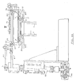
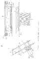
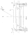
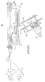
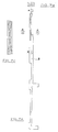
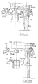
- FIG. 1A shows, schematically, in longitudinal section, a device according to a first embodiment of the invention, in the position of beginning of the closing cycle of the tip of the tubular manufactured product
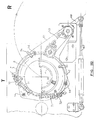
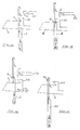
- Fig. 1B represents the plan view of the means for transferring the manufactured product from the knitting statin to that of remeshing, in the device of FIG. 1A
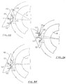
- Fig. 1C shows the detail of the cams and of the respective control means for producing the reversal of the semi-circular sector of the device of FIG.
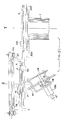
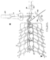
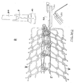
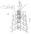
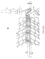
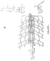
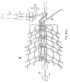
- Fig. 2A schematically represents the means of FIG. 1B, with the remeshing means in the waiting condition
- Fig. 2B shows the means of FIG. 1B in the position for detaching the textile head from the machine, with the remeshing means in the standby condition
- Fig. 2C shows the means of FIG. 1B in the position of remeshing the tip of the manufactured product, with the remeshing means in the active condition
- Fig. 2D schematically represents the phase of FIG. 2A with the suction tube of the textile machine in the normal position, that is to say lowered
- Fig. 2E represents the phase of FIG. 2B with the suction tube in the raised position
- Fig. 2A schematically represents the means of FIG. 1B, with the remeshing means in the waiting condition
- Fig. 2B shows the means of FIG. 1B in the position for detaching the textile head from the machine, with the
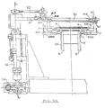
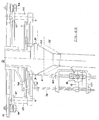
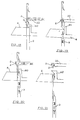
- FIG. 3A shows the side view of a device as in FIG. 1A, according to an alternative embodiment
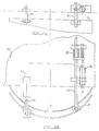
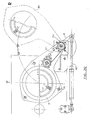
- Fig. 3B represents the plan view of the oscillating semi-circular sector, of the relative support member, of the corresponding turning-over means and of the means for locking the housing of the plates fixed in space
- Fig. 3C shows a plan view of the means for transferring the manufactured product from the knitting station to the remeshing station in the device of FIG. 3A
- Fig. 3D represents the detail of the means of joining the case of the plates with the machine, in the start phase of the respective movement
- Fig. 3E shows the detail of the means of FIG. 3D and 3E in the initial phase of the respective movement, that is to say to return to the initial position
- Fig. 3B represents the plan view of the oscillating semi-circular sector, of the relative support member, of the corresponding turning-over means and of the means for locking the housing of the plates fixed in space
- Fig. 3C shows a plan view of the means for transferring
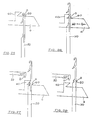
- FIG. 4 schematically represents a partial longitudinal section of the needle cylinder of a machine with a device according to the invention, in the phase of turning over the oscillating sector for the transfer of the stitches of the first half-row onto the needles of the second half row;
- Fig. 5 shows the means of FIG. 3C, partial longitudinal section, in a machine with a device according to the invention and with the means of FIG. 3C in the raised oscillating sector position of the textile head, with the respective control means and with the needle positioning means;
- Fig. 6A shows, in partial longitudinal section, the station for re-molding the tip of the manufactured product, with the means of FIG. 3C in the remeshing phase;
- Fig. 5 shows the means of FIG. 3C, partial longitudinal section, in a machine with a device according to the invention and with the means of FIG. 3C in the raised oscillating sector position of the textile head, with the respective control means and with the needle positioning means;
- Fig. 6A shows, in partial longitudinal section, the station
- FIG. 6B represents the detail of the remeshing phase of the tip of the manufactured product, according to an alternative embodiment
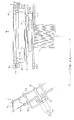
- Fig. 6C shows the detail of a sewing machine with a sliding needle for carrying out the remeshing
- Fig. 6D shows the plan view of the detail of FIG. 6C
- Fig. 6E shows the front view of the needle bar, with the relative auxiliary members, of the sewing machine of FIG. 6C
- Fig. 6F represents, in partial section, the detail of the remeshing needle, with the clamping slide of the respective staple
- Fig. 7A shows the side view of a needle of the knitting cylinder of the circular machine
- Fig. 7B represents the section along AA in FIG. 7A
- Fig. 7C represents the section along XX of FIG.
- Fig. 8A shows the plan view of a staple for picking up and turning over meshes, with the head oriented to the right;
- Fig. 8B shows the side view of the staple of FIG. 8A;
- Fig. 9A shows the plan view of the staple complementary to that of FIG. 8A, that is to say with the head oriented to the left;
- Fig. 9B shows the side view of the staple of FIG. 9A;
- Fig. 10A shows the plan view of the clamping bolt associated with the staple of FIG. 8A;
- Fig. 10B shows the side view of the bolt of FIG. 10A;
- Fig. 11A shows the plan view of the clamping bolt associated with the staple of FIG. 9A;
- Fig. 11B shows the side view of the bolt of FIG. 11A;
- FIG. 12A shows the plan view of the assembly of the two staples and the corresponding bolts in the open position
- Fig. 12B represents the section along CC of FIG. 12A
- Fig. 13A shows the plan view of the assembly of the two staples and the corresponding bolts in the clamping position
- Fig. 13B represents the section following DD of FIG. 13A
- Fig. 14 shows a needle of the first half-row in the initial phase of the closing cycle of the tip of the manufactured product
- Fig. 15 shows the needle of FIG. 14 in the ascent phase, with the plates closed
- Fig. 16 shows the needle of FIG. 14 in an intermediate phase of its ascent race, with the plates open
- FIG. 17 represents the detail of a needle of the second half-row in the terminal phase of its first ascent;
- Fig. 18 shows the needle of FIG. 16, where he sees one of the respective staples in the phase of approximation to the corresponding mesh;
- Fig. 19 shows the needle of FIG. 18, with the staple in the mesh attachment phase;
- FIG: 20 represents the needle of FIG. 18, with the staple in the mesh removal phase;
- Fig. 21 represents the needle of FIG. 18 in the lowered position;
- Fig. 22 shows the detail of a needle of the second half-row, or one of the respective staples is visible, in the interception phase of the corresponding stitch of the first half-row which has been transferred;
- Fig. 23 shows the needle of FIG.
- FIG. 24 shows the needle of FIG. 23 in the ascent position to release the corresponding mesh from the first half-row of the staple
- Fig. 25 shows the needle of FIG. 24 in the lowered position below the spout of the plates, with the corresponding meshes of the first and second half-rows in the retained position and with the respective open plate
- Fig. 26 shows the needle of FIG. 25 in the ascent phase, with the stage closed
- Fig. 27 shows the needle of FIG. 26 in another ascent phase, with the plates closed
- Fig. 28 shows the needle of FIG. 27 in another ascent phase and with the respective open stage
- Fig. 29 shows the needle of FIG.
- FIG. 30 shows the needle of FIG. 29 during the final ascent phase to agree to the removal of the corresponding meshes by the staple
- Fig. 31 shows the needle of FIG. 30 in the descent phase
- Fig. 32 shows the needle of FIG. 31 in the final descent phase, with the corresponding meshes of the first and second half-rows which have been taken up by the staple
- Fig. 33A shows the needle of FIG. 23 in the ascent phase, with the corresponding mesh of the first half-row in the retained position and with the mesh of the second half-row blocked by the corresponding staple, according to an alternative embodiment of the present device
- Fig. 33B shows the needle of FIG.
- FIG. 33A in the final descent phase, with the corresponding stitch of the second half-row which has been unloaded
- Fig. 33C shows the needle of FIG. 33B during the final ascent phase, with the plates closed which block the corresponding mesh of the first half-row loaded on the rod
- Fig. 33D represents the needle of FIG. 33C in the phase of another ascent, with the plates open and with the corresponding staple in the phase of approximation to the corresponding mesh of the first half-row
- Fig. 33E represents the needle of FIG. 33D, with the staple in the approach phase
- Fig. 33F represents the needle of FIG. 33E during the final ascent phase to allow the removal of the corresponding mesh from the first half-row by the respective staple
- Fig. 33G represents the needle of FIG.
- Fig. 33F in the descent phase
- Fig. 33H represents the needle of FIG. 33G in the final descent phase, and the corresponding stitch of the first half row which has been taken up by the respective staples
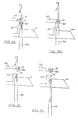
- Fig. 34A represents the detail of the phase of formation of the closing nodes of the chain, at the end of the remeshing of the tip of the manufactured product
- Fig. 34B represents the detail of the sampling phase of the end part of the re-molding wire, by the means of insertion of the latter inside the tip of the manufactured product, before making the cut
- Fig. 34C shows the detail of the phase of placement in the operational position of the cutting and movement means of said wire insertion means itself
- Fig. 35 shows the detail in the phase of FIG. 34C, according to an alternative embodiment
- Fig. 34A represents the detail of the phase of formation of the closing nodes of the chain, at the end of the remeshing of the tip of the manufactured product
- Fig. 34B represents the detail of the sampling phase of the end part of the
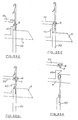
- FIG. 36 shows the detail of the phase of FIG. 34D, according to an alternative embodiment, after the phase of FIG. 35;
- Fig. 37 shows the detail of the PRESA predisposition phase of the remeshing wire, and of the operational means correspondents, according to an alternative embodiment;
- Fig. 38A shows the detail of the phase of positioning the means for cutting the molding wire and removing the terminal part of the wire, by means suitable for its insertion inside the manufactured product, after the phase of FIG. 37;
- Fig. 38B shows the detail of the cutting phase of the remeshing wire and of inserting the terminal part of the latter inside the manufactured product, after the phase of FIG. 38;
- Fig. 39A represents the phase of FIG. 38A, according to an alternative embodiment;
- Fig. 39B represents the phase of FIG.
- Fig. 40 schematically represents the phase of attachment of a portion of the manufactured product to facilitate the introduction of the means for attaching the remeshing wire and of inserting the latter inside the manufactured product;
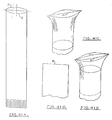
- Fig. 41A shows the perspective view of any tubular manufactured product with the tip open;
- Fig. 41B schematically represents the manufactured product of FIG. 41A in the prefinal phase of closing the tip;
- Fig. 41C schematically represents the manufactured product of FIG. 41A in the final phase of closing the point;
- Fig. 41D shows the view in longitudinal section of FIG. 41C;
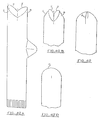
- Fig. 42A shows the perspective view of a bottom with the point formed by two identical and adjacent edges (S, R), called "fish mouth”;
- Fig. 40 schematically represents the phase of attachment of a portion of the manufactured product to facilitate the introduction of the means for attaching the remeshing wire and of inserting the latter inside the manufactured product;
- Fig. 41A shows the perspective view of any tubular manufactured product with the tip open;
- FIG. 42B schematically represents the bottom of FIG. 42A in the pre-final phase of closing the tip
- Fig. 42C schematically represents the bottom of FIG. 42A in the final phase of closing the point
- Fig. 42D represents the view in longitudinal section of FIG. 42C
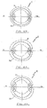
- 43 shows schematically the subdivision into two half-rows of a knitting cylinder with an even number of needles
- Fig. 44 shows, schematically, the subdivision into two half-rows of a knitting cylinder of a knitting cylinder with an odd number of needles
- Fig. 45 shows, schematically, another subdivision into two half-rows of a knitting cylinder
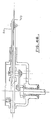
- Fig. 46 shows the detail of the means for the insertion of the terminal part of the molding wire inside the manufactured product
- Fig. 47 shows a machine according to the invention in the knitting position, with the plate near the needle cylinder
- Fig. 48 shows the machine of FIG. 46 with the plate away from the needle cylinder.
- the end of the transfer phase of the manufactured product from the knitting station (T) to that (R) of remeshing it is planned to position said means for taking off the meshes (8,80) at a useful level to allow movement by the corresponding control members, so as to place the meshes (8,80) in the desired position and to consent to their abandonment after remeshing.
- a downward air suction by means of a corresponding tube (92) coaxial with the manufactured product, so as to agree to relax it during its remeshing.
- a hook (14) and chain guide (10) to cooperate with the needle (9) the formation of the stitching points and of the chain closing nodes.
- said cams (7) have a basically helical profile.
- said sector (4) is provided with two rollers (41), which are mounted idly on corresponding horizontal shafts (42) on the opposite side with respect to the axis of symmetry (dd) of the sector (4), and they are intended to feel the active profile of said cams (7) to cause the sector (4) to overturn.
- a motor shaft with vertical axis for simplification not shown in the accompanying drawings, which performs its own rotational movement of the main transmission of the textile machine, the upper end of which is provided with a toothed pinion which must engage with a toothed crown (66) which is integrally connected to the crown (5).
- This allows the rotation of the crown (5) in the knitting station (T), in phase with the cylinder (1).
- each staple (2) is provided with two heels (21), which are prominent on the opposite side and vertically offset, to allow the alternative translation within the respective grooves of the sector (4) thanks to a corresponding cam ( 201) in the knitting stations (T) and cams (58) and (59) in the remeshing station (R).
- each bolt (20) is provided with two heels (22), protruding on the opposite side and vertically offset, to allow movement thereof in the direction of closing, respectively opening, of the corresponding staples (2) in the phase capture, respectively release, of the meshes (8,80) to be united.
- the height and the width of said heels (21, 22) are chosen in relation to the active profile of the corresponding control cam.
- the head of said staples (2) has a wedge-shaped profile, to facilitate the capture, respectively release, of the meshes (8,80).
- said staples (2) have the point folded in correspondence of the head, laterally and internally in the respective sliding direction to allow insertion into corresponding longitudinal cavities of the needles (3.30) and thus allow the capture of the meshes (8,80) of the first and the second half-row (x, y).
- the outer face of the point of each bolt (20) is contiguous, that is to say juxtaposed, with the inner face of the respective staple (2).
- each bolt (20) is provided with a transverse appendage (27) capable of forming a guide element relative to the point of the corresponding staple (2) and delimiting, in cooperation with a corresponding recess (28) of the relative staple (2), a seat (29) for the corresponding meshes (8,80) in the closed position.
- a transverse appendage (27) capable of forming a guide element relative to the point of the corresponding staple (2) and delimiting, in cooperation with a corresponding recess (28) of the relative staple (2), a seat (29) for the corresponding meshes (8,80) in the closed position.
- the means (95) for cutting the remeshing wire (F) are arranged in proximity to the working zone of the remeshing needle (9), on the same side of the remeshing machine (130) with respect to to the remeshing line.
- said cutting means (95) are arranged on the opposite side of the pruner (130) relative to the re-molding line.
- means are provided for inserting the final end of the stitching wire (F) inside the manufactured product, after the formation of the closure knots of the stitching itself, with a needle (93) with slide (94) , placed in front of the closing nodes and able to take the said wire (F) and insert it fully into the manufactured product, with a translational movement, and here abandon it.
- the wire (F) spontaneously comes out of the needle (93), by the effect of the retraction of the latter and prior opening of the slide.
- a needle (98) with slide (99) is placed on the opposite side of the remeshing needle (9) with respect to said closure nodes.
- the thread (F) is released spontaneously from the needle (98) by the effect of the retraction of the latter, prior tightening of the respective slide (99).
- means are provided for carrying out the elastic tension of the mesh of the manufactured product during the remeshing phase, with a suction tube (92) placed below the remeshing means and connected to the vacuum cleaner of the machine which produces the manufactured product. .
- the same tube (92) can be used to convey the finished manufactured products to the respective storage stores.
- the axis (aa) of rotation of the sector (4) is passing through two diametrically opposite needles of the cylinder (1), as well as the stitches of the first half-row removed result in an even number to that of the needles (3.30) of the cylinder (1) minus two, divided by two, and result displaced on as many needles (30) of the second half-row.
- the two stitches (80) of the two needles (30) which result at the ends of the second half-row and which have been excluded from the process of moving the meshes (8) of the first half-row, are also re-meshed.
- the axis (aa) of rotation of the sector (4) is passing between two pairs of diametrically opposite needles (3,30) of the cylinder (1). In this way, the number of stitches displaced results in even half the total number of needles (3.30).
- the axis (aa) of rotation of the sector (4) is passing in correspondence with a needle (30) of the second half-row and the middle line of the needles (3.30) placed at the ends of the respective half-rows.
- the stitches to be transferred correspond to the total number of needles minus one and divided by two, and the number of needles (30) in the second half row is equal to the number of needles (3) in the first half row plus one.
- the tray (37) it is planned to mount the yarn guide assembly (47,48) of the machine on a flange (43) linked to the column (45) of the plate (41) with a pawl (46) to activate / deactivate the junction.
- the lifting of the wire guide assembly (47, 48) is determined so as to allow the action of the means of removal and transfer of meshes (8,80).
- the cylinder (1) has just turned 180 ° relative to the sector (4) until the latter results in exact correspondence with the needles (30) of the second half-row.
- the cams (31) control the lifting of the needles (30), with the plates closed, until the corresponding meshes (8,80), retained by the plates (6) do not result in a predetermined position relative to the rod of the respective needles (30), that is to say in a position suitable for consenting their successive removal by the same staples (2) which have operated the displacement.
- the needles (30) come lifted up to bring the pair of meshes (8,80) up to the aforementioned staples (2) which, at this point, are advanced and are closed by the respective bolts (20), so as to capture the meshes ( 8.80).
- the needles (30) come down, and the manufactured product results with the pairs of stitches (8,80) retained by the staples (2) and thus freed from the needles (3,30).
- the crown (5) is raised, with the sector (4) and with the manufactured product retained by the staples (2), by means of the actuation of the cylinder (52). At this point, the suction tube (100) is raised.
- the actuation of the cylinder (67) determines the rotation of the column (52) around the axis (bb) and, integrally with it, of the crown (5), since it is supported by the arm (51 ) rigidly linked to the same column (52).
- the crown (5) is placed in correspondence with the remeshing station (R), and lowered to a useful level to allow the intervention of the cams (59) of movement of the staples (2) with the respective bolts (20) in the closed position.
- the needle (9) is inserted into a pair of corresponding stitches (8.80) forming a remeshing stitch in a simple chain.
- the needle (9) with the cooperation of the hook (14) and the chain guide (10), makes two or more knots of closure.
- the wire (F) comes captured by the needle (93), which has the slide open, and after the closure of the slide, the needle (93) is advanced towards the inside of the manufactured product and at the end, the wire (F) just cut. In this way, the final end of the remeshing wire (F) is inserted inside the manufactured product, by means of another advancement of the needle (93).
Landscapes
- Engineering & Computer Science (AREA)
- Textile Engineering (AREA)
- Knitting Machines (AREA)
- Treatment Of Fiber Materials (AREA)
- Sewing Machines And Sewing (AREA)
- Knitting Of Fabric (AREA)
- Socks And Pantyhose (AREA)
Applications Claiming Priority (2)
| Application Number | Priority Date | Filing Date | Title |
|---|---|---|---|
| ITFI930128 | 1993-07-12 | ||
| IT93FI000128A IT1265881B1 (it) | 1993-07-12 | 1993-07-12 | Metodo e dispositivo per eseguire l'unione di due lembi di un manufatto tubolare tessuto a maglia al termine della sua formazione |
Publications (2)
| Publication Number | Publication Date |
|---|---|
| EP0635593A1 true EP0635593A1 (de) | 1995-01-25 |
| EP0635593B1 EP0635593B1 (de) | 1997-10-15 |
Family
ID=11350526
Family Applications (1)
| Application Number | Title | Priority Date | Filing Date |
|---|---|---|---|
| EP94830348A Expired - Lifetime EP0635593B1 (de) | 1993-07-12 | 1994-07-11 | Verfahren und Vorrichtung zum Verbinden von den zwei Rändern eines schlauchartig gestrickten Produkts während seiner Herstellung |
Country Status (17)
| Country | Link |
|---|---|
| US (1) | US5487281A (de) |
| EP (1) | EP0635593B1 (de) |
| KR (1) | KR0136960B1 (de) |
| CN (1) | CN1062921C (de) |
| AT (1) | ATE159305T1 (de) |
| BR (1) | BR9402682A (de) |
| CA (1) | CA2127734C (de) |
| CZ (1) | CZ285739B6 (de) |
| DE (1) | DE69406206T2 (de) |
| ES (1) | ES2110207T3 (de) |
| IL (1) | IL110188A (de) |
| IT (1) | IT1265881B1 (de) |
| RU (1) | RU2114226C1 (de) |
| SK (1) | SK281557B6 (de) |
| TR (1) | TR27762A (de) |
| TW (1) | TW333565B (de) |
| UA (1) | UA41306C2 (de) |
Cited By (12)
| Publication number | Priority date | Publication date | Assignee | Title |
|---|---|---|---|---|
| EP0679746A3 (de) * | 1994-04-26 | 1995-12-06 | Sangiacomo S.p.A. | Vorrichtung zur Verarbeitung von gestrickten Produkten, welche an Strumpfrundstrickmaschinen hergestellt sind |
| EP0942086A2 (de) | 1998-02-20 | 1999-09-15 | FABRITEX S.r.l | Verfahren und Vorrichtung zum Vernähen der Ränder von Strickwaren |
| EP0875613A3 (de) * | 1997-04-30 | 1999-11-03 | MATEC S.r.l. | Rundstrickmaschine mit Vorrichtung zum Übertragen von auf Naden einer Nadelzylinderhälfte geformten Strickmaschen zu den Nadeln der anderen Nadelzylinderhälfte |
| WO2000001869A1 (en) * | 1998-07-07 | 2000-01-13 | Metalworking And Finance Group International S.A. | Method and device for closing the toe of a tubular article on a knitting machine |
| EP0924326A3 (de) * | 1997-12-04 | 2000-05-24 | FABRITEX S.r.l | Verfahren und Vorrichtung zur Herstellung von Schlauchwaren |
| EP1118700A1 (de) * | 2000-01-18 | 2001-07-25 | Metalworking And Finance Group International S.A. | Verfahren und Vorrichtung zur Herstellung von Schlauchstrickwaren und zum Schliessen des Zehenteils |
| FR2808813A1 (fr) * | 2000-05-12 | 2001-11-16 | Nakahira Tomotake | Procede et appareil pour coudre le bout d'une chaussette |
| WO2002070801A1 (en) * | 2001-03-08 | 2002-09-12 | Golden Lady S.P.A. | Device for picking up a tubular knitted article from a knitting machine and for sewing the toe |
| US7107797B2 (en) | 2002-10-21 | 2006-09-19 | Fabritex S.R.L | Method and apparatus for joining the edges of a tubular knitted article |
| WO2006137097A1 (en) * | 2005-06-23 | 2006-12-28 | Golden Lady Company S.P.A. | Method and device for orienting a tubular knitted article, such as a sock, angularly around an axis |
| EP2873761A1 (de) * | 2013-11-15 | 2015-05-20 | Da Kong Enterprise Co., Ltd. | Zungenzahn von Strumpfwaren-Stickmaschine |
| CN105463691A (zh) * | 2014-09-02 | 2016-04-06 | 上海腾成实业有限公司 | 新型高速立式羊毛衫缝合机自动转针装置 |
Families Citing this family (31)
| Publication number | Priority date | Publication date | Assignee | Title |
|---|---|---|---|---|
| IT1277395B1 (it) * | 1995-07-28 | 1997-11-10 | Matec Srl | Procedimento per la produzione di calze o simili a punta chiusa con una macchina circolare monocilindrica |
| IT1277396B1 (it) * | 1995-07-28 | 1997-11-10 | Matec Srl | Procedimento e dispositivo per eseguire l'unione di due lembi di un manufatto tubolare al termine della sua formazione particolarmente |
| IT1286604B1 (it) * | 1996-04-29 | 1998-07-15 | Golden Lady Spa | Metodo e dispositivo per la chiusura della punta all'inizio della fabbricazione di una calza o calzino,in una macchina da maglieria |
| IT1289504B1 (it) * | 1996-12-20 | 1998-10-15 | Lonati Spa | Procedimento per la produzione di manufatti tubolari,del tipo calze o simili,con una macchina circolare monocilindrica |
| IT1314899B1 (it) * | 2000-06-27 | 2003-01-16 | Sangiacomo Spa | Dispositivo di sollevamento del manufatto a maglia costruito su unamacchina circolare. |
| ITFI20010143A1 (it) | 2001-07-24 | 2003-01-24 | Fabritex Srl | Metodo e dispositivo per manipolare o movimentare le maglie di un manufatto tessile |
| JP2004033443A (ja) * | 2002-07-02 | 2004-02-05 | Dan:Kk | 縫製方法 |
| ITMI20022442A1 (it) * | 2002-11-18 | 2004-05-19 | Exacta Srl | Macchina rimagliatrice in grado di operare il bloccaggio |
| ITFI20040259A1 (it) * | 2004-12-10 | 2005-03-10 | Golden Lady Co Spa | Dispositivo e metodo per manipolare manufatti tubolari a maglia come calzini o simili per eseguire la cucitura della punta |
| WO2007135697A1 (en) * | 2006-05-22 | 2007-11-29 | Orion Srl | Integrated system and relative device for closing the stocking on circular machines for the production of semi-finished tubular knitting |
| TWI448595B (zh) * | 2010-04-06 | 2014-08-11 | Da Kong Entpr Co Ltd | Sock body delivery device and method thereof |
| CN103485060A (zh) * | 2012-06-08 | 2014-01-01 | 浙江伟焕机械制造有限公司 | 五指袜帽子盖自由升降系统 |
| US8443633B1 (en) | 2012-09-05 | 2013-05-21 | Da Kong Enterprise Co., Ltd. | Apparatus and method for transferring loops from the knitting machine needle |
| ITFI20130081A1 (it) * | 2013-04-12 | 2014-10-13 | Gianni Conti | "metodo e macchina per la tessitura di manufatti tubolari a maglia" |
| TWI509121B (zh) * | 2013-11-15 | 2015-11-21 | Da Kong Entpr Co Ltd | Socks sewing device |
| EP3204544B1 (de) * | 2014-10-10 | 2019-01-02 | Stäubli Italia S.p.A. | Verfahren und maschine zum stricken schlauchförmiger strickwaren |
| TWI570293B (zh) * | 2014-12-15 | 2017-02-11 | Da Kong Enterprise Co Ltd | Socks suture method and structure |
| CN104988665B (zh) * | 2015-06-26 | 2017-08-29 | 浙江理工大学 | 一种丝袜罗口自动撑开装置及其控制方法 |
| CN105887317B (zh) * | 2015-12-07 | 2018-05-04 | 浙江海润精工机械有限公司 | 一种织袜缝合方法 |
| IT201600072994A1 (it) * | 2016-07-13 | 2018-01-13 | Lonati Spa | Dispositivo prelevatore per operare il prelievo di un manufatto tubolare a maglia da una macchina circolare per maglieria, calzetteria o simile e il suo trasferimento ad un’unita’ atta ad eseguire ulteriori operazioni sul manufatto. |
| TWI749282B (zh) * | 2018-01-18 | 2021-12-11 | 大康織機股份有限公司 | 縫合管狀針織物開口端之縫紉機及其編織方法 |
| CN108532119A (zh) * | 2018-04-24 | 2018-09-14 | 武汉纺织大学 | 一种全自动立体伸缩式袜机转模与检测装置 |
| CN109610097B (zh) * | 2018-12-14 | 2021-07-09 | 西安理工大学 | 一种用于袜子的传送、对接及缝合一体化设备 |
| TWI722404B (zh) * | 2019-03-28 | 2021-03-21 | 大康織機股份有限公司 | 管狀針織物件的縫合剪切裝置及其使用方法 |
| CN109972308B (zh) * | 2019-04-11 | 2021-11-02 | 杰克缝纫机股份有限公司 | 一种针杆行程调节结构及其缝纫机以及行程调节方法 |
| CN110512359B (zh) * | 2019-06-10 | 2021-08-13 | 浙江叶晓机械科技有限公司 | 一种织袜机缝头装置及缝头方法 |
| CN111648019A (zh) * | 2020-07-23 | 2020-09-11 | 浙江宝立普自动化设备制造有限公司 | 一种织缝翻一体袜机的袜头缝合机构 |
| IT202100014318A1 (it) * | 2021-06-01 | 2022-12-01 | Lonati Spa | Macchina circolare per maglieria, calzetteria o simili e procedimento per la produzione di un manufatto tubolare. |
| CN113737383B (zh) * | 2021-08-16 | 2023-05-23 | 浙江罗速设备制造有限公司 | 一种袜子的拾取转移缝合装置及方法 |
| US12630951B2 (en) * | 2021-09-09 | 2026-05-19 | Lonati S.P.A. | Circular knitting machine for hosiery or the like and method for providing a tubular item |
| WO2024160523A1 (en) * | 2023-02-01 | 2024-08-08 | Lonati S.P.A. | Linking method, particularly for closing an axial end of a tubular manufacture |
Citations (4)
| Publication number | Priority date | Publication date | Assignee | Title |
|---|---|---|---|---|
| FR1032231A (fr) * | 1950-02-08 | 1953-06-30 | Mellor Bromley And Company Ltd | Procédé pour le raccordement par couture de rangées de boucles d'articles tricotés et, plus particulièrement, pour la fermeture de la pointe et du talon de bas entièrement façonnés |
| DE1635992A1 (de) * | 1968-01-02 | 1971-07-29 | Feinstrumpfwerke Esda Veb | Vorrichtung an Einzylinder-Rundstrickmaschinen zum Schliessen der Spitze eines von derselben her gearbeiteten Strumpfes |
| CH641854A5 (en) * | 1979-05-23 | 1984-03-15 | Dietikon Madag Maschinen Und A | Hooking-up apparatus |
| EP0592376A1 (de) * | 1992-10-09 | 1994-04-13 | FABRIC & MANUFACTURING PRINCIPLES, INC. | Verfahren und Vorrichtung zum Verbinden von zwei Rändern eines gestrickten schlauchförmigen Produkts am Ende der Herstellung |
Family Cites Families (7)
| Publication number | Priority date | Publication date | Assignee | Title |
|---|---|---|---|---|
| US1308828A (en) * | 1919-07-08 | Facilitating mechanical transfer of stitches from the needles of | ||
| US472874A (en) * | 1892-04-12 | Device for transferring knitted fabrics | ||
| US2495585A (en) * | 1950-01-24 | Transfer ring | ||
| US1364088A (en) * | 1919-10-02 | 1921-01-04 | Hemphill Co | Knitting-needle |
| US1388227A (en) * | 1919-12-13 | 1921-08-23 | Louis N D Williams | Stitch-doubling device and points therefor |
| FR793781A (fr) * | 1934-09-13 | 1936-01-31 | Hemphill Co | Procédé et mécanisme pour effectuer le rebroussage du tricot sur les aiguilles d'un métier à tricoter circulaire |
| US2948240A (en) * | 1959-04-06 | 1960-08-09 | Prestige Inc | Looping machine and method |
-
1993
- 1993-07-12 IT IT93FI000128A patent/IT1265881B1/it active IP Right Grant
-
1994
- 1994-07-01 IL IL110188A patent/IL110188A/en not_active IP Right Cessation
- 1994-07-08 KR KR94016396A patent/KR0136960B1/ko not_active Expired - Fee Related
- 1994-07-08 US US08/273,023 patent/US5487281A/en not_active Expired - Lifetime
- 1994-07-08 UA UA94075620A patent/UA41306C2/uk unknown
- 1994-07-11 CZ CZ941669A patent/CZ285739B6/cs not_active IP Right Cessation
- 1994-07-11 AT AT94830348T patent/ATE159305T1/de not_active IP Right Cessation
- 1994-07-11 ES ES94830348T patent/ES2110207T3/es not_active Expired - Lifetime
- 1994-07-11 CA CA002127734A patent/CA2127734C/en not_active Expired - Fee Related
- 1994-07-11 DE DE69406206T patent/DE69406206T2/de not_active Expired - Fee Related
- 1994-07-11 RU RU94026090A patent/RU2114226C1/ru not_active IP Right Cessation
- 1994-07-11 BR BR9402682A patent/BR9402682A/pt not_active IP Right Cessation
- 1994-07-11 EP EP94830348A patent/EP0635593B1/de not_active Expired - Lifetime
- 1994-07-12 SK SK836-94A patent/SK281557B6/sk not_active IP Right Cessation
- 1994-07-12 TR TR00652/94A patent/TR27762A/xx unknown
- 1994-07-12 CN CN94108258A patent/CN1062921C/zh not_active Expired - Fee Related
- 1994-07-22 TW TW083106725A patent/TW333565B/zh not_active IP Right Cessation
Patent Citations (4)
| Publication number | Priority date | Publication date | Assignee | Title |
|---|---|---|---|---|
| FR1032231A (fr) * | 1950-02-08 | 1953-06-30 | Mellor Bromley And Company Ltd | Procédé pour le raccordement par couture de rangées de boucles d'articles tricotés et, plus particulièrement, pour la fermeture de la pointe et du talon de bas entièrement façonnés |
| DE1635992A1 (de) * | 1968-01-02 | 1971-07-29 | Feinstrumpfwerke Esda Veb | Vorrichtung an Einzylinder-Rundstrickmaschinen zum Schliessen der Spitze eines von derselben her gearbeiteten Strumpfes |
| CH641854A5 (en) * | 1979-05-23 | 1984-03-15 | Dietikon Madag Maschinen Und A | Hooking-up apparatus |
| EP0592376A1 (de) * | 1992-10-09 | 1994-04-13 | FABRIC & MANUFACTURING PRINCIPLES, INC. | Verfahren und Vorrichtung zum Verbinden von zwei Rändern eines gestrickten schlauchförmigen Produkts am Ende der Herstellung |
Cited By (19)
| Publication number | Priority date | Publication date | Assignee | Title |
|---|---|---|---|---|
| EP0679746A3 (de) * | 1994-04-26 | 1995-12-06 | Sangiacomo S.p.A. | Vorrichtung zur Verarbeitung von gestrickten Produkten, welche an Strumpfrundstrickmaschinen hergestellt sind |
| EP0875613A3 (de) * | 1997-04-30 | 1999-11-03 | MATEC S.r.l. | Rundstrickmaschine mit Vorrichtung zum Übertragen von auf Naden einer Nadelzylinderhälfte geformten Strickmaschen zu den Nadeln der anderen Nadelzylinderhälfte |
| EP0924326A3 (de) * | 1997-12-04 | 2000-05-24 | FABRITEX S.r.l | Verfahren und Vorrichtung zur Herstellung von Schlauchwaren |
| CZ298434B6 (cs) * | 1998-02-20 | 2007-10-03 | Fabritex S. R. L. | Zpusob lemovacího spojování okraju trubicovitého pleteného výrobku a zarízení k provádení zpusobu |
| EP0942086A2 (de) | 1998-02-20 | 1999-09-15 | FABRITEX S.r.l | Verfahren und Vorrichtung zum Vernähen der Ränder von Strickwaren |
| EP0942086A3 (de) * | 1998-02-20 | 2000-07-12 | FABRITEX S.r.l | Verfahren und Vorrichtung zum Vernähen der Ränder von Strickwaren |
| CN100400731C (zh) * | 1998-02-20 | 2008-07-09 | 纺织品有限公司 | 缝合针织品的边的方法和装置 |
| WO2000001869A1 (en) * | 1998-07-07 | 2000-01-13 | Metalworking And Finance Group International S.A. | Method and device for closing the toe of a tubular article on a knitting machine |
| US6389849B1 (en) | 1998-07-07 | 2002-05-21 | Metalworking And Finance Group International S.A. | Method and device for closing the toe of a tubular article on a knitting machine |
| EP1118700A1 (de) * | 2000-01-18 | 2001-07-25 | Metalworking And Finance Group International S.A. | Verfahren und Vorrichtung zur Herstellung von Schlauchstrickwaren und zum Schliessen des Zehenteils |
| WO2001053581A1 (en) * | 2000-01-18 | 2001-07-26 | Golden Lady S.P.A. | Method and device for producing tubular knitted articles and for closing their toes |
| FR2808813A1 (fr) * | 2000-05-12 | 2001-11-16 | Nakahira Tomotake | Procede et appareil pour coudre le bout d'une chaussette |
| WO2002070801A1 (en) * | 2001-03-08 | 2002-09-12 | Golden Lady S.P.A. | Device for picking up a tubular knitted article from a knitting machine and for sewing the toe |
| US7107797B2 (en) | 2002-10-21 | 2006-09-19 | Fabritex S.R.L | Method and apparatus for joining the edges of a tubular knitted article |
| WO2006137097A1 (en) * | 2005-06-23 | 2006-12-28 | Golden Lady Company S.P.A. | Method and device for orienting a tubular knitted article, such as a sock, angularly around an axis |
| US7908987B2 (en) | 2005-06-23 | 2011-03-22 | Golden Lady Company S.P.A. | Method and device for orienting a tubular knitted articles, such as a sock, angularly around an axis |
| EP2873761A1 (de) * | 2013-11-15 | 2015-05-20 | Da Kong Enterprise Co., Ltd. | Zungenzahn von Strumpfwaren-Stickmaschine |
| CN105463691A (zh) * | 2014-09-02 | 2016-04-06 | 上海腾成实业有限公司 | 新型高速立式羊毛衫缝合机自动转针装置 |
| CN105463691B (zh) * | 2014-09-02 | 2018-11-02 | 台州市佳静衣车有限公司 | 高速立式羊毛衫缝合机自动转针装置 |
Also Published As
| Publication number | Publication date |
|---|---|
| DE69406206T2 (de) | 1998-05-14 |
| CZ166994A3 (en) | 1996-01-17 |
| ES2110207T3 (es) | 1998-02-01 |
| JP3786723B2 (ja) | 2006-06-14 |
| RU94026090A (ru) | 1996-07-10 |
| TR27762A (tr) | 1995-07-27 |
| SK83694A3 (en) | 1995-12-06 |
| EP0635593B1 (de) | 1997-10-15 |
| ITFI930128A1 (it) | 1995-01-12 |
| TW333565B (en) | 1998-06-11 |
| US5487281A (en) | 1996-01-30 |
| IL110188A0 (en) | 1994-10-21 |
| ATE159305T1 (de) | 1997-11-15 |
| IT1265881B1 (it) | 1996-12-12 |
| RU2114226C1 (ru) | 1998-06-27 |
| KR0136960B1 (en) | 1998-04-28 |
| JPH0770887A (ja) | 1995-03-14 |
| IL110188A (en) | 1998-04-05 |
| ITFI930128A0 (it) | 1993-07-12 |
| CN1106088A (zh) | 1995-08-02 |
| CA2127734A1 (en) | 1995-01-13 |
| UA41306C2 (uk) | 2001-09-17 |
| CA2127734C (en) | 1999-02-16 |
| BR9402682A (pt) | 1995-05-02 |
| CZ285739B6 (cs) | 1999-10-13 |
| CN1062921C (zh) | 2001-03-07 |
| DE69406206D1 (de) | 1997-11-20 |
| SK281557B6 (sk) | 2001-05-10 |
Similar Documents
| Publication | Publication Date | Title |
|---|---|---|
| EP0635593B1 (de) | Verfahren und Vorrichtung zum Verbinden von den zwei Rändern eines schlauchartig gestrickten Produkts während seiner Herstellung | |
| EP0592376B1 (de) | Verfahren und Vorrichtung zum Verbinden von zwei Rändern eines gestrickten schlauchförmigen Produkts am Ende der Herstellung | |
| EP0636724B1 (de) | Verfahren zum Verbinden zweier Ränder eines schlauchförmigen gestrickten Produktes am Ende dessen Herstellung | |
| EP0924326B1 (de) | Verfahren und Vorrichtung zur Herstellung von Schlauchwaren | |
| WO2001063031A1 (fr) | Procede et metier a tricoter rectiligne pour former un tricot tubulaire sans couture | |
| FR2574818A1 (fr) | Procede et dispositif pour le tricotage d'un tissu jersey a dessin intersia sur une machine a tricoter circulaire | |
| CH89538A (fr) | Machine à tricoter des articles à bord double ou retroussis. | |
| EP0114153B1 (de) | Fadenzuführvorrichtung für Strumpfstrickmaschinen zum Formen eines Fersenbeutels in ununterbrochener Bewegung | |
| BE365379A (de) | ||
| EP0078720B2 (de) | Verfahren zum Stricken von Streifen oder sich wiederholenden Querbändern an einer mehrsystemigen Rundstrickmaschine; Vorrichtung zur Ausführung dieses Verfahrens; entsprechend hergestelltes Produkt | |
| BE390525A (de) | ||
| CH523360A (fr) | Procédé pour former un tricot tubulaire fermé à une extrémité | |
| CH195300A (fr) | Procédé pour la fabrication d'un article tricoté, métier à tricoter pour la mise en oeuvre de ce procédé et article tricoté obtenu au moyen de ce procédé. | |
| FR2512850A1 (fr) | Procede et metier a tricoter circulaire pour fabriquer des tissus a mailles contenant des fils de fourrure inseres | |
| BE390524A (de) | ||
| BE381814A (de) | ||
| CH253936A (fr) | Machine à tricoter. | |
| CH103635A (fr) | Procédé de tricotage, machine pour la réalisation de ce procédé et article de bonneterie en résultant. | |
| BE521511A (de) | ||
| CH386602A (fr) | Machine tricoteuse circulaire à cylindre pour la production de rayures verticales dans des tissus à mailles fins | |
| BE626949A (de) | ||
| BE371752A (de) | ||
| FR2667620A1 (fr) | Procede de tricotage d'un tricot vanise sur un metier circulaire et metier circulaire pour la mise en óoeuvre du procede. | |
| BE358401A (de) | ||
| BE520681A (de) |
Legal Events
| Date | Code | Title | Description |
|---|---|---|---|
| PUAI | Public reference made under article 153(3) epc to a published international application that has entered the european phase |
Free format text: ORIGINAL CODE: 0009012 |
|
| AK | Designated contracting states |
Kind code of ref document: A1 Designated state(s): AT BE CH DE DK ES FR GB GR IE IT LI LU MC NL PT SE |
|
| 17P | Request for examination filed |
Effective date: 19950121 |
|
| GRAG | Despatch of communication of intention to grant |
Free format text: ORIGINAL CODE: EPIDOS AGRA |
|
| GRAH | Despatch of communication of intention to grant a patent |
Free format text: ORIGINAL CODE: EPIDOS IGRA |
|
| 17Q | First examination report despatched |
Effective date: 19970318 |
|
| RAP3 | Party data changed (applicant data changed or rights of an application transferred) |
Owner name: CONTI FLORENTIA S.R.L. Owner name: FABRITEX S.R.L |
|
| RAP1 | Party data changed (applicant data changed or rights of an application transferred) |
Owner name: SANGIACOMO S.P.A. Owner name: FABRITEX S.R.L |
|
| GRAH | Despatch of communication of intention to grant a patent |
Free format text: ORIGINAL CODE: EPIDOS IGRA |
|
| GRAA | (expected) grant |
Free format text: ORIGINAL CODE: 0009210 |
|
| AK | Designated contracting states |
Kind code of ref document: B1 Designated state(s): AT BE CH DE DK ES FR GB GR IE IT LI LU MC NL PT SE |
|
| PG25 | Lapsed in a contracting state [announced via postgrant information from national office to epo] |
Ref country code: NL Free format text: LAPSE BECAUSE OF FAILURE TO SUBMIT A TRANSLATION OF THE DESCRIPTION OR TO PAY THE FEE WITHIN THE PRESCRIBED TIME-LIMIT Effective date: 19971015 Ref country code: GR Free format text: LAPSE BECAUSE OF FAILURE TO SUBMIT A TRANSLATION OF THE DESCRIPTION OR TO PAY THE FEE WITHIN THE PRESCRIBED TIME-LIMIT Effective date: 19971015 Ref country code: DK Free format text: LAPSE BECAUSE OF NON-PAYMENT OF DUE FEES Effective date: 19971015 |
|
| REF | Corresponds to: |
Ref document number: 159305 Country of ref document: AT Date of ref document: 19971115 Kind code of ref document: T |
|
| REG | Reference to a national code |
Ref country code: CH Ref legal event code: EP |
|
| REF | Corresponds to: |
Ref document number: 69406206 Country of ref document: DE Date of ref document: 19971120 |
|
| ITF | It: translation for a ep patent filed | ||
| REG | Reference to a national code |
Ref country code: CH Ref legal event code: NV Representative=s name: KIRKER & CIE SA |
|
| GBT | Gb: translation of ep patent filed (gb section 77(6)(a)/1977) |
Effective date: 19971212 |
|
| PG25 | Lapsed in a contracting state [announced via postgrant information from national office to epo] |
Ref country code: SE Effective date: 19980115 |
|
| REG | Reference to a national code |
Ref country code: PT Ref legal event code: SC4A Free format text: AVAILABILITY OF NATIONAL TRANSLATION Effective date: 19971105 |
|
| REG | Reference to a national code |
Ref country code: ES Ref legal event code: FG2A Ref document number: 2110207 Country of ref document: ES Kind code of ref document: T3 |
|
| NLV1 | Nl: lapsed or annulled due to failure to fulfill the requirements of art. 29p and 29m of the patents act | ||
| PG25 | Lapsed in a contracting state [announced via postgrant information from national office to epo] |
Ref country code: LU Free format text: LAPSE BECAUSE OF NON-PAYMENT OF DUE FEES Effective date: 19980711 |
|
| PG25 | Lapsed in a contracting state [announced via postgrant information from national office to epo] |
Ref country code: BE Free format text: LAPSE BECAUSE OF NON-PAYMENT OF DUE FEES Effective date: 19980731 |
|
| PLBE | No opposition filed within time limit |
Free format text: ORIGINAL CODE: 0009261 |
|
| STAA | Information on the status of an ep patent application or granted ep patent |
Free format text: STATUS: NO OPPOSITION FILED WITHIN TIME LIMIT |
|
| 26N | No opposition filed | ||
| BERE | Be: lapsed |
Owner name: SANGIACOMO S.P.A. Effective date: 19980731 Owner name: FABRITEX S.R.L Effective date: 19980731 |
|
| PG25 | Lapsed in a contracting state [announced via postgrant information from national office to epo] |
Ref country code: MC Free format text: LAPSE BECAUSE OF NON-PAYMENT OF DUE FEES Effective date: 19990131 |
|
| REG | Reference to a national code |
Ref country code: GB Ref legal event code: IF02 |
|
| PGFP | Annual fee paid to national office [announced via postgrant information from national office to epo] |
Ref country code: IE Payment date: 20081117 Year of fee payment: 15 Ref country code: DE Payment date: 20081128 Year of fee payment: 15 Ref country code: CH Payment date: 20081205 Year of fee payment: 15 |
|
| PGFP | Annual fee paid to national office [announced via postgrant information from national office to epo] |
Ref country code: PT Payment date: 20081117 Year of fee payment: 15 Ref country code: ES Payment date: 20081118 Year of fee payment: 15 Ref country code: AT Payment date: 20081114 Year of fee payment: 15 |
|
| PGFP | Annual fee paid to national office [announced via postgrant information from national office to epo] |
Ref country code: FR Payment date: 20081113 Year of fee payment: 15 |
|
| PGFP | Annual fee paid to national office [announced via postgrant information from national office to epo] |
Ref country code: GB Payment date: 20081114 Year of fee payment: 15 |
|
| REG | Reference to a national code |
Ref country code: PT Ref legal event code: MM4A Free format text: LAPSE DUE TO NON-PAYMENT OF FEES Effective date: 20100111 |
|
| REG | Reference to a national code |
Ref country code: CH Ref legal event code: PL |
|
| GBPC | Gb: european patent ceased through non-payment of renewal fee |
Effective date: 20090711 |
|
| REG | Reference to a national code |
Ref country code: FR Ref legal event code: ST Effective date: 20100331 |
|
| REG | Reference to a national code |
Ref country code: IE Ref legal event code: MM4A |
|
| PG25 | Lapsed in a contracting state [announced via postgrant information from national office to epo] |
Ref country code: PT Free format text: LAPSE BECAUSE OF NON-PAYMENT OF DUE FEES Effective date: 20100111 Ref country code: LI Free format text: LAPSE BECAUSE OF NON-PAYMENT OF DUE FEES Effective date: 20090731 Ref country code: FR Free format text: LAPSE BECAUSE OF NON-PAYMENT OF DUE FEES Effective date: 20090731 Ref country code: CH Free format text: LAPSE BECAUSE OF NON-PAYMENT OF DUE FEES Effective date: 20090731 |
|
| PG25 | Lapsed in a contracting state [announced via postgrant information from national office to epo] |
Ref country code: GB Free format text: LAPSE BECAUSE OF NON-PAYMENT OF DUE FEES Effective date: 20090711 |
|
| PG25 | Lapsed in a contracting state [announced via postgrant information from national office to epo] |
Ref country code: DE Free format text: LAPSE BECAUSE OF NON-PAYMENT OF DUE FEES Effective date: 20100202 Ref country code: AT Free format text: LAPSE BECAUSE OF NON-PAYMENT OF DUE FEES Effective date: 20090711 |
|
| PG25 | Lapsed in a contracting state [announced via postgrant information from national office to epo] |
Ref country code: IE Free format text: LAPSE BECAUSE OF NON-PAYMENT OF DUE FEES Effective date: 20090713 |
|
| REG | Reference to a national code |
Ref country code: ES Ref legal event code: FD2A Effective date: 20090713 |
|
| PG25 | Lapsed in a contracting state [announced via postgrant information from national office to epo] |
Ref country code: ES Free format text: LAPSE BECAUSE OF NON-PAYMENT OF DUE FEES Effective date: 20090713 |
|
| PGFP | Annual fee paid to national office [announced via postgrant information from national office to epo] |
Ref country code: IT Payment date: 20130612 Year of fee payment: 20 |