EP0635599A1 - Procédé et dispositif pour la régulation d'une caisse de tête - Google Patents
Procédé et dispositif pour la régulation d'une caisse de tête Download PDFInfo
- Publication number
- EP0635599A1 EP0635599A1 EP94110236A EP94110236A EP0635599A1 EP 0635599 A1 EP0635599 A1 EP 0635599A1 EP 94110236 A EP94110236 A EP 94110236A EP 94110236 A EP94110236 A EP 94110236A EP 0635599 A1 EP0635599 A1 EP 0635599A1
- Authority
- EP
- European Patent Office
- Prior art keywords
- flow
- additional
- passed
- pulp
- headbox
- Prior art date
- Legal status (The legal status is an assumption and is not a legal conclusion. Google has not performed a legal analysis and makes no representation as to the accuracy of the status listed.)
- Granted
Links
- 238000000034 method Methods 0.000 title claims abstract description 57
- 230000001105 regulatory effect Effects 0.000 claims abstract description 55
- 239000000725 suspension Substances 0.000 claims abstract description 43
- 238000007865 diluting Methods 0.000 claims description 29
- XLYOFNOQVPJJNP-UHFFFAOYSA-N water Substances O XLYOFNOQVPJJNP-UHFFFAOYSA-N 0.000 claims description 18
- 238000005192 partition Methods 0.000 claims description 5
- 230000000694 effects Effects 0.000 claims description 3
- 238000012544 monitoring process Methods 0.000 claims description 2
- 239000000835 fiber Substances 0.000 description 18
- 238000010276 construction Methods 0.000 description 4
- 239000007788 liquid Substances 0.000 description 2
- 238000004026 adhesive bonding Methods 0.000 description 1
- 230000015572 biosynthetic process Effects 0.000 description 1
- 230000007547 defect Effects 0.000 description 1
- 238000001035 drying Methods 0.000 description 1
Images






Classifications
-
- D—TEXTILES; PAPER
- D21—PAPER-MAKING; PRODUCTION OF CELLULOSE
- D21F—PAPER-MAKING MACHINES; METHODS OF PRODUCING PAPER THEREON
- D21F1/00—Wet end of machines for making continuous webs of paper
- D21F1/02—Head boxes of Fourdrinier machines
- D21F1/022—Means for injecting material into flow within the headbox
-
- D—TEXTILES; PAPER
- D21—PAPER-MAKING; PRODUCTION OF CELLULOSE
- D21F—PAPER-MAKING MACHINES; METHODS OF PRODUCING PAPER THEREON
- D21F1/00—Wet end of machines for making continuous webs of paper
- D21F1/02—Head boxes of Fourdrinier machines
-
- D—TEXTILES; PAPER
- D21—PAPER-MAKING; PRODUCTION OF CELLULOSE
- D21F—PAPER-MAKING MACHINES; METHODS OF PRODUCING PAPER THEREON
- D21F1/00—Wet end of machines for making continuous webs of paper
- D21F1/02—Head boxes of Fourdrinier machines
- D21F1/026—Details of the turbulence section
-
- D—TEXTILES; PAPER
- D21—PAPER-MAKING; PRODUCTION OF CELLULOSE
- D21F—PAPER-MAKING MACHINES; METHODS OF PRODUCING PAPER THEREON
- D21F1/00—Wet end of machines for making continuous webs of paper
- D21F1/08—Regulating consistency
Definitions
- the invention concerns a method and a device in the regulation of the headbox of a paper/board machine, by means of which method and device in accordance with the invention it is possible to act upon the grammage profile of the paper reliably across the width of the paper/board web and advantageously also upon the fibre-orientation profile of the paper/board web across the width of the paper/board web.
- the discharge flow of the pulp suspension out of the headbox must be of uniform velocity in the transverse direction of the paper/board machine.
- a transverse flow which produces distortion of the fibre orientation, affects the quality factors of the paper produced, such as anisotropy of strength and stretch.
- the level and variation of anisotropy in the transverse direction also affect the printing properties of the paper.
- Said shrinkage profile produces a corresponding change in the transverse grammage profile of the web so that, owing to the shrinkage, the dry grammage profile of a web whose transverse grammage profile was uniform after the press is changed during the drying so that, in both of the lateral areas of the web, the grammage is slightly higher than in the middle area.
- said grammage profile has been regulated by means of the profile bar so that the profile bar of the headbox is kept more open in the middle area than in the lateral areas.
- orientation, of the fibre mesh should coincide with the directions of the main axes of the paper, and the orientation should be symmetric in relation to these axes.
- a change in the orientation is produced as the pulp suspension flow receives components in the transverse direction.
- prior-art methods for the control of the fibre orientation in the paper web, it is, as a rule, possible to control the linear distortion profiles only.
- the prior-art methods are suitable for the control of the fibre orientation, but, when they are used, commonly even a large non-linear residual fault remains in comparison with an even distribution of the orientation.
- the prior-art methods are well suitable for basic regulation of the distortion of the orientation.
- the aim of the consistency-regulation of grammage is to eliminate the interdependence between the transverse grammage profile and the fibre orientation profile.
- the transverse profile of grammage is regulated by profiling the consistency, for example, when 0-water is used, the maximal amount of diluting water is 50 % of the overall flow quantity in the consistency zone.
- the amount of diluting water must be compensated for so that the flow quantity coming from the turbulence generator is invariable in the transverse direction of the machine.
- the mixed/consistency-regulated flow quantity must be kept invariable.
- the diluting liquid is passed directly into the turbulence tube, into its mixing chamber.
- the introduced diluting flow displaces the pulp flow that has been introduced from the intermediate chamber and that is combined with said diluting flow by its own quantity.
- the sum flow remains invariable.
- the flow is introduced, on the whole, into the pipe system after the pulp inlet header, and in the embodiment into the system of distributor pipes.
- the headbox has been divided into compartments in the direction of width, and a pulp flow and a diluting flow are passed into each compartment, and after the point of combination there is an overflow into the attenuation chamber.
- a pulp flow and a diluting flow are passed into each compartment, and after the point of combination there is an overflow into the attenuation chamber.
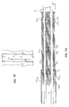
- Figure 1A is a sectional side view of the headbox of a paper/board machine in accordance with the invention, into which 0-water is passed along a duct of its own.
- Figure 1B shows the area X in Fig. 1A.
- Figure 1C is a sectional view taken along the line I-I in Fig. 1A. The figure is an illustration partly in section.
- Figure 1D is a sectional view taken along the line II-II in Fig. 1A. The figure is an illustration partly in section.
- Figure 1E is a sectional view taken along the line III-III in Fig. 1A.
- Figure 2A shows the construction of the mixing chamber of a turbulence tube in the turbulence generator on an enlarged scale.
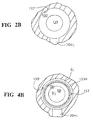
- Figure 2B is an enlarged sectional view taken along the line IV-IV in Fig. 2A.
- Figure 3 shows a second embodiment related to the mixing chamber of a turbulence tube.
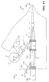
- Figure 4A shows a third preferred embodiment of the invention related to the mixing chamber of a turbulence tube in the turbulence generator.
- Figure 4B is an enlarged sectional view taken along the line V-V in Fig. 4A.
- Figure 5A shows an embodiment of the invention in which the diluting flow is passed into the system of distributor pipes.
- the figure is a schematic illustration of the headbox of a paper/board machine, into which headbox 0-water is passed along a duct of its own so as to regulate the mixing ratio at a certain position of width of the headbox and in which headbox an intermediate chamber comprises overflows so as to keep the flow quantity invariable as the mixing ratio is regulated.
- Figure 5B is a sectional view taken along the line VI-VI in Fig. 5A.
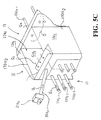
- Figure 5C is an axonometric illustration in part of the block construction in the direction of width of a paper/board machine as shown in Figs. 5A and 5B.
- Figure 6A is an illustration of principle and a sectional view of the headbox of a paper machine, which headbox comprises separate zones or blocks carried into effect by means of pipe connections and formed at different positions of width across the headbox of the paper/board machine.
- Figure 6B is a sectional view taken along the line VII-VII in Fig. 6A.
- Figure 6C is a sectional view taken along the line VIII-VIII in Fig. 6A.
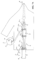
- Figure 7A shows an embodiment of the invention in which the flow quantity Q4 is regulated by means of valves fitted in the turbulence tubes in the upper row in the turbulence generator.
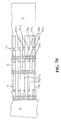
- Figure 7B is a sectional view taken along the line IX-IX in Fig. 7A.
- FIG. 1A shows the headbox of a paper/board machine in accordance with the invention, which headbox comprises, proceeding in the flow direction S of the pulp suspension M, an inlet header 10, a distributor manifold 11, in which there are distributor pipes 11a 1.1 ,11a 1.2 ...,11a 2.1, 11a 2.2 ... placed one above the other and side by side, an intermediate chamber 12, a turbulence generator 13, which comprises a number of turbulence tubes 13a 1.1 ,13a 2.1 ...,13a 1.2 ,13a 2.2 ...placed side by side and one above the other, and a discharge duct 14, into which the turbulence tubes 13a 1.1 ,13a 2.1 ...,13a 1.2 ,13a 2.2 ...
- the discharge duct 14 is defined by a stationary lower-lip wall 15 and by an upper-lip wall 16 pivoting around an articulated joint N.
- the headbox in accordance with the present invention of ours comprises an attenuation chamber 17, which is opened into the intermediate chamber.
- the attenuation chamber 17 extends across the entire width of the machine, and the intermediate chamber 12 communicates through a duct 18 with the interior space D of the attenuation chamber 17.
- the pressure in the space D When the pressure in the space D is regulated, the pressure level of the pulp M present in the intermediate chamber 12 is regulated, being maintained at the invariable level determined by the attenuation chamber 17. As is shown in Fig. 1A, an overflow Q2 is provided through the duct 18 into the attenuation chamber 17. Over the overflow threshold T, the flow Q2 enters into the trough G and further out of the trough G through the end ducts E. The pressure is passed into the space D through the flange joint M.
- the equalizing chamber 17 comprises an inner pressure space D, to which a flow Q is provided for the pulp M out of the intermediate chamber 12. Pressure is introduced into the space D in the equalizing chamber 17, and the discharge of the pressure out of the space D is regulated by means of a separate valve.
- the level of the pulp M passed into the equalizing chamber (flow Q2) in the space D is regulated, and so also the pressure that acts further upon the pulp M in the intermediate chamber 12.
- the flow Q2 into the equalizing chamber 17 passing further out through the trough G and back to the pulp circulation.
- the excess amount of the pulp M is removed from the intermediate chamber 12 that must be displaced when the diluting flow Q1 is introduced into the mixing point in order that the combined flow Q1 + Q3 remains at its invariable value.
- Fig. 1D is a sectional view taken along the line III-III in Fig. 1A.
- the equalizing chamber 17 extends across the entire machine width and, thus, from all positions of width of the equalizing chamber, there is a duct connection 18 into the intermediate chamber 12 extending across the machine width.
- the turbulence generator 13 is placed expressly after the intermediate chamber 12.
- a diluting flow Q 1.1 ,Q 1.2 ...Q 1.n is passed in a headbox of the sort mentioned above into the turbulence generator 13.
- each diluting flow Q 1.1 ,Q 1.2 ...Q 1.n is passed into different positions of width in the turbulence generator 13, preferably into the turbulence tubes 13a 3.1 ,13a 3.2 ...13a 3.n in the middle level, in which case, by means of the additional flow, i.e.
- the grammage of the paper is regulated at the position of width concerned as said additional flow is mixed, at each particular position of width, with the pulp M, with its pulp flow Q 3.1 ,Q 3.2 ...Q 3.n , which has been passed out of the intermediate chamber 12 into the turbulence tube 13a 3.1 ,13a 3.2 ...13a 3.n in the turbulence generator 13.
- the turbulence generator 13 shown in Fig. 1A comprises a number of turbulence tubes places side by side in the direction of width and in the vertical direction.
- the turbulence tubes 13a 3.1 ,13a 3.2 ...13a 3.n of the middle level are connected with an additional-flow duct 20a1 ,20a2...20a n , favourably a 0-water duct and favourably a pipe.
- valve 21a1,21a2...21a n by whose means the throttle of the additional flow Q 1.1 ,Q 1.2 ...Q 1.n is regulated and, thus, by whose means the flow velocity is regulated and the flow quantity is regulated that is passed out of the diluting-water inlet header 19 into the turbulence generator 13 into each particular compartment constituted by the tube 13a 3.1 ,13a 3.2 ...13a 3.n .
- the additional flow Q 1.1 ,Q 1.2 ...Q 1.n enters into the turbulence tube 13a 3.1 ,13a 3.2 ...
- Fig. 1B is a separate illustration of the area X in Fig. 1A.
- a pulp flow Q3 of normal concentration enters from the intermediate chamber 12 of the headbox.
- each additional flow Q1 is mixed efficiently with the pulp flow Q3.
- the additional flow Q 1.1 ,Q 1.2 ...Q 1.n is passed into the mixing chamber 130 in the turbulence tubes of the turbulence generator 13.
- uniform mixing of the flows Q1 and Q3 is permitted, and the uniform pressure maintained in the intermediate chamber 12 is passed to the mixing point.
- the middle layer in the turbulence generator is the layer that is used as the regulation layer, in which the additional flow, favourably a water flow, and the flow of the pulp (M) of average concentration coming out of the intermediate chamber 12 are combined.
- the flow of regulated concentration is passed through the turbulence generator 13, and said flow Q 4.1 , Q 4.2 ...Q 4.n joins, in the vertical direction, the other, non-regulated flows of the pulp (M) coming out of the other tubes in the turbulence generator, while, at each position of width of the web, the middle layer operates as the layer that regulates the grammage of the web.
- the headbox in accordance with the invention is regulated so that, during operation, the grammage is regulated expressly by means of regulation of the additional flow Q 1.1 ,Q 1.2 ...Q 1.n .
- the profile bar is not displaced and, thus, the systems of control and monitoring of the profile bar K are not maintained then. If there is a profile bar K, it is used just at the beginning of the run for advance regulation of the fibre orientation.
- the profile bar is never used for regulation of the grammage.
- the profile bar K comprises adjusting spindles with infrequent spacing and manual operation.
- the additional flow Q1 is favourably a flow that contains water alone or a so-called 0-water flow.
- the additional flow Q1 may also be a pulp flow whose concentration differs, on the whole, from the average concentration of the pulp suspension in the headbox and, thus, from the concentration of the flow Q3.
- Fig. 1C is a sectional view taken along the line I-I in Fig. 1A.
- Each additional-flow duct 20a1,20a2... preferably a pipe, comprises a valve 21a1,21a2..., in which case it is possible, in the direction of width of the paper machine, to adjust the desired mixing ratio for the flows Q 4.1 ,Q 4.2 ...Q 4.n at each position of width, which flow, as it comes out of the turbulence generator 13 out of its turbulence tube 13a1,13a2..., acts further as a regulation flow at the desired location of width of the pulp suspension jet.
- Fig. 1D is a sectional view taken along the line II-II in Fig. 1A.
- the diluting liquid preferably diluting water
- the duct 20a1,20a2... and by means of the valve 21a1,21a2... placed in each duct, preferably a pipe, said diluting flow is regulated by throttling said flow in accordance with the regulation of the valve.
- Fig. 1E is a sectional view of the attenuation chamber 17 shown in Fig. 1A. As is shown in the figure, the attenuation chamber 17 extends across the entire machine width.
- Fig. 2A is an enlarged illustration of the solution shown in Fig. 1B.
- a flow Q 3.1 passes into the mixing chamber 130 in the turbulence tube 13a 3.1 of the turbulence generator 13.
- a flow duct 20a1 is provided for the diluting flow.
- the flow duct joins the mixing chamber halfway in relation to the length of the mixing chamber.
- the sectional flow area of the mixing chamber 130 in the direction of the flow S (arrow S) is A1, and this area is substantially larger than the sectional flow area A2 of the duct portion 131 following after the mixing chamber in the turbulence tube in the turbulence generator.
- Figure 2B is a sectional view taken along the line IV-IV in Fig. 2A.
- Fig. 3 shows a second preferred embodiment of the construction related to the mixing chamber.
- the flange piece 1320 comprises a flow duct 132.
- the flow duct 132 comprises a straight duct portion 132a1 of circular section and therein a sectional flow area A3 and a conically widening duct portion 132a3, which is connected with the walls 130' of the mixing chamber 130.
- the flow duct 132 is placed between the intermediate chamber 12 and the mixing chamber 130.
- the sectional flow area A3 is substantially smaller than the sectional flow area A1 of the mixing chamber 130.
- the flange piece 1320 is connected, by means of a press fitting or a threaded joint, with the recess f1 that has been made into the face of the frame 13R of the turbulence generator 13 defined by the intermediate chamber 12. Also in this embodiment, the mixing chamber 130 is followed by a duct portion 131 in the turbulence tube, whose sectional flow area is substantially smaller than the sectional flow area of the mixing chamber 130.
- Fig. 4A shows an embodiment related to the mixing chamber, wherein a pipe or duct 133 extends from the intermediate chamber 12 into the mixing chamber 130.
- the pipe 133 extends into the mixing chamber 130 so that the pipe is opened in the end of the mixing chamber 130 and is placed centrally on the central axis X1 of the mixing chamber 130.
- the flow Q3 from the intermediate chamber 12 enters through the pipe 133 into the mixing chamber 130.
- the pipe 133 On its outer face 133', the pipe 133 comprises a throttle flange 133d, preferably an annular flange, which projects from said outer face and by whose means the diluting flow Q1 is throttled.
- the annular flange 133d is placed on the circular circumference of the pipe 133.
- the diluting flow Q 1.1 is passed into the space between the pipe 133 face 133' and the mixing-chamber 130 face 130', in the way shown in Fig. 4, along two diluting ducts 20a1', 20a1.
- the pipe 133 comprises a flange 133c, preferably an annular flange, at its end, by means of which flange the pipe is connected with the recess f2 in the frame 13R of the turbulence generator.
- the joint is accomplished either by means of a press fitting or by means of a threaded joint. It can also be accomplished by gluing.
- the front face of the flange 133c is placed facing the intermediate chamber 12.
- Fig. 4B is a sectional view taken along the line V-V in Fig. 4A.
- the flow Q1 out of the additional-flow duct 20a1 passes annularly to the end of the pipe 133 bypassing the flange 133d of the pipe.
- the flows Q3 and Q1 are combined in the mixing chamber 130 at the end of the pipe 133.
- FIG. 5A shows the headbox of a paper/board machine in accordance with the invention, which headbox comprises, proceeding in the flow direction S of the pulp suspension M, an inlet header 10, a distribution manifold 11, an intermediate chamber, i.e., in the present case, a mixing chamber 12, a turbulence generator 13, which comprises a number of turbulence tubes 13a 1.1 ,13a 2.1 ...,13a 1.2 ,13a 2.2 ... placed side by side and one above the other, and a discharge duct 14, into which the turbulence tubes 13a 1.1 ,13a 2.1 ...,13a 1.2 ,13a 2.2 ... of the turbulence generator 13 are opened.
- the discharge duct 14 is defined by a stationary lower-lip wall 15 and by an upper-lip wall 16 pivoting around an articulated joint.
- the intermediate chamber 12 has been divided, in the direction of width of the headbox of the paper machine, into a number of zones or blocks 12a1,12a2... 12a n placed side by side.
- Each block 12a1,12a2... is connected with an additional-flow duct 20a1,20a2...20a n , preferably a 0-water duct and preferably a pipe.
- Each flow duct 20a1,20a2... comprises a valve 21a1,21a2...21a n , by whose means the throttle of the additional flow Q1 and, thus, its velocity and the flow quantity that is passed into the intermediate chamber 12, into its zone 12a1,12a2,12a3...12a n concerned at each particular time are regulated.
- Each zone 12a1,12a2... is connected with a distribution pipe 11a1,11a2... of the distribution manifold 11. From the inlet header 10, a pulp flow of average concentration is passed through the distribution pipe 11a1,11a2... into the intermediate chamber 12 of the headbox of the paper machine, into the various zones 12a1,12a2... in said chamber 12.
- Each additional flow Q1 is introduced through the duct 20a1, 20a2... at a high velocity, whereby it is mixed in the zones 12a1,12a2... in the intermediate chamber 12 efficiently with the pulp flow Q3.
- the mixed flow Q4 is passed into the turbulence generator 13 into the turbulence tubes 13a1,13a2,13a3...,13a n in its upper row.
- each mixing zone 12a1,12a2... has been arranged as a compartment in the direction of width of the headbox so that each zone 12a1,12a2... is separate and does not communicate with the adjacent zone.
- an overflow 22a1 ,22a2...22a n has been arranged into the attenuation chamber 17.
- the overflows 22a1 ,22a2... have a common air space 23.
- Each overflow has been formed preferably from a space fitted above the zones 12a1, 12a2... in the intermediate chamber 12, which space comprises an air space common of the overflows 22a1 ,22a2... and separate overflow thresholds 180a1,180a2... for each overflow.
- Each overflow space is defined in relation to the adjacent spaces by means of partition walls 170a1,170a2...
- the overflow threshold 180a1, 180a2... by regulating the height of the overflow threshold 180a1, 180a2..., it is possible to regulate the pressure that prevails in the zone 12a1, 12a2... in the intermediate chamber 12, and in this way, by regulating the position of the overflow threshold, it is possible to regulate the flow quantity of the flow Q4 departing from the compartments 12a1, 12a2...
- the overflows are opened into a common exhaust duct E1.
- the exhaust flow is produced as an overflow Q2.
- the mixed flow Q4 passed into and out of the turbulence generator 13 has a quantity equal to the flow Q3 coming out of the distribution tube 11a1,11a2...
- the mixing ratio is regulated by bringing the additional flow Q1 into the flow Q3 along the duct 20a1,20a2...
- the flow quantity Q4 passing into the turbulence tube 13a1,13a2 of the turbulence generator 13 is kept invariable.
- the quantity of the overflow Q2 is equal to the quantity of the additional flow Q1 that was introduced.
- the additional flow Q1 is preferably a flow consisting of water alone, i.e. a so-called 0-water flow.
- the additional flow Q1 may also be a pulp flow whose concentration differs, on the whole, from the average concentration of the pulp suspension in the headbox and, thus, from the concentration of the flow Q3.
- Fig. 5B is a sectional view taken along the line VI-VI in Fig. 5A.
- each overflow zone or block 12a1,12a2...12a n is defined by partition walls 170a1, 170a2...
- the overflows of the zones 12a1, 12a2... are opened into the common outlet E placed at the other side of the overflow threshold 180.
- the zones or blocks 12a1,12a2...12a n may be formed so that, at each location of width, the walls 170a1,170a2 extend vertically from the lower part of the intermediate chamber in the headbox to its upper part and further into the overflow space, where they divide each overflow space into blocks at the zone of said location of width.
- the zones 12a1, 12a2... may also have been formed so that they comprise a bottom part D, in which case the blocks or zones 12a1,12a2... have been formed into the intermediate chamber 12 of the headbox of the paper machine at each location of width in same and so that the blocks are placed in the upper part of the intermediate chamber 12 and are defined by the walls 170a1,170a2 and by the bottom part D.
- Fig. 5C is an axonometric illustration in part of the arrangement in blocks of the headbox of a paper machine in the direction of width as illustrated above in order to permit regulation of the consistency and of the fibre orientation of the pulp suspension at the desired location of width independently from one another.
- Fig. 6A is an illustration of principle of the headbox of a paper machine, which headbox is in the other respects similar to the embodiment shown in Figs. 5A to 5C, except that the arrangement in compartments has been carried out by means of pipe connections.
- a valve 24a1 ,24a2 has been fitted in each overflow pipe 220a1,220a2...
- each additional flow Q 1.1 ,Q 1.2 ...Q 1.n is passed from the inlet header 25, being regulated by the valves 21a1,21a2... placed in the additional-flow pipes 20a1,20a2..., directly into the distribution tube 11a1,11a2... in the distribution manifold 11.
- the distribution tube 11a1,11a2... passes further into a separate pipe 26a1,26a2... placed in the intermediate chamber 12, which pipe 26a1,26a2... is connected with an overflow pipe 220a1 ,220a2...
- the overflow pipe 220a1 ,220a2... is opened into an attenuation chamber 17, which comprises a collecting chamber 28 common of the overflows 220a1 ,220a2..., a common air space 23, a common overflow threshold 29, and a common outlet E.
- Fig. 6B is a sectional view taken along the line VII-VII in Fig. 6A.
- the pipe 26a1, 26a2... placed in the intermediate chamber 12 prevents mixing of the combined flow Q3 + Q1 with the rest of the pulp flow in the intermediate chamber 12.
- Fig. 6C is a sectional view taken along the line VIII-VIII in Fig. 6A.
- Fig. 7A shows an embodiment of the invention in which the flow quantity Q4 is regulated by means of valves 31a1,31a2...31a n , which are placed in turbulence tubes 13a1, 13a2... adjacent to one another in the direction of width in the upper row in the turbulence generator 13.
- Fig. 7B is a sectional view taken along the line IX-IX in Fig. 7A.
- the invention concerns a method and a device in the regulation of the headbox.
- the headbox comprises a pulp (M) inlet header (10), after the pulp inlet header (10), seen in the pulp (M) flow direction, a distributor manifold (11), whose pipes (11a 1.1 ,11a 1.2 ...) are opened into an intermediate chamber (12).
- the headbox comprises an attenuation chamber (17) placed in connection with the intermediate chamber (12) and, after the intermediate chamber (12), a turbulence generator (13), whose tubes (13a 1.1 ,13a 1.2 ..., 13a 2.1 , 13a 2.2 ...)are opened, at their outlet end, into the discharge duct (14) and, at their inlet end, into the intermediate chamber (12).
- a pulp suspension (M) flow (Q 4.1 ,Q 4.2 ...Q 4.n ) is introduced, the concentration of said flow being adjustable by means of combining of two component flows (Q1, Q2).
- the concentration of said flow being adjustable by means of combining of two component flows (Q1, Q2).
- two component flows are combined by into the pulp suspension flow (Q 3.1 , Q 3.2 ...Q 3.n ) introducing an additional flow (Q 1.1 , Q 1.2 ...Q 1.n ).
- the mixing ratio of the combined flow is regulated by adjusting said additional flow (Q 1.1 ,Q 1.2 ...Q 1.n ).
- the additional flow (Q 1.1 ,Q 1.2 ,Q 1.3 ...Q 1.n ) is passed into the pulp (M) flow taken out of the inlet header.
Landscapes
- Paper (AREA)
- Blow-Moulding Or Thermoforming Of Plastics Or The Like (AREA)
- Earth Drilling (AREA)
Priority Applications (1)
| Application Number | Priority Date | Filing Date | Title |
|---|---|---|---|
| EP00127079A EP1099793B1 (fr) | 1993-07-01 | 1994-06-30 | Procédé et dispositif pour la régulation d' une caisse de tête |
Applications Claiming Priority (4)
| Application Number | Priority Date | Filing Date | Title |
|---|---|---|---|
| FI933027 | 1993-07-01 | ||
| FI933027A FI92228C (fi) | 1993-07-01 | 1993-07-01 | Menetelmä ja laite perälaatikon säädössä |
| FI942780A FI942780A7 (fi) | 1994-06-13 | 1994-06-13 | Menetelmä ja laite perälaatikon säädössä |
| FI942780 | 1994-06-13 |
Related Child Applications (1)
| Application Number | Title | Priority Date | Filing Date |
|---|---|---|---|
| EP00127079A Division EP1099793B1 (fr) | 1993-07-01 | 1994-06-30 | Procédé et dispositif pour la régulation d' une caisse de tête |
Publications (2)
| Publication Number | Publication Date |
|---|---|
| EP0635599A1 true EP0635599A1 (fr) | 1995-01-25 |
| EP0635599B1 EP0635599B1 (fr) | 2002-01-23 |
Family
ID=26159539
Family Applications (2)
| Application Number | Title | Priority Date | Filing Date |
|---|---|---|---|
| EP94110236A Expired - Lifetime EP0635599B1 (fr) | 1993-07-01 | 1994-06-30 | Procédé et dispositif pour la régulation d'une caisse de tête |
| EP00127079A Expired - Lifetime EP1099793B1 (fr) | 1993-07-01 | 1994-06-30 | Procédé et dispositif pour la régulation d' une caisse de tête |
Family Applications After (1)
| Application Number | Title | Priority Date | Filing Date |
|---|---|---|---|
| EP00127079A Expired - Lifetime EP1099793B1 (fr) | 1993-07-01 | 1994-06-30 | Procédé et dispositif pour la régulation d' une caisse de tête |
Country Status (6)
| Country | Link |
|---|---|
| US (2) | US5545293A (fr) |
| EP (2) | EP0635599B1 (fr) |
| JP (1) | JP3576601B2 (fr) |
| AT (2) | ATE212393T1 (fr) |
| CA (1) | CA2127309C (fr) |
| DE (2) | DE69429693T2 (fr) |
Cited By (10)
| Publication number | Priority date | Publication date | Assignee | Title |
|---|---|---|---|---|
| WO1997033038A1 (fr) * | 1996-03-08 | 1997-09-12 | Valmet-Karlstad Ab | Configuration pour amenee de matiere a une bache de machine de fabrication du papier |
| WO1997048851A1 (fr) * | 1996-06-20 | 1997-12-24 | Valmet Corporation | Melangeur pour diluant et pate a papier alimentant le caisson de distribution d'une machine a papier ou carton |
| WO1998001619A1 (fr) * | 1996-07-04 | 1998-01-15 | Valmet Corporation | Equipement connecte a la caisse de tete d'une machine a papier/a carton |
| WO1998041685A1 (fr) * | 1997-03-14 | 1998-09-24 | Valmet Corporation | Systeme de regulation de machine a papier permettant de reguler la variation de la force du papier dans le sens de fabrication |
| US5853545A (en) * | 1996-03-08 | 1998-12-29 | Valmet-Karlstad Ab | Arrangement for feeding stock to a headbox in a papermaking machine |
| EP1033436A3 (fr) * | 1999-03-02 | 2001-03-21 | Voith Paper Patent GmbH | Procédé et dispositif pour le dosage d'un milieu fluide dans l'écoulement d'une suspension dans une caisse de tête |
| EP1195463A3 (fr) * | 2000-10-04 | 2003-04-09 | Sandusky Walmsley Ltd. | Caisse de tête pour machine à papier |
| EP1496150A1 (fr) * | 2003-07-09 | 2005-01-12 | Voith Paper Patent GmbH | Caisse de tête |
| WO2005024127A1 (fr) * | 2003-09-09 | 2005-03-17 | Metso Paper, Inc. | Appareil connecte a la caisse d'arrivee d'une machine a papier ou analogue |
| EP3187656A1 (fr) | 2015-12-28 | 2017-07-05 | Valmet Technologies Oy | Procédé de production de balles de pâte à papier et agencement pour contrôler le profil de poids des balles dans une machine à sécher la pâte à papier |
Families Citing this family (18)
| Publication number | Priority date | Publication date | Assignee | Title |
|---|---|---|---|---|
| DE69429693T2 (de) * | 1993-07-01 | 2002-08-08 | Metso Paper, Inc. | Verfahren und Vorrichtung zur Regelung eines Stoffauflaufkasten |
| DE4437180C2 (de) * | 1994-10-18 | 1997-03-20 | Voith Sulzer Papiermasch Gmbh | Verfahren zur Herstellung eines Stoffauflaufes und Zwischenteil eines Stoffaufllaufes einer Papier- oder Kartonmaschine |
| DE9416731U1 (de) * | 1994-10-18 | 1995-01-12 | Sulzer-Escher Wyss Gmbh, 88212 Ravensburg | Stoffauflauf für eine Papiermaschine |
| US5812404A (en) * | 1996-04-18 | 1998-09-22 | Valmet Corporation | Method for overall regulation of the headbox of a paper machine or equivalent |
| FI110879B (fi) * | 1996-10-23 | 2003-04-15 | Metso Paper Inc | Laitteisto laimennusnesteen virtauksen säädössä paperikoneen/kartonkikoneen perälaatikon yhteydessä |
| US6113741A (en) * | 1996-12-06 | 2000-09-05 | Eka Chemicals Ab | Process for the production of paper |
| DE19654390A1 (de) * | 1996-12-27 | 1998-07-02 | Basf Ag | Verfahren zur Herstellung von Papier |
| FI115645B (fi) * | 1997-01-14 | 2005-06-15 | Metso Paper Inc | Paperikoneen perälaatikko, jossa on reunasyöttöjärjestelyt |
| US5833808A (en) * | 1997-01-21 | 1998-11-10 | Beloit Technologies, Inc. | Method of controlling curl employing inline headbox edge flow control valve |
| DE19843729A1 (de) * | 1998-09-24 | 2000-03-30 | Voith Sulzer Papiertech Patent | Verfahren und Vorrichtung zur Verbesserung des Schrumpfungs-Querprofils |
| FI112961B (fi) | 1998-11-26 | 2004-02-13 | Metso Paper Inc | Menetelmä ja laite paperikoneen/kartonkikoneen retentioprofiilin mittaamiseksi ja retention hallitsemiseksi |
| FI116078B (fi) * | 1998-12-30 | 2005-09-15 | Metso Paper Inc | Menetelmä massan syöttämiseksi perälaatikkoon |
| FI117292B (fi) * | 2000-06-13 | 2006-08-31 | Metso Paper Inc | Paperikoneen tai vastaavan perälaatikko |
| ZA200508659B (en) * | 2003-05-09 | 2007-03-28 | Akzo Nobel Nv | A process for the production of paper |
| FI20105467L (fi) * | 2010-04-29 | 2011-10-30 | Metso Paper Inc | Menetelmä ja laitteisto reunasyötön järjestämiseksi kuiturainakoneen perälaatikon yhteyteen |
| JP6292078B2 (ja) * | 2014-08-08 | 2018-03-14 | 王子ホールディングス株式会社 | 繊維強化プラスチック成形体用基材抄造装置および繊維強化プラスチック成形体用基材抄造方法 |
| CN107083715A (zh) * | 2017-06-22 | 2017-08-22 | 北塘区军之印纸品加工厂 | 一种纸品生产用流浆箱装置 |
| AU2022299328A1 (en) | 2021-06-25 | 2024-02-01 | Kimberly-Clark Worldwide, Inc. | Process and system for reorienting fibers in a foam forming process |
Citations (5)
| Publication number | Priority date | Publication date | Assignee | Title |
|---|---|---|---|---|
| WO1986001844A1 (fr) * | 1984-09-19 | 1986-03-27 | Sulzer-Escher Wyss Gmbh | Systeme de caisse de tete pour machine a papier, et procede pour son utilisation |
| EP0462472A1 (fr) * | 1990-06-20 | 1991-12-27 | J.M. Voith GmbH | Caisse de tête de machines à papier |
| DE9115296U1 (de) * | 1991-12-10 | 1992-03-19 | J.M. Voith Gmbh, 7920 Heidenheim | Stoffauflauf |
| DE4239845A1 (en) * | 1992-11-05 | 1993-05-19 | Voith Gmbh J M | Paper-making inlet correction - uses correlated measurements from start and end of water extraction stage to calculate the settings |
| WO1993022495A1 (fr) * | 1992-04-25 | 1993-11-11 | Sulzer-Escher Wyss Gmbh | Agencement de caisse de tete pour machines a papier |
Family Cites Families (14)
| Publication number | Priority date | Publication date | Assignee | Title |
|---|---|---|---|---|
| DE1785344C3 (de) * | 1968-09-13 | 1974-11-07 | Basf Ag, 6700 Ludwigshafen | Vorrichtung zur Kräuselung von Garnen od.dgl |
| US3791918A (en) * | 1972-03-08 | 1974-02-12 | Valmet Oy | Headbox of a paper making machine having multiple, vertically inclined vanes |
| US4146425A (en) * | 1974-10-02 | 1979-03-27 | Sulzer Brothers Limited | Papermaking machine headbox having a feed channel and an adjacent overflow sump |
| US4137439A (en) * | 1977-06-24 | 1979-01-30 | Electro Switch Corp. | Selector switch relay |
| SE421328B (sv) * | 1978-04-25 | 1981-12-14 | Karlstad Mekaniska Ab | Forfarande och anordning for bildande av en flerskiktsmeldstrale |
| US4637439A (en) * | 1981-02-09 | 1987-01-20 | Cadbury Schweppes, Plc | Mini-regulator valve assembly |
| FI83549C (fi) * | 1986-09-19 | 1991-07-25 | Valmet Oy | Foerfarande och anordning vid inloppslaodan och dess tillstroemningssystem i en pappersmaskin. |
| DE3741603A1 (de) * | 1987-12-09 | 1989-06-22 | Voith Gmbh J M | Stoffauflauf fuer eine papiermaschine od.dgl. |
| CA1337379C (fr) * | 1988-07-11 | 1995-10-24 | John Mckernan | Manchon pour pene dormant |
| FI79363C (fi) * | 1988-09-26 | 1989-12-11 | Valmet Paper Machinery Inc | Foerfarande och anordning i inloppslaodan av en pappersmaskin foer att behaerska foerdelningen i pappersbanans fiberorientering. |
| US5133836A (en) * | 1991-09-20 | 1992-07-28 | Kimberly-Clark Corporation | Papermaking headbox having extended divider sheet |
| DE4211291C3 (de) * | 1992-04-03 | 2001-06-07 | Voith Gmbh J M | Mischeinrichtung und Verfahren zum Mischen von zwei Flüssigkeiten bei konstantem Gemischvolumenstrom zur Versorgung des Stoffauflaufs einer Papiermaschine |
| DE69429693T2 (de) * | 1993-07-01 | 2002-08-08 | Metso Paper, Inc. | Verfahren und Vorrichtung zur Regelung eines Stoffauflaufkasten |
| DE4323263C2 (de) * | 1993-07-12 | 2001-11-29 | Voith Paper Patent Gmbh | Verfahren zur sektionalen Beeinflussung der Stoffdichte und der Faserorientierung in einem Stoffauflauf einer Papiermaschine und Stoffauflauf zur Durchführung des Verfahrens |
-
1994
- 1994-06-30 DE DE69429693T patent/DE69429693T2/de not_active Expired - Fee Related
- 1994-06-30 EP EP94110236A patent/EP0635599B1/fr not_active Expired - Lifetime
- 1994-06-30 AT AT94110236T patent/ATE212393T1/de not_active IP Right Cessation
- 1994-06-30 AT AT00127079T patent/ATE335100T1/de active
- 1994-06-30 DE DE69434813T patent/DE69434813T2/de not_active Expired - Lifetime
- 1994-06-30 EP EP00127079A patent/EP1099793B1/fr not_active Expired - Lifetime
- 1994-07-01 JP JP17341194A patent/JP3576601B2/ja not_active Expired - Fee Related
- 1994-07-01 US US08/269,566 patent/US5545293A/en not_active Expired - Lifetime
- 1994-07-04 CA CA002127309A patent/CA2127309C/fr not_active Expired - Fee Related
-
1996
- 1996-05-01 US US08/640,511 patent/US5688372A/en not_active Expired - Fee Related
Patent Citations (5)
| Publication number | Priority date | Publication date | Assignee | Title |
|---|---|---|---|---|
| WO1986001844A1 (fr) * | 1984-09-19 | 1986-03-27 | Sulzer-Escher Wyss Gmbh | Systeme de caisse de tete pour machine a papier, et procede pour son utilisation |
| EP0462472A1 (fr) * | 1990-06-20 | 1991-12-27 | J.M. Voith GmbH | Caisse de tête de machines à papier |
| DE9115296U1 (de) * | 1991-12-10 | 1992-03-19 | J.M. Voith Gmbh, 7920 Heidenheim | Stoffauflauf |
| WO1993022495A1 (fr) * | 1992-04-25 | 1993-11-11 | Sulzer-Escher Wyss Gmbh | Agencement de caisse de tete pour machines a papier |
| DE4239845A1 (en) * | 1992-11-05 | 1993-05-19 | Voith Gmbh J M | Paper-making inlet correction - uses correlated measurements from start and end of water extraction stage to calculate the settings |
Cited By (16)
| Publication number | Priority date | Publication date | Assignee | Title |
|---|---|---|---|---|
| US5853545A (en) * | 1996-03-08 | 1998-12-29 | Valmet-Karlstad Ab | Arrangement for feeding stock to a headbox in a papermaking machine |
| US6030500A (en) * | 1996-03-08 | 2000-02-29 | Valmet-Karlstad Ab | Arrangement for feeding stock to a headbox in a papermaking machine |
| WO1997033038A1 (fr) * | 1996-03-08 | 1997-09-12 | Valmet-Karlstad Ab | Configuration pour amenee de matiere a une bache de machine de fabrication du papier |
| CN1075851C (zh) * | 1996-06-20 | 2001-12-05 | 韦尔梅特公司 | 使造纸/纸板机中的稀释流与流出入口集管的纸浆流相混合的装置 |
| WO1997048851A1 (fr) * | 1996-06-20 | 1997-12-24 | Valmet Corporation | Melangeur pour diluant et pate a papier alimentant le caisson de distribution d'une machine a papier ou carton |
| WO1998001619A1 (fr) * | 1996-07-04 | 1998-01-15 | Valmet Corporation | Equipement connecte a la caisse de tete d'une machine a papier/a carton |
| WO1998041685A1 (fr) * | 1997-03-14 | 1998-09-24 | Valmet Corporation | Systeme de regulation de machine a papier permettant de reguler la variation de la force du papier dans le sens de fabrication |
| US6464837B1 (en) | 1999-03-02 | 2002-10-15 | Voith Sulzer Papiertechnik Patent Gmbh | Headbox and process for the metered addition of a fluid medium into a suspension stream of a headbox |
| EP1033436A3 (fr) * | 1999-03-02 | 2001-03-21 | Voith Paper Patent GmbH | Procédé et dispositif pour le dosage d'un milieu fluide dans l'écoulement d'une suspension dans une caisse de tête |
| US6890408B2 (en) | 1999-03-02 | 2005-05-10 | Voith Sulzer Papiertechnik Patent Gmbh | Headbox for the metered addition of a fluid medium into a suspension stream |
| EP1195463A3 (fr) * | 2000-10-04 | 2003-04-09 | Sandusky Walmsley Ltd. | Caisse de tête pour machine à papier |
| US7001488B2 (en) | 2000-10-04 | 2006-02-21 | Sandusky Technologies Limited | Method of and apparatus for distribution of paper stock in paper or board making machinery |
| EP1496150A1 (fr) * | 2003-07-09 | 2005-01-12 | Voith Paper Patent GmbH | Caisse de tête |
| WO2005024127A1 (fr) * | 2003-09-09 | 2005-03-17 | Metso Paper, Inc. | Appareil connecte a la caisse d'arrivee d'une machine a papier ou analogue |
| US7485206B2 (en) | 2003-09-09 | 2009-02-03 | Metso Paper, Inc. | Apparatus in connection with a headbox of a paper machine or equivalent |
| EP3187656A1 (fr) | 2015-12-28 | 2017-07-05 | Valmet Technologies Oy | Procédé de production de balles de pâte à papier et agencement pour contrôler le profil de poids des balles dans une machine à sécher la pâte à papier |
Also Published As
| Publication number | Publication date |
|---|---|
| ATE212393T1 (de) | 2002-02-15 |
| CA2127309A1 (fr) | 1995-01-02 |
| EP1099793A2 (fr) | 2001-05-16 |
| EP1099793B1 (fr) | 2006-08-02 |
| DE69429693D1 (de) | 2002-03-14 |
| JPH07166489A (ja) | 1995-06-27 |
| DE69434813T2 (de) | 2007-01-04 |
| DE69434813D1 (de) | 2006-09-14 |
| DE69429693T2 (de) | 2002-08-08 |
| ATE335100T1 (de) | 2006-08-15 |
| CA2127309C (fr) | 2000-05-02 |
| US5545293A (en) | 1996-08-13 |
| EP1099793A3 (fr) | 2003-05-07 |
| EP0635599B1 (fr) | 2002-01-23 |
| US5688372A (en) | 1997-11-18 |
| JP3576601B2 (ja) | 2004-10-13 |
Similar Documents
| Publication | Publication Date | Title |
|---|---|---|
| EP0635599A1 (fr) | Procédé et dispositif pour la régulation d'une caisse de tête | |
| EP0635600A1 (fr) | Procédé et dispositif pour la régulation d'un caisse de tête | |
| US4897158A (en) | Headbox apparatus for a papermaking machine | |
| EP0634523B1 (fr) | Caisse de tête à plusieurs couches | |
| US5401363A (en) | Method of homogenizing the constitution of a web of paper | |
| US4687548A (en) | Method and apparatus for controlling distortion of fibre orientation in a paper web | |
| US5549792A (en) | Headbox for a paper machine | |
| FI90260B (fi) | Perälaatikko paperikonetta tai vastaavaa varten | |
| FI115645B (fi) | Paperikoneen perälaatikko, jossa on reunasyöttöjärjestelyt | |
| CA2177927C (fr) | Caisse de tete pour machine a papier | |
| US5674363A (en) | Method and device in the regulation of a headbox | |
| US5958189A (en) | Wet part of a paper making machine | |
| WO1998023812A1 (fr) | Caisse de tete multi-couche pour machine a papier/machine a carton | |
| US5573642A (en) | Method and device for evening out the basic weight cross section by sectioning the screen circuit | |
| US5510005A (en) | Venturi headbox for a papermaking machine | |
| US6821390B2 (en) | Process and device to control quality parameters in paper, tissue and pulp dewatering plants | |
| FI92730B (fi) | Menetelmä ja laite perälaatikon säädössä | |
| FI98385C (fi) | Paperi- tai kartonkikoneen perälaatikko | |
| FI92228B (fi) | Menetelmä ja laite perälaatikon säädössä | |
| FI97738B (fi) | Paperi- tai kartonkikoneen perälaatikko | |
| FI93980C (fi) | Menetelmä ja laite perälaatikon säädössä |
Legal Events
| Date | Code | Title | Description |
|---|---|---|---|
| PUAI | Public reference made under article 153(3) epc to a published international application that has entered the european phase |
Free format text: ORIGINAL CODE: 0009012 |
|
| AK | Designated contracting states |
Kind code of ref document: A1 Designated state(s): AT CH DE FR GB IT LI SE |
|
| 17P | Request for examination filed |
Effective date: 19950330 |
|
| 17Q | First examination report despatched |
Effective date: 19980909 |
|
| GRAG | Despatch of communication of intention to grant |
Free format text: ORIGINAL CODE: EPIDOS AGRA |
|
| GRAG | Despatch of communication of intention to grant |
Free format text: ORIGINAL CODE: EPIDOS AGRA |
|
| GRAH | Despatch of communication of intention to grant a patent |
Free format text: ORIGINAL CODE: EPIDOS IGRA |
|
| RAP1 | Party data changed (applicant data changed or rights of an application transferred) |
Owner name: METSO PAPER, INC. |
|
| GRAH | Despatch of communication of intention to grant a patent |
Free format text: ORIGINAL CODE: EPIDOS IGRA |
|
| GRAA | (expected) grant |
Free format text: ORIGINAL CODE: 0009210 |
|
| REG | Reference to a national code |
Ref country code: GB Ref legal event code: IF02 |
|
| AK | Designated contracting states |
Kind code of ref document: B1 Designated state(s): AT CH DE FR GB IT LI SE |
|
| PG25 | Lapsed in a contracting state [announced via postgrant information from national office to epo] |
Ref country code: LI Free format text: LAPSE BECAUSE OF FAILURE TO SUBMIT A TRANSLATION OF THE DESCRIPTION OR TO PAY THE FEE WITHIN THE PRESCRIBED TIME-LIMIT Effective date: 20020123 Ref country code: IT Free format text: LAPSE BECAUSE OF FAILURE TO SUBMIT A TRANSLATION OF THE DESCRIPTION OR TO PAY THE FEE WITHIN THE PRESCRIBED TIME-LIMIT;WARNING: LAPSES OF ITALIAN PATENTS WITH EFFECTIVE DATE BEFORE 2007 MAY HAVE OCCURRED AT ANY TIME BEFORE 2007. THE CORRECT EFFECTIVE DATE MAY BE DIFFERENT FROM THE ONE RECORDED. Effective date: 20020123 Ref country code: FR Free format text: LAPSE BECAUSE OF FAILURE TO SUBMIT A TRANSLATION OF THE DESCRIPTION OR TO PAY THE FEE WITHIN THE PRESCRIBED TIME-LIMIT Effective date: 20020123 Ref country code: CH Free format text: LAPSE BECAUSE OF FAILURE TO SUBMIT A TRANSLATION OF THE DESCRIPTION OR TO PAY THE FEE WITHIN THE PRESCRIBED TIME-LIMIT Effective date: 20020123 |
|
| REF | Corresponds to: |
Ref document number: 212393 Country of ref document: AT Date of ref document: 20020215 Kind code of ref document: T |
|
| REG | Reference to a national code |
Ref country code: CH Ref legal event code: EP |
|
| REF | Corresponds to: |
Ref document number: 69429693 Country of ref document: DE Date of ref document: 20020314 |
|
| PG25 | Lapsed in a contracting state [announced via postgrant information from national office to epo] |
Ref country code: GB Free format text: LAPSE BECAUSE OF NON-PAYMENT OF DUE FEES Effective date: 20020630 |
|
| REG | Reference to a national code |
Ref country code: CH Ref legal event code: PL |
|
| EN | Fr: translation not filed | ||
| PLBE | No opposition filed within time limit |
Free format text: ORIGINAL CODE: 0009261 |
|
| STAA | Information on the status of an ep patent application or granted ep patent |
Free format text: STATUS: NO OPPOSITION FILED WITHIN TIME LIMIT |
|
| 26N | No opposition filed | ||
| GBPC | Gb: european patent ceased through non-payment of renewal fee |
Effective date: 20020630 |
|
| PGFP | Annual fee paid to national office [announced via postgrant information from national office to epo] |
Ref country code: AT Payment date: 20080616 Year of fee payment: 15 |
|
| PGFP | Annual fee paid to national office [announced via postgrant information from national office to epo] |
Ref country code: SE Payment date: 20080612 Year of fee payment: 15 Ref country code: DE Payment date: 20080620 Year of fee payment: 15 |
|
| EUG | Se: european patent has lapsed | ||
| PG25 | Lapsed in a contracting state [announced via postgrant information from national office to epo] |
Ref country code: DE Free format text: LAPSE BECAUSE OF NON-PAYMENT OF DUE FEES Effective date: 20100101 Ref country code: AT Free format text: LAPSE BECAUSE OF NON-PAYMENT OF DUE FEES Effective date: 20090630 |
|
| PG25 | Lapsed in a contracting state [announced via postgrant information from national office to epo] |
Ref country code: SE Free format text: LAPSE BECAUSE OF NON-PAYMENT OF DUE FEES Effective date: 20090701 |