EP0635625A1 - Méthode et appareil d'incinération de la suie d'un filtre pour particules solides d'un moteur diesel - Google Patents
Méthode et appareil d'incinération de la suie d'un filtre pour particules solides d'un moteur diesel Download PDFInfo
- Publication number
- EP0635625A1 EP0635625A1 EP94105211A EP94105211A EP0635625A1 EP 0635625 A1 EP0635625 A1 EP 0635625A1 EP 94105211 A EP94105211 A EP 94105211A EP 94105211 A EP94105211 A EP 94105211A EP 0635625 A1 EP0635625 A1 EP 0635625A1
- Authority
- EP
- European Patent Office
- Prior art keywords
- soot
- filter
- process according
- ceramic
- magnetic
- Prior art date
- Legal status (The legal status is an assumption and is not a legal conclusion. Google has not performed a legal analysis and makes no representation as to the accuracy of the status listed.)
- Withdrawn
Links
Images



Classifications
-
- F—MECHANICAL ENGINEERING; LIGHTING; HEATING; WEAPONS; BLASTING
- F01—MACHINES OR ENGINES IN GENERAL; ENGINE PLANTS IN GENERAL; STEAM ENGINES
- F01N—GAS-FLOW SILENCERS OR EXHAUST APPARATUS FOR MACHINES OR ENGINES IN GENERAL; GAS-FLOW SILENCERS OR EXHAUST APPARATUS FOR INTERNAL-COMBUSTION ENGINES
- F01N3/00—Exhaust or silencing apparatus having means for purifying, rendering innocuous, or otherwise treating exhaust
- F01N3/02—Exhaust or silencing apparatus having means for purifying, rendering innocuous, or otherwise treating exhaust for cooling, or for removing solid constituents of, exhaust
- F01N3/021—Exhaust or silencing apparatus having means for purifying, rendering innocuous, or otherwise treating exhaust for cooling, or for removing solid constituents of, exhaust by means of filters
- F01N3/023—Exhaust or silencing apparatus having means for purifying, rendering innocuous, or otherwise treating exhaust for cooling, or for removing solid constituents of, exhaust by means of filters using means for regenerating the filters, e.g. by burning trapped particles
- F01N3/027—Exhaust or silencing apparatus having means for purifying, rendering innocuous, or otherwise treating exhaust for cooling, or for removing solid constituents of, exhaust by means of filters using means for regenerating the filters, e.g. by burning trapped particles using electric or magnetic heating means
- F01N3/028—Exhaust or silencing apparatus having means for purifying, rendering innocuous, or otherwise treating exhaust for cooling, or for removing solid constituents of, exhaust by means of filters using means for regenerating the filters, e.g. by burning trapped particles using electric or magnetic heating means using microwaves
-
- H—ELECTRICITY
- H05—ELECTRIC TECHNIQUES NOT OTHERWISE PROVIDED FOR
- H05B—ELECTRIC HEATING; ELECTRIC LIGHT SOURCES NOT OTHERWISE PROVIDED FOR; CIRCUIT ARRANGEMENTS FOR ELECTRIC LIGHT SOURCES, IN GENERAL
- H05B6/00—Heating by electric, magnetic or electromagnetic fields
- H05B6/64—Heating using microwaves
- H05B6/80—Apparatus for specific applications
Definitions
- the invention relates to a method and a device for the regeneration of soot-laden ceramic diesel particle filters
- Soot particles inorganic components, graphitic C components as well as higher aliphatic, alicyclic and aromatic hydrocarbons
- Soot particles can occur in all technical burns with carbon-bearing compounds.
- soot-adsorbed polycondensed aromatic hydrocarbons is particularly harmful when it comes to particle emissions from diesel engines.
- filter regeneration by burning off the accumulated diesel soot is required at certain time intervals.
- thermodynamic equilibria are in all possible exhaust gas conditions (soot concentration, oxygen particle pressure, total pressure and temperature) in the direction of quantitative oxidation to carbon dioxide and water.
- thermodynamically favored states in soot-laden particle filters can only be achieved sufficiently quickly from a purely thermal point of view from approx. 600 ° C.
- either chemical promoters additive in the fuel or separate injection into the exhaust gas duct in front of the particle filter
- measures for additional heating of the filter (or soot) can be taken.
- Filters should be aimed at (or soot heating process, if possible are effective without additional catalytically active substances.
- volume heating is sought (for example microwave HF processes for rapid sintering with ceramic materials.
- the object of the present invention is to use the microwave-specific absorption properties of filter-deposited diesel oil (only dielectric losses) with at the same time minimal possible heat transfer into the ceramic filter material (determining size: thermal conductivity of the filter ceramic) in such a way that the predominant part of the HF ( MW) power for soot heating up to the ignition limit is used.
- Another object of the invention is to prevent large-volume filter heating as much as possible.
- the effect of "thermal runaway” can be avoided by either irradiating the RF energy in a pulsed manner or, in the case of prolonged RF exposure, the incident RF energy (or soot combustion enthalpy) with regard to possible heat dissipation (radiation and convection) is carefully balanced.
- the latter criterion is achieved by adapting the HF energy to the respective gas throughput (convection cooling).
- the time dependence of the heating of filter-deposited diesel soot is described in a first approximation by a boundary value problem for the unsteady heat conduction equation.
- the depth of penetration of the electrical fields is large compared to the layer thickness of the soot coating, so that the amount of heat generated by the absorption of the microwave radiation per unit of time and volume is constant over the layer thickness.
- the initial temperature increase, at which there is still no significant heat exchange with the surroundings, is then over given, with the electrical power loss density in soot Q and the specific heat c R (density ⁇ R ) of soot.
- the heat output to the filter must also be taken into account.
- the layer thickness of the soot coating on the filter entry surface should be several 100 ⁇ m.
- the electric field strength of the irradiated microwave must be a few kV / cm in order to achieve the required power loss density. These field strengths can only be achieved with reasonable effort by using microwave resonators or waveguides with capacitive field compression. Under the conditions mentioned, the soot layer heats up to above the ignition temperature in periods of significantly less than one second.
- transverse electrical (E mn ) and transverse magnetic (H mn ) waves are transverse electrical (E mn ) and transverse magnetic (H mn ) waves.
- the indices m, n denote the number of wave maxima (amplitudes) in the X and Y directions.
- the most stable waveform in a rectangular waveguide is the so-called H10 wave. This has the largest critical wavelength (cut-off wavelength ⁇ k ).
- the waveguide can therefore be dimensioned such that no propagation of another wave type is possible at the desired frequency.
- the waveguide wavelength ⁇ H is greater than the free space wavelength ⁇ o .
- ⁇ H ⁇ O / [(1 - ⁇ O / ⁇ k ) 2] 1/2 (13)
- R26 waveguide wavelength of the H10 basic mode of 171.97 mm.
- An approximately 50-fold field increase compared to the R26 waveguide is achieved (at 800 W power loss approx. 9 kV / cm).
- the resonator can generally be excited via antennas (inductive or capacitive) or through coupling holes.
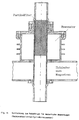
- a preferred arrangement is shown in FIG. 4.
- a central circular aperture plate which is provided in each of the two end faces, serves both to excite the resonator and to guide the exhaust gas. The position and the dimensioning of the coupling hole are decisive for the performance adjustment.
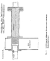
- the sample body was positioned in an R26 rectangular waveguide operated openly to demonstrate the principle of action and exposed to the microwave field of a 2.46 GHZ magnetron.
- the honeycom specimen was flowed through with a gas mixture consisting of approx. 8% oxygen and approx. 92% nitrogen.
- the microwave spring was connected spontaneously after the magnetic current was delivered. At the same time, soot ignition is observed spontaneously (see FIG. 2).
- 3 and 4 show devices that can be used for process demonstration using a diesel engine.
- a 300 cm3 single-cylinder direct injection engine with a maximum shaft output of 4.2 kWatt at 3000 mm ⁇ 1 speed was used.
- Load variations of the machine can be implemented via a shaft-coupled single-phase AC generator with an electronically variable load.
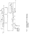
- FIG. 5 shows a simplified process flow diagram of the experimental analysis, which is equipped with a complex exhaust gas analysis (on-line) (Fourier transform infrared spectroscopy, infrared absorption spectroscopy, chemiluminescence).
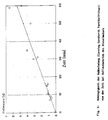
- FIG 6 shows an example of the dependency of the filter loading on the loading time for full load conditions of the diesel engine.
- the filter load can be correlated in a defined manner to the respective exhaust back pressure (filter stand pressure) in certain operating states of the machine.
- the measurement of the filter differential pressure is a very important parameter for process control of the Mw-induced particle erosion.
- thermocouples In the experiments to demonstrate the process, the temperature profile in the particle filter and the filter inlet and outlet temperatures were also determined (PT 100 thermocouples).
- the composition of the exhaust gas (on-line) before and after the particle filter was also determined.
- FIG. 7 shows an experimental diagram of a particle filter loaded in full-load operation after the machine power has been reduced to idle operation and starting the Mw performance.
- the rapid rise in temperature in the filter illustrates the immediate start of soot oxidation (measurement of the radiation temperature of the soot layer).
- the successive erosion of the soot layer can be determined from the differential pressure curve (o).
- FIG. 1 The basic principle of operation (FIG. 1) could thus be transferred to a technical unit.
- up to approx. 100 loading / burn-up cycles were run with a filter without the filter being damaged.
Landscapes
- Engineering & Computer Science (AREA)
- Chemical & Material Sciences (AREA)
- Combustion & Propulsion (AREA)
- Mechanical Engineering (AREA)
- General Engineering & Computer Science (AREA)
- Physics & Mathematics (AREA)
- Electromagnetism (AREA)
- Processes For Solid Components From Exhaust (AREA)
Applications Claiming Priority (2)
| Application Number | Priority Date | Filing Date | Title |
|---|---|---|---|
| DE4321363 | 1993-06-26 | ||
| DE19934321363 DE4321363A1 (de) | 1993-06-26 | 1993-06-26 | Verfahren und Vorrichtung zum Abbrand von Ruß auf keramischen Diesel-Partikelfiltern |
Publications (1)
| Publication Number | Publication Date |
|---|---|
| EP0635625A1 true EP0635625A1 (fr) | 1995-01-25 |
Family
ID=6491349
Family Applications (1)
| Application Number | Title | Priority Date | Filing Date |
|---|---|---|---|
| EP94105211A Withdrawn EP0635625A1 (fr) | 1993-06-26 | 1994-04-02 | Méthode et appareil d'incinération de la suie d'un filtre pour particules solides d'un moteur diesel |
Country Status (2)
| Country | Link |
|---|---|
| EP (1) | EP0635625A1 (fr) |
| DE (1) | DE4321363A1 (fr) |
Cited By (5)
| Publication number | Priority date | Publication date | Assignee | Title |
|---|---|---|---|---|
| WO2002042615A1 (fr) | 2000-11-21 | 2002-05-30 | Siemens Aktiengesellschaft | Procede de reduction d'emissions de particules carbonees de moteurs diesel et dispositif correspondant |
| EP1304456A1 (fr) | 2001-10-17 | 2003-04-23 | Universiteit van Amsterdam | Filtre à particules régénérable et méthode de régénération d'un filtre à particules |
| DE10057862C5 (de) * | 2000-11-21 | 2004-05-06 | Siemens Ag | Verfahren zur Verminderung kohlenstoffhaltiger Partikelemissionen von Dieselmotoren und zugehörige Anordnung |
| EP1541819A1 (fr) * | 2003-12-12 | 2005-06-15 | Nederlandse Organisatie voor toegepast-natuurwetenschappelijk onderzoek TNO | Filtre à particules diesel régénéré par micro-ondes |
| US7931727B2 (en) | 2007-09-17 | 2011-04-26 | Gm Global Technology Operations, Inc. | Microwave mode shifting antenna system for regenerating particulate filters |
Families Citing this family (1)
| Publication number | Priority date | Publication date | Assignee | Title |
|---|---|---|---|---|
| DE102006044893B4 (de) * | 2006-09-22 | 2011-06-30 | GM Global Technology Operations LLC, ( n. d. Ges. d. Staates Delaware ), Mich. | Steuerungssystem für Mikrowellenregeneration für einen Dieselpartikelfilter |
Citations (5)
| Publication number | Priority date | Publication date | Assignee | Title |
|---|---|---|---|---|
| EP0212396A2 (fr) * | 1985-08-08 | 1987-03-04 | Bayerische Motoren Werke Aktiengesellschaft, Patentabteilung AJ-3 | Dispositif pour éliminer la suie ou autres produits semblables des gaz d'échappement de moteurs à combustion interne |
| EP0221805A1 (fr) * | 1985-10-11 | 1987-05-13 | Regie Nationale Des Usines Renault | Procédé de traitement des particules carbonées contenues dans des gaz en circulation, notamment dans les gaz d'échappement de moteurs à allumage par compression |
| EP0443625A1 (fr) * | 1990-02-23 | 1991-08-28 | Matsushita Electric Industrial Co., Ltd. | Elément filtrant et appareil pour le traitement des effluents gazeux |
| US5074112A (en) * | 1990-02-21 | 1991-12-24 | Atomic Energy Of Canada Limited | Microwave diesel scrubber assembly |
| JPH04301124A (ja) * | 1991-03-29 | 1992-10-23 | Matsushita Electric Ind Co Ltd | 内燃機関用フィルタ再生装置 |
-
1993
- 1993-06-26 DE DE19934321363 patent/DE4321363A1/de not_active Withdrawn
-
1994
- 1994-04-02 EP EP94105211A patent/EP0635625A1/fr not_active Withdrawn
Patent Citations (5)
| Publication number | Priority date | Publication date | Assignee | Title |
|---|---|---|---|---|
| EP0212396A2 (fr) * | 1985-08-08 | 1987-03-04 | Bayerische Motoren Werke Aktiengesellschaft, Patentabteilung AJ-3 | Dispositif pour éliminer la suie ou autres produits semblables des gaz d'échappement de moteurs à combustion interne |
| EP0221805A1 (fr) * | 1985-10-11 | 1987-05-13 | Regie Nationale Des Usines Renault | Procédé de traitement des particules carbonées contenues dans des gaz en circulation, notamment dans les gaz d'échappement de moteurs à allumage par compression |
| US5074112A (en) * | 1990-02-21 | 1991-12-24 | Atomic Energy Of Canada Limited | Microwave diesel scrubber assembly |
| EP0443625A1 (fr) * | 1990-02-23 | 1991-08-28 | Matsushita Electric Industrial Co., Ltd. | Elément filtrant et appareil pour le traitement des effluents gazeux |
| JPH04301124A (ja) * | 1991-03-29 | 1992-10-23 | Matsushita Electric Ind Co Ltd | 内燃機関用フィルタ再生装置 |
Non-Patent Citations (1)
| Title |
|---|
| PATENT ABSTRACTS OF JAPAN vol. 17, no. 117 (M - 1378) 11 March 1993 (1993-03-11) * |
Cited By (7)
| Publication number | Priority date | Publication date | Assignee | Title |
|---|---|---|---|---|
| WO2002042615A1 (fr) | 2000-11-21 | 2002-05-30 | Siemens Aktiengesellschaft | Procede de reduction d'emissions de particules carbonees de moteurs diesel et dispositif correspondant |
| DE10057862C5 (de) * | 2000-11-21 | 2004-05-06 | Siemens Ag | Verfahren zur Verminderung kohlenstoffhaltiger Partikelemissionen von Dieselmotoren und zugehörige Anordnung |
| US6938409B2 (en) | 2000-11-21 | 2005-09-06 | Siemens Aktiengesellschaft | Method for reducing particle emissions containing carbon of diesel motors and corresponding system |
| EP1304456A1 (fr) | 2001-10-17 | 2003-04-23 | Universiteit van Amsterdam | Filtre à particules régénérable et méthode de régénération d'un filtre à particules |
| EP1541819A1 (fr) * | 2003-12-12 | 2005-06-15 | Nederlandse Organisatie voor toegepast-natuurwetenschappelijk onderzoek TNO | Filtre à particules diesel régénéré par micro-ondes |
| WO2005056989A1 (fr) * | 2003-12-12 | 2005-06-23 | Nederlandse Organisatie Voor Toegepast- Natuurwetenschappelijk Onderzoek Tno | Filtre a suies autonettoyant par combustion destine a un moteur a combustion interne |
| US7931727B2 (en) | 2007-09-17 | 2011-04-26 | Gm Global Technology Operations, Inc. | Microwave mode shifting antenna system for regenerating particulate filters |
Also Published As
| Publication number | Publication date |
|---|---|
| DE4321363A1 (de) | 1995-01-05 |
Similar Documents
| Publication | Publication Date | Title |
|---|---|---|
| DE69422833T2 (de) | Verbesserter partikelfilter und system und verfahren zu seiner reinigung | |
| DE60316163T2 (de) | Abgasbehandlungsvorrichtung | |
| DE69800838T2 (de) | Behandlung von abgasen | |
| DE69904623T2 (de) | Anordnung und verfahren zur reinigung von abgasen | |
| EP1212521B1 (fr) | Dispositif dote d'un element chauffant et destine a l'epuration des gaz d'echappement | |
| DE69417861T2 (de) | Honigwabenheizgerät | |
| DE69401133T2 (de) | Regenerierungsvorrichtung eines Filters für eine Brennkraftmaschine | |
| EP1697634B1 (fr) | Procede pour realiser l'allumage de la combustion d'un carburant dans une chambre de combustion d'un moteur, dispositif associe, et moteur | |
| EP3686405B1 (fr) | Élément chauffant de gaz d'échappement | |
| DE3504737C2 (fr) | ||
| DE102011076558A1 (de) | Abgasreinigungssystem für brennkraftmaschine | |
| EP1425497B1 (fr) | Dispositif et procede de post-traitement de gaz d'echappement | |
| EP0237824A1 (fr) | Procédé et dispositif pour la régénération de systèmes filtrant des particules | |
| DE102013207415A1 (de) | Filtersubstrat, das einen Dreiwegekatalysator umfasst | |
| EP0597206B1 (fr) | Procédé de réduction des particules de suie dans des courants de gaz d'échappement | |
| DE19513250A1 (de) | Verfahren und Vorrichtung zur kontinuierlichen Entfernung von Stickoxiden in Abgasen von Verbrennungsmaschinen | |
| DE10332606B4 (de) | Mikrowellenheizung mit selbst bewirkter Modenverwirbelung für eine Partikelfalle | |
| DE60000510T2 (de) | Plasmaunterstützte gasbehandlung | |
| DE10057862C5 (de) | Verfahren zur Verminderung kohlenstoffhaltiger Partikelemissionen von Dieselmotoren und zugehörige Anordnung | |
| DE3528445A1 (de) | Vorrichtung und verfahren zum beseitigen von russ o.dgl. aus den abgasen einer brennkraftmaschine | |
| DE19518970C1 (de) | Verfahren und Vorrichtung zur Behandlung von Abgas | |
| DE4321363A1 (de) | Verfahren und Vorrichtung zum Abbrand von Ruß auf keramischen Diesel-Partikelfiltern | |
| DE69414817T2 (de) | Honigwabenheizgerät | |
| DE60314220T2 (de) | Verfahren zur Verminderung des Partikelgehaltes der Abgase eines Magerverbrennungsmotors oder dergleichen | |
| DE60210557T2 (de) | Vorrichtung zur Abgasbehandlung einer Brennkraftmaschine |
Legal Events
| Date | Code | Title | Description |
|---|---|---|---|
| PUAI | Public reference made under article 153(3) epc to a published international application that has entered the european phase |
Free format text: ORIGINAL CODE: 0009012 |
|
| AK | Designated contracting states |
Kind code of ref document: A1 Designated state(s): DE FR GB |
|
| 17P | Request for examination filed |
Effective date: 19950303 |
|
| 17Q | First examination report despatched |
Effective date: 19951220 |
|
| STAA | Information on the status of an ep patent application or granted ep patent |
Free format text: STATUS: THE APPLICATION IS DEEMED TO BE WITHDRAWN |
|
| 18D | Application deemed to be withdrawn |
Effective date: 19970319 |