EP0635671A1 - Sicherheitsschlauch - Google Patents
Sicherheitsschlauch Download PDFInfo
- Publication number
- EP0635671A1 EP0635671A1 EP94109417A EP94109417A EP0635671A1 EP 0635671 A1 EP0635671 A1 EP 0635671A1 EP 94109417 A EP94109417 A EP 94109417A EP 94109417 A EP94109417 A EP 94109417A EP 0635671 A1 EP0635671 A1 EP 0635671A1
- Authority
- EP
- European Patent Office
- Prior art keywords
- hose
- sleeve
- rope
- traction means
- hose according
- Prior art date
- Legal status (The legal status is an assumption and is not a legal conclusion. Google has not performed a legal analysis and makes no representation as to the accuracy of the status listed.)
- Granted
Links
- 230000001681 protective effect Effects 0.000 claims abstract description 8
- 229920003023 plastic Polymers 0.000 claims abstract description 4
- 239000004033 plastic Substances 0.000 claims abstract description 4
- 239000000463 material Substances 0.000 claims description 4
- 239000000853 adhesive Substances 0.000 claims description 3
- 230000001070 adhesive effect Effects 0.000 claims description 3
- 238000004073 vulcanization Methods 0.000 claims description 3
- 229910000831 Steel Inorganic materials 0.000 claims description 2
- 239000004744 fabric Substances 0.000 claims description 2
- 229920002457 flexible plastic Polymers 0.000 claims description 2
- 239000010959 steel Substances 0.000 claims description 2
- 239000004753 textile Substances 0.000 claims description 2
- 230000006378 damage Effects 0.000 description 5
- 208000027418 Wounds and injury Diseases 0.000 description 3
- 230000009172 bursting Effects 0.000 description 3
- 208000014674 injury Diseases 0.000 description 3
- 238000004519 manufacturing process Methods 0.000 description 3
- 238000010276 construction Methods 0.000 description 2
- 230000035882 stress Effects 0.000 description 2
- 230000007704 transition Effects 0.000 description 2
- 230000032683 aging Effects 0.000 description 1
- 210000000078 claw Anatomy 0.000 description 1
- 230000006835 compression Effects 0.000 description 1
- 238000007906 compression Methods 0.000 description 1
- 230000007547 defect Effects 0.000 description 1
- 239000000835 fiber Substances 0.000 description 1
- 238000009434 installation Methods 0.000 description 1
- 239000007788 liquid Substances 0.000 description 1
- 239000002184 metal Substances 0.000 description 1
- 238000009420 retrofitting Methods 0.000 description 1
- 238000000926 separation method Methods 0.000 description 1
- 230000003313 weakening effect Effects 0.000 description 1
Images


Classifications
-
- F—MECHANICAL ENGINEERING; LIGHTING; HEATING; WEAPONS; BLASTING
- F16—ENGINEERING ELEMENTS AND UNITS; GENERAL MEASURES FOR PRODUCING AND MAINTAINING EFFECTIVE FUNCTIONING OF MACHINES OR INSTALLATIONS; THERMAL INSULATION IN GENERAL
- F16L—PIPES; JOINTS OR FITTINGS FOR PIPES; SUPPORTS FOR PIPES, CABLES OR PROTECTIVE TUBING; MEANS FOR THERMAL INSULATION IN GENERAL
- F16L55/00—Devices or appurtenances for use in, or in connection with, pipes or pipe systems
- F16L55/005—Devices restraining ruptured tubes from whipping
Definitions
- the invention relates to a safety hose, in particular a high-pressure hose, which is surrounded by a flexible protective sheath, which is fixed to an abutment by an end-face traction means.
- Hose lines pressurized with liquid or gaseous media can, for example, burst or leak due to material fatigue or impermissibly high stresses caused by exceeding the maximum pressure limits.
- the fitting ie the screw connection that enables attachment to another hose, a compressor or a pressurized device, with defects primarily at the transition from the flexible hose to the rigid, positive or non-positive connection the hose connected compression sleeve of the valve arise.
- a setting i.e.
- the cable pulling stockings previously used as a safety precaution in the event of a hose bursting consist of a flexible, mesh-like metal braid which is pulled over the hose and fastened on the end face by means of traction means to a counter bearing, usually the adjacent device or hose.
- the cable pulling stocking is compressed in the axial direction before assembly, so that its inside diameter increases and is pushed over the hose.
- the cable pulling stocking expands in this direction, so that it contracts radially and engages and claws in the hose.
- the pressurized medium can escape, but due to the fixation by means of the cable pulling stocking, the movements of the hose which are to be classified as particularly dangerous due to the reaction forces are prevented.
- the invention is based on the problem of designing a hose which is particularly suitable for high-pressure application in such a way that work safety is increased and hooking or fanning of the bursting protection against obstacles is prevented.
- the object is achieved in that the protective sleeve is an elastic, hollow cylindrical sleeve, preferably made of rubber or plastic, and is attached to the entire surface of the hose, and that a rope runs inside the sleeve, usually between the sleeve and the hose, in the axial direction and at the ends is attached to the traction mechanism.
- the main idea of the invention is to replace the cable pulling stocking with a flexible rubber or plastic sleeve connected to the entire surface of the hose, to insert a rope inside the sleeve in the axial direction and to connect it to a counter bearing by means of traction means.
- the assembly is carried out as with conventional burst-protected hoses, ie after connecting the valve to a device or to an extension hose the end faces of the ropes are fixed by means of traction on the counter bearing, eg the neighboring device or hose, whereupon pressure can be applied.
- the function of the burst protection is as follows: If the hose comes loose from its attachment in the fitting or breaks near the press sleeve - the majority of hose breaks occur at these points - the pressurized medium escapes, but the reaction forces that run against the direction of flow are eliminated by the Transfer the hose over the cuff onto the rope and over the traction mechanism to the thrust bearing, so that the hose moves a short distance until the traction mechanism is tightened. After the hose bursts in its central area enclosed by the cuff, the reaction forces are also transmitted from the hose via the cuff to the rope, so that a complete break, ie a separation into two hose parts at the bursting point, is prevented.
- the force fit and the strength of the seat of the protective cover are at least equivalent to or even superior to that of a new cable pulling stocking.
- the advantages of the invention consist primarily in the fact that the use of an elastic sleeve and the avoidance of point loads mean that there are no longer any signs of fatigue in the protective cover and that they are subject to wear and tear smooth surface cannot get caught on obstacles or fanned out, so that the maximum attainable operating time and the occupational safety of the operating personnel is decisively improved. Furthermore, in addition to the reduced production costs, it can be considered advantageous that retrofitting of existing hoses is easily possible and that the smooth surface makes laying and pulling the hoses more comfortable, so that hoses with a burst protection device are used more frequently than before.
- the task of the connection between the hose and the cuff is to create a permanent, heavy-duty fixation. Because of their ease of attachment, vulcanization or adhesive bonds are preferred.
- the end of the rope advantageously has the shape of a loop or eyelet, since a detachable connection to the traction means, which can be acted upon with high forces, is possible.
- the ropes are preferably distributed equidistantly over the circumference of the hose.
- the high-pressure hose (1) shown in FIG. 1 is connected on its end face to a fitting (2) in a force-locking or form-fitting manner via a press sleeve (3). Due to material fatigue of the hose (1), the fitting (2) or the press sleeve (3), the hose (1) can come loose from the press sleeve (3) after a long period of operation or at the transition between the hose (1) and the press sleeve ( 3) burst, with the result that the hose (1), which is of massive construction due to the high loads, tears, moves against the direction of flow of the pressurized medium and can cause considerable injuries to the operating personnel or damage in the vicinity of positioned objects.
- a hollow cylindrical sleeve (4) is fastened over the entire surface of the hose, preferably by means of a vulcanization or adhesive connection, and between the hose (1) and the sleeve (4) there are two loops (7) running in the axial direction on the front side ) provided ropes (5).
- Flexible traction means (6) provided on the end face with snap hooks (8) are used for attachment to a counterbearing, which can be a further hose (1) or a device, for example a compressor.
- the reaction forces are transferred to the thrust bearing via the sleeve (4), the rope (5) and the traction means (6), so that the pressurized medium emerges, the hose (1) only moves until the traction mechanism (6) is tightened. If a hose break occurs in the middle area enclosed by the sleeve (4), the rope (5) prevents the hose (1) from separating into two parts, so that in this case too there is no danger to persons or in the vicinity positioned objects occurs.
- the fitting (2) of the high-pressure hose (1) shown in FIG. 2 is mounted on a flange (9), two traction means (6) connected to a rope (5) laid between the hose (1) and the sleeve (4) via carabiners (8) connect with eyelets mounted on the flange (9).
- the ropes (5) of a high-pressure hose (1) are each connected to the ropes (5) of a second hose (1 ') by means of a traction device (6) and the fittings (2) of the hoses (1) by means of a threaded sleeve ( 10) attached to each other.
- the result is a safety hose that is characterized by reduced production costs, an increased service life, improved occupational safety and easy installation.
Landscapes
- Engineering & Computer Science (AREA)
- General Engineering & Computer Science (AREA)
- Mechanical Engineering (AREA)
- Rigid Pipes And Flexible Pipes (AREA)
- Joints That Cut Off Fluids, And Hose Joints (AREA)
Abstract
Description
- Die Erfindung bezieht sich auf einen Sicherheitsschlauch, insbesondere Hochdruckschlauch, der von einer flexiblen, durch ein stirnseitiges Zugmittel an einem Gegenlager fixierten Schutzhülle umgeben ist.
- Mit flüssigen oder gasförmigen Medien druckbeaufschlagte Schlauchleitungen können beispielsweise durch Materialermüdung oder unzulässig hohe, durch Überschreitung der maximalen Grenzwerte der Drücke bedingte Beanspruchungen bersten oder Leckagen bekommen. Dabei treten in erster Linie Brüche der Schlauchleitung an den Verbindungsstellen mit der Armatur, d.h. der eine Befestigung an einem anderen Schlauch, einem Kompressor oder einem druckbeaufschlagten Gerät ermöglichenden Schraubverbindung auf, wobei Defekte vornehmlich am Übergang vom flexiblen Schlauch zur starren, form- oder kraftschlüssig mit dem Schlauch verbundenen Preßhülse der Armatur entstehen. Neben Überlastungen und Alterungserscheinungen des Schlauches oder der Armatur kann auch ein Setzen, also ein Nachlassen der Festigkeit der Verbindung mit der Armatur oder eine durch unsachgemäße Behandlung bedingte Zug- und Knickbeanspruchung der Verbindungsstellen einen Schlauchbruch begünstigen. Aufgrund der hohen Drücke und Volumendurchsätze entstehen durch einen geborstenen Schlauch häufig schwere Verletzungen sich in der Nähe aufhaltenden Personals sowie Beschädigungen benachbarter Gegenstände und Geräte, wobei das Gefährdungspotential nicht nur vom austretenden Medium, sondern auch von den schweren, sich infolge der Reaktionskräfte entgegen der Flußrichtung des Mediums mit hoher kinetischer Energie bewegenden Schlauchenden ausgeht.
- Die bisher als Sicherheitsvorkehrung für den Fall eines Schlauchberstens eingesetzten Kabelziehstrümpfe bestehen aus einem flexiblen, netzartigen Metallgeflecht, das über den Schlauch gezogen und stirnseitig durch Zugmittel an einem Gegenlager, gewöhnlich dem benachbarten Gerät oder Schlauch befestigt ist. Zur sicheren Fixierung wird der Kabelziehstrumpf vor der Montage in axialer Rich-tung zusammengepreßt, so daß sich sein Innendurchmesser vergrößert und über den Schlauch geschoben. Mit Beendigung des axialen Druckes dehnt sich der Kabelziehstrumpf in dieser Richtung aus, so daß er sich radial zusammenzieht und in den Schlauch eingreift und verkrallt. Nach einem Schlauchbruch kann zwar das druckbeaufschlagte Medium austreten, jedoch sind aufgrund der Fixierung mittels des Kabelziehstrumpfes die durch die Reaktionskräfte bedingten, als besonders gefährlich einzustufenden Bewegungen des Schlauchs unterbunden.
- Bei den bekannten Kabelziehstrümpfen ist neben den hohen Gestehungskosten als nachteilig anzusehen, daß sie bei einer Druckbeaufschlagung des Schlauches über ihre Elastizitätsgrenze hinaus gedehnt werden, so daß nach mehreren Beaufschlagungen Ermüdungsbrüche der einzelnen Fasern auftreten und der Schutz verloren geht. Durch die netzartige Struktur kann sich der Kabelziehstrumpf an Hindernissen wie z.B. Baugerüsten verhaken oder, falls er daran vorbeigezogen wird, aufspleißen, und durch die überstehenden, spitzen Enden entsteht ein weiteres Verletzungsrisiko für das Bedienungspersonal.
- Ausgehend vom Stande der Technik liegt der Erfindung das Problem zugrunde, einen insbesondere zur Hochdruckbeaufschlagung geeigneten Schlauch so zu gestalten, daß die Arbeitssicherheit vergrößert und ein Verhaken oder Aufspleißen des Berstschutzes an Hindernissen unterbunden ist.
- Erfindungsgemäß wird die Aufgabe dadurch gelöst, daß die Schutzhülle eine elastische, hohlzylindrische Manschette vorzugsweise aus Gummi oder Kunststoff und vollflächig am Schlauch befestigt ist, und daß ein Seil innerhalb der Manschette, in der Regel zwischen der Manschette und dem Schlauch in axialer Richtung verläuft und endseitig am Zugmittel befestigt ist.
- Der Kerngedanke der Erfindung besteht darin, den Kabelziehstrumpf durch eine vollflächig mit dem Schlauch verbundene, flexible Manschette aus Gummi oder Kunststoff zu ersetzen, ein Seil innerhalb der Manschette in axialer Richtung einzubringen und über Zugmittel mit einem Gegenlager zu verbinden. Die Montage erfolgt wie bei konventionellen berstgeschützten Schläuchen, d.h. nach dem Anschluß der Armatur an einem Gerät oder an einem Verlängerungsschlauch werden die Stirnseiten der Seile durch Zugmittel am Gegenlager, z.B. dem benachbarten Gerät oder schlauch festgelegt, woraufhin eine Druckbeaufschlagung erfolgen kann. Die Funktionsweise des Berstschutzes ist wie folgt: Falls sich der Schlauch aus seiner Befestigung in der Armatur löst oder nahe der Preßhülse bricht - die Mehrzahl der Schlauchbrüche erfolgt an diesen Stellen - tritt zwar das druckbeaufschlagte Medium aus, jedoch werden die entgegen der Strömungsrichtung laufenden Reaktionskräfte vom Schlauch über die Manschette auf das Seil und über das Zugmittel auf das Gegenlager übertragen, so daß sich der Schlauch um eine kurze Wegstrecke so weit verschiebt, bis die Zugmittel gestrafft sind. Nach einem Bersten des Schlauches in seinem mittleren, von der Manschette umschlossenen Bereich werden die Reaktionskräfte ebenfalls vom Schlauch über die Manschette auf das Seil übertragen, so daß ein vollständiger Bruch, d.h. eine Trennung in zwei Schlauchteile an der Berststelle unterbunden ist. Aufgrund der vollflächigen Befestigung der Manschette am Schlauch und der Montage des Seils zwischen der Manschette und dem Schlauch ist der Kraftschluß und die Festigkeit des Sitzes der Schutzhülle mit der eines neuwertigen Kabelziehstrumpfes zumindest gleichwertig oder ihr sogar überlegen.
- Die Vorteile der Erfindung bestehen vornehmlich darin, daß durch die Verwendung einer elastischen Manschette und durch das Vermeiden punktueller Belastungen keine Ermüdungserscheinungen der Schutzhülle mehr auftreten und daß sie sich aufgrund ihrer glatten Oberfläche nicht an Hindernissen verhaken oder aufspleißen kann, so daß die maximal erreichbare Betriebszeit und die Arbeitssicherheit des Bedienungspersonals entscheidend verbessert ist. Weiterhin ist neben den reduzierten Gestehungskosten als vorteilhaft anzusehen, daß eine Nachrüstung bereits vorhandener Schläuche leicht möglich ist und daß die glatte Oberfläche das Verlegen und Ziehen der Schläuche komfortabler gestaltet, so daß Schläuche mit einer Berstschutzeinrichtung häufiger als bisher eingesetzt werden.
- Die Aufgabe der Verbindung zwischen dem Schlauch und der Manschette besteht darin, eine dauerhafte, hochbelastbare Fixierung herzustellen. Aufgrund ihrer leichten Anbringbarkeit sind Vulkanisations- oder Klebeverbindungen bevorzugt.
- Das Ende des Seils weist vorteilhafterweise die Form einer Schlaufe oder Öse auf, da eine lösbare, jedoch mit hohen Kräften beaufschlagbare Verbindung mit dem Zugmittel möglich ist.
- Der Vorteil eines endlosen Seils besteht darin, daß die Stirnseiten in Form einer Schlaufe oder Öse verlegt werden können, wobei keine einen hohen Raumbedarf aufweisende, möglicherweise aufspleißende oder nicht hinreichend stabile Verbindung des Seilendes mit dem übrigen Seil erforderlich ist.
- Als Zugmittel sind Stahlseile vorgeschlagen, wobei die Verbindung mit dem Seil und/oder dem Gegenlager vorzugsweise durch Karabinerhaken erfolgt. Derartige Zugmittel werden für die Befestigung der bekannten Kabelziehstrümpfe verwendet und sind daher gewöhnlich bereits vorhanden.
- Weiterhin ist empfohlen, ein Seil aus hochfestem, flexiblen Kunststoff-Textilmaterial, vorzugsweise aus kevlar-verstärktem Gewebe zu verwenden, das sich durch hohe Festigkeit bei geringer Masse auszeichnet.
- Um die Sicherungseinrichtung auch höchsten Belastungen unterwerfen zu können, ist bevorzugt, mindestens zwei Seile zwischen Manschette und Schlauch anzuordnen, so daß der Schlauch auch fixiert bleibt, falls ein Seil reißen oder brechen sollte. Um die Reaktionskräfte gleichmäßig zu verteilen, sind die Seile vorzugsweise äquidistant über den Umfang des Schlauchs verteilt.
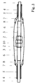
- Weitere Einzelheiten, Merkmale und Vorteile der Erfindung lassen sich dem nachfolgenden Beschreibungsteil entnehmen, in dem anhand der Zeichnungen ein Ausführungsbeispiel der Erfindung näher erläutert wird. Sie zeigen in schematischer Darstellung in
- Figur 1
- den Aufbau eines Sicherheitsschlauches für Hochdruckbeaufschlagung
- Figur 2
- einen an einem Flansch montierten Sicherheitsschlauch
- Figur 3
- einen an einem Verlängerungsschlauch montierten Sicherheitsschlauch
- Der in Figur 1 dargestellte Hochdruckschlauch (1) ist an seiner Stirnseite mit einer Armatur (2) kraft- oder formschlüssig über eine Preßhülse (3) verbunden. Durch Materialermüdungen des Schlauches (1), der Armatur (2) oder der Preßhülse (3) kann sich nach einer längeren Betriebszeit der Schlauch (1) aus der Preßhülse (3) lösen oder am Übergang zwischen dem Schlauch (1) und der Preßhülse (3) bersten, mit dem Ergebnis, daß der wegen der hohen Belastungen massiv ausgeführte Schlauch (1) abreißt, sich entgegen der Flußrichtung des druckbeaufschlagten Mediums bewegt und erhebliche Verletzungen des Bedienungspersonals oder Beschädigungen in der Nähe positionierter Gegenstände bedingen kann. Um das Gefährdungspotential zu reduzieren, ist vollflächig um den Schlauch eine hohlzylindrische Manschette (4) vorzugsweise durch eine Vulkanisations- oder Klebeverbindung befestigt und zwischen dem Schlauch (1) und der Manschette (4) sind zwei in axialer Richtung verlaufende, stirnseitig mit Schlaufen (7) versehene Seile (5) montiert. Flexible, stirnseitig mit Karabinerhaken (8) versehene Zugmittel (6) dienen der Befestigung an einem Gegenlager, das ein weiterer Schlauch (1) oder ein Gerät, beispielsweise ein Kompressor sein kann. Falls der Schlauch (1) besten sollte, werden die Reaktionskräfte über die Manschette (4), das Seil (5) und das Zugmittel (6) auf das Gegenlager übertragen, so daß zwar das druckbeaufschlagte Medium austritt, der Schlauch (1) sich jedoch nur soweit bewegt, bis das Zugmittel (6) gestrafft ist. Falls ein Schlauchbruch in dem von der Manschette (4) umschlossenen, mittleren Bereich auftritt, verhindert das Seil (5), daß sich der Schlauch (1) in zwei Teile auftrennt, so daß auch in diesem Fall keine Gefährdung von Personen oder in der Nähe positionierten Gegenständen auftritt.
- Die Armatur (2) des in Figur 2 dargestellten Hochdruckschlauchs (1) ist an einem Flansch (9) montiert, wobei zwei mit je einem zwischen Schlauch (1) und Manschette (4) verlegten Seil (5) verbundene Zugmittel (6) über Karabinerhaken (8) mit am Flansch (9) montierten Ösen in Verbindung stehen.
- In Figur 3 sind die Seile (5) eines Hochdruckschlauchs (1) über je ein Zugmittel (6) mit den Seilen (5) eines zweiten Schlauches (1') verbunden und die Armaturen (2) der Schläuche (1) mittels einer Gewindemuffe (10) aneinander befestigt.
- Im Ergebnis erhält man einen Sicherheitsschlauch, der sich durch reduzierte Gestehungskosten, eine erhöhte Lebensdauer, verbesserte Arbeitssicherheit und durch leichte Verlegbarkeit auszeichnet.
Claims (8)
- Sicherheitsschlauch, insbesondere Hochdruckschlauch, der von einer flexiblen, durch ein stirnseitiges Zugmittel an einem Gegenlager fixierten Schutzhülle umgeben ist, dadurch gekennzeichnet, daß die Schutzhülle eine elastische, hohlzylindrische Manschette (4) vorzugsweise aus Gummi oder Kunststoff und vollflächig am Schlauch (1) befestigt ist, und
daß ein Seil (5) innerhalb der Manschette (4), in der Regel zwischen der Manschette (4) und dem Schlauch (1) in axialer Richtung verläuft und endseitig am Zugmittel (6) befestigt ist. - Schlauch nach Anspruch 1, dadurch gekennzeichnet, daß die Manschette (4) durch eine Vulkanisations- oder Klebeverbindung am Schlauch (1) fixiert ist.
- Schlauch nach Anspruch 1 oder 2, dadurch gekennzeichnet, daß das Ende des Seils (5) die Form einer Schlaufe oder einer Öse aufweist.
- Schlauch nach einem der Ansprüche 1 bis 3, dadurch gekennzeichnet, daß das Seil (5) endlos ist.
- Schlauch nach einem der Ansprüche 1 bis 4, dadurch gekennzeichnet, daß das Zugmittel (6) ein Stahlseil ist.
- Schlauch nach einem der Ansprüche 1 bis 5, dadurch gekennzeichnet, daß das Zugmittel (6) durch Karabinerhaken (8) mit dem Seil (5) und/oder dem Gegenlager verbunden ist.
- Schlauch nach einem der Ansprüche 1 bis 6, gekennzeichnet durch ein Seil (5) aus hochfestem, flexiblen Kunststoff-Textilmaterial, vorzugsweise aus kevlar-verstärktem Gewebe.
- Schlauch nach einem der Ansprüche 1 bis 7, gekennzeichnet durch mindestens zwei vorzugsweise äquidistant über den Umfang des Schlauchs (1) angeordnete Seile (5).
Applications Claiming Priority (2)
| Application Number | Priority Date | Filing Date | Title |
|---|---|---|---|
| DE4324943 | 1993-07-24 | ||
| DE4324943A DE4324943A1 (de) | 1993-07-24 | 1993-07-24 | Sicherheitsschlauch |
Publications (2)
| Publication Number | Publication Date |
|---|---|
| EP0635671A1 true EP0635671A1 (de) | 1995-01-25 |
| EP0635671B1 EP0635671B1 (de) | 1996-10-30 |
Family
ID=6493660
Family Applications (1)
| Application Number | Title | Priority Date | Filing Date |
|---|---|---|---|
| EP94109417A Expired - Lifetime EP0635671B1 (de) | 1993-07-24 | 1994-06-17 | Sicherheitsschlauch |
Country Status (3)
| Country | Link |
|---|---|
| EP (1) | EP0635671B1 (de) |
| AT (1) | ATE144821T1 (de) |
| DE (2) | DE4324943A1 (de) |
Cited By (1)
| Publication number | Priority date | Publication date | Assignee | Title |
|---|---|---|---|---|
| FR2801961A1 (fr) * | 1999-12-07 | 2001-06-08 | M R Ind | Dispositif de protection pour tuyaux hydrauliques et tuyaux equipes |
Families Citing this family (3)
| Publication number | Priority date | Publication date | Assignee | Title |
|---|---|---|---|---|
| DE29503167U1 (de) * | 1995-02-24 | 1995-04-13 | Stahlgruber Otto Gruber GmbH & Co, 81675 München | Sicherungsmanschette für Hochdruckschläuche und Pflaster zur Herstellung einer Sicherungsmanschette |
| DE112013000141A5 (de) | 2012-04-19 | 2014-06-26 | Buchen Umweltservice Gmbh | Hochdruckschlauch für eine Reinigungsvorrichtung und Reinigungsvorrichtung |
| DE102021105591B3 (de) | 2021-03-09 | 2022-05-25 | Uniflex - Hydraulik GmbH | Hydraulikeinheit |
Citations (3)
| Publication number | Priority date | Publication date | Assignee | Title |
|---|---|---|---|---|
| US2185741A (en) * | 1938-07-05 | 1940-01-02 | Lloyd F Sorg | Hose attachment |
| US3197240A (en) * | 1963-01-24 | 1965-07-27 | Colorado Fuel & Iron Corp | Safety device |
| US3813733A (en) * | 1973-02-16 | 1974-06-04 | I Flohr | Safety cable and band |
-
1993
- 1993-07-24 DE DE4324943A patent/DE4324943A1/de not_active Withdrawn
-
1994
- 1994-06-17 DE DE59400933T patent/DE59400933D1/de not_active Expired - Fee Related
- 1994-06-17 EP EP94109417A patent/EP0635671B1/de not_active Expired - Lifetime
- 1994-06-17 AT AT94109417T patent/ATE144821T1/de not_active IP Right Cessation
Patent Citations (3)
| Publication number | Priority date | Publication date | Assignee | Title |
|---|---|---|---|---|
| US2185741A (en) * | 1938-07-05 | 1940-01-02 | Lloyd F Sorg | Hose attachment |
| US3197240A (en) * | 1963-01-24 | 1965-07-27 | Colorado Fuel & Iron Corp | Safety device |
| US3813733A (en) * | 1973-02-16 | 1974-06-04 | I Flohr | Safety cable and band |
Cited By (2)
| Publication number | Priority date | Publication date | Assignee | Title |
|---|---|---|---|---|
| FR2801961A1 (fr) * | 1999-12-07 | 2001-06-08 | M R Ind | Dispositif de protection pour tuyaux hydrauliques et tuyaux equipes |
| WO2001042703A1 (fr) * | 1999-12-07 | 2001-06-14 | Mr Industries | Dispositif de protection pour tuyaux de transport de fluide sous pression |
Also Published As
| Publication number | Publication date |
|---|---|
| DE59400933D1 (de) | 1996-12-05 |
| ATE144821T1 (de) | 1996-11-15 |
| EP0635671B1 (de) | 1996-10-30 |
| DE4324943A1 (de) | 1995-01-26 |
Similar Documents
| Publication | Publication Date | Title |
|---|---|---|
| DE102010060981B3 (de) | Rohrflanschverbindung | |
| EP0639248B1 (de) | Seilendverbindung für ein kunststoffseil | |
| DE29906626U1 (de) | Betätigungseinrichtung | |
| DE60009162T2 (de) | Kausche für flexibles flachseil | |
| EP0778165B1 (de) | Zugmittel | |
| EP0635671B1 (de) | Sicherheitsschlauch | |
| DE102021105591B3 (de) | Hydraulikeinheit | |
| EP3938648B1 (de) | Flanschverbindung, windenergieanlage mit selbiger, und verfahren zur überwachung selbiger | |
| DE102018205891B3 (de) | Durch Fluidbeaufschlagung aktivierbare Betätigungseinrichtung mit Rastmechanismus | |
| EP2159325A1 (de) | Hebe- und Montagevorrichtung für Zugglieder von Bauwerken, Verwendung eines Abstützelements und Verwendung einer Vorrichtung sowie Verfahren zum Anbringen und Spannen eines Zugglieds | |
| AT509798B1 (de) | Modulare schlauchbrücke | |
| DE102009044807B4 (de) | Spannringsatz | |
| DE2740827A1 (de) | Elastische wellenkupplung | |
| DE29608853U1 (de) | Schlauch-Fangschlinge | |
| EP1686305A1 (de) | Einrichtung zum Ausgleich der Bewegung zweier miteinander druckdicht zu verbindender Rohre | |
| GB2305230A (en) | Safety lifeline shock absorber | |
| DE2159995A1 (de) | Seil mit unfallschutz | |
| DE102023123162B4 (de) | Kabelklemme | |
| CH363692A (de) | Nachgiebiger Abstandhalter für Freileitungen | |
| DE2616853C2 (de) | Befestigungsflansch an einem Gummischlauch | |
| DE3436951C2 (de) | Schlauchbefestigung mit einem gehäuseintegrierten außen zylindrischen Schlauchanschlußstutzen und einer Federklemme | |
| DE202004003544U1 (de) | Sicherungsseil | |
| DE202004007126U1 (de) | Seil zur Befestigung von Filtertüchern | |
| EP0795713A1 (de) | Sicherungsvorrichtung für Verbindungs- und Anschlussstellen von Hochdruckschläuchen | |
| DE2600270C2 (de) | Elastische Kupplung |
Legal Events
| Date | Code | Title | Description |
|---|---|---|---|
| PUAI | Public reference made under article 153(3) epc to a published international application that has entered the european phase |
Free format text: ORIGINAL CODE: 0009012 |
|
| AK | Designated contracting states |
Kind code of ref document: A1 Designated state(s): AT BE CH DE FR GB IT LI NL SE |
|
| 17P | Request for examination filed |
Effective date: 19950614 |
|
| GRAG | Despatch of communication of intention to grant |
Free format text: ORIGINAL CODE: EPIDOS AGRA |
|
| GRAH | Despatch of communication of intention to grant a patent |
Free format text: ORIGINAL CODE: EPIDOS IGRA |
|
| GRAH | Despatch of communication of intention to grant a patent |
Free format text: ORIGINAL CODE: EPIDOS IGRA |
|
| GRAH | Despatch of communication of intention to grant a patent |
Free format text: ORIGINAL CODE: EPIDOS IGRA |
|
| 17Q | First examination report despatched |
Effective date: 19951219 |
|
| GRAH | Despatch of communication of intention to grant a patent |
Free format text: ORIGINAL CODE: EPIDOS IGRA |
|
| GRAA | (expected) grant |
Free format text: ORIGINAL CODE: 0009210 |
|
| AK | Designated contracting states |
Kind code of ref document: B1 Designated state(s): AT BE CH DE FR GB IT LI NL SE |
|
| REF | Corresponds to: |
Ref document number: 144821 Country of ref document: AT Date of ref document: 19961115 Kind code of ref document: T |
|
| REF | Corresponds to: |
Ref document number: 59400933 Country of ref document: DE Date of ref document: 19961205 |
|
| ITF | It: translation for a ep patent filed | ||
| GBT | Gb: translation of ep patent filed (gb section 77(6)(a)/1977) |
Effective date: 19970107 |
|
| ET | Fr: translation filed | ||
| PG25 | Lapsed in a contracting state [announced via postgrant information from national office to epo] |
Ref country code: AT Free format text: LAPSE BECAUSE OF NON-PAYMENT OF DUE FEES Effective date: 19970617 |
|
| PG25 | Lapsed in a contracting state [announced via postgrant information from national office to epo] |
Ref country code: SE Effective date: 19970618 |
|
| PG25 | Lapsed in a contracting state [announced via postgrant information from national office to epo] |
Ref country code: LI Free format text: LAPSE BECAUSE OF NON-PAYMENT OF DUE FEES Effective date: 19970630 Ref country code: CH Free format text: LAPSE BECAUSE OF NON-PAYMENT OF DUE FEES Effective date: 19970630 Ref country code: BE Effective date: 19970630 |
|
| PLBE | No opposition filed within time limit |
Free format text: ORIGINAL CODE: 0009261 |
|
| STAA | Information on the status of an ep patent application or granted ep patent |
Free format text: STATUS: NO OPPOSITION FILED WITHIN TIME LIMIT |
|
| 26N | No opposition filed | ||
| BERE | Be: lapsed |
Owner name: WEIGEL BERND Effective date: 19970630 |
|
| REG | Reference to a national code |
Ref country code: CH Ref legal event code: PL |
|
| PG25 | Lapsed in a contracting state [announced via postgrant information from national office to epo] |
Ref country code: FR Free format text: LAPSE BECAUSE OF NON-PAYMENT OF DUE FEES Effective date: 19980227 |
|
| EUG | Se: european patent has lapsed |
Ref document number: 94109417.9 |
|
| REG | Reference to a national code |
Ref country code: FR Ref legal event code: ST |
|
| REG | Reference to a national code |
Ref country code: FR Ref legal event code: ST |
|
| PGFP | Annual fee paid to national office [announced via postgrant information from national office to epo] |
Ref country code: DE Payment date: 19980604 Year of fee payment: 5 |
|
| PG25 | Lapsed in a contracting state [announced via postgrant information from national office to epo] |
Ref country code: GB Free format text: LAPSE BECAUSE OF NON-PAYMENT OF DUE FEES Effective date: 19980617 |
|
| PG25 | Lapsed in a contracting state [announced via postgrant information from national office to epo] |
Ref country code: NL Free format text: LAPSE BECAUSE OF NON-PAYMENT OF DUE FEES Effective date: 19990101 |
|
| GBPC | Gb: european patent ceased through non-payment of renewal fee |
Effective date: 19980617 |
|
| NLV4 | Nl: lapsed or anulled due to non-payment of the annual fee |
Effective date: 19990101 |
|
| PG25 | Lapsed in a contracting state [announced via postgrant information from national office to epo] |
Ref country code: DE Free format text: LAPSE BECAUSE OF NON-PAYMENT OF DUE FEES Effective date: 20000503 |
|
| PG25 | Lapsed in a contracting state [announced via postgrant information from national office to epo] |
Ref country code: IT Free format text: LAPSE BECAUSE OF NON-PAYMENT OF DUE FEES;WARNING: LAPSES OF ITALIAN PATENTS WITH EFFECTIVE DATE BEFORE 2007 MAY HAVE OCCURRED AT ANY TIME BEFORE 2007. THE CORRECT EFFECTIVE DATE MAY BE DIFFERENT FROM THE ONE RECORDED. Effective date: 20050617 |