EP0635681B1 - Chambre de combustion à prémélange d'un rapport constant carburant/comburant et avec combustion dans une seule étappe - Google Patents
Chambre de combustion à prémélange d'un rapport constant carburant/comburant et avec combustion dans une seule étappe Download PDFInfo
- Publication number
- EP0635681B1 EP0635681B1 EP94109802A EP94109802A EP0635681B1 EP 0635681 B1 EP0635681 B1 EP 0635681B1 EP 94109802 A EP94109802 A EP 94109802A EP 94109802 A EP94109802 A EP 94109802A EP 0635681 B1 EP0635681 B1 EP 0635681B1
- Authority
- EP
- European Patent Office
- Prior art keywords
- fuel
- compressed air
- housing
- air
- venturi
- Prior art date
- Legal status (The legal status is an assumption and is not a legal conclusion. Google has not performed a legal analysis and makes no representation as to the accuracy of the status listed.)
- Expired - Lifetime
Links
Images

Classifications
-
- F—MECHANICAL ENGINEERING; LIGHTING; HEATING; WEAPONS; BLASTING
- F23—COMBUSTION APPARATUS; COMBUSTION PROCESSES
- F23R—GENERATING COMBUSTION PRODUCTS OF HIGH PRESSURE OR HIGH VELOCITY, e.g. GAS-TURBINE COMBUSTION CHAMBERS
- F23R3/00—Continuous combustion chambers using liquid or gaseous fuel
- F23R3/42—Continuous combustion chambers using liquid or gaseous fuel characterised by the arrangement or form of the flame tubes or combustion chambers
- F23R3/54—Reverse-flow combustion chambers
-
- F—MECHANICAL ENGINEERING; LIGHTING; HEATING; WEAPONS; BLASTING
- F02—COMBUSTION ENGINES; HOT-GAS OR COMBUSTION-PRODUCT ENGINE PLANTS
- F02C—GAS-TURBINE PLANTS; AIR INTAKES FOR JET-PROPULSION PLANTS; CONTROLLING FUEL SUPPLY IN AIR-BREATHING JET-PROPULSION PLANTS
- F02C9/00—Controlling gas-turbine plants; Controlling fuel supply in air- breathing jet-propulsion plants
- F02C9/48—Control of fuel supply conjointly with another control of the plant
- F02C9/50—Control of fuel supply conjointly with another control of the plant with control of working fluid flow
-
- F—MECHANICAL ENGINEERING; LIGHTING; HEATING; WEAPONS; BLASTING
- F23—COMBUSTION APPARATUS; COMBUSTION PROCESSES
- F23R—GENERATING COMBUSTION PRODUCTS OF HIGH PRESSURE OR HIGH VELOCITY, e.g. GAS-TURBINE COMBUSTION CHAMBERS
- F23R3/00—Continuous combustion chambers using liquid or gaseous fuel
- F23R3/02—Continuous combustion chambers using liquid or gaseous fuel characterised by the air-flow or gas-flow configuration
- F23R3/26—Controlling the air flow
-
- F—MECHANICAL ENGINEERING; LIGHTING; HEATING; WEAPONS; BLASTING
- F23—COMBUSTION APPARATUS; COMBUSTION PROCESSES
- F23R—GENERATING COMBUSTION PRODUCTS OF HIGH PRESSURE OR HIGH VELOCITY, e.g. GAS-TURBINE COMBUSTION CHAMBERS
- F23R3/00—Continuous combustion chambers using liquid or gaseous fuel
- F23R3/28—Continuous combustion chambers using liquid or gaseous fuel characterised by the fuel supply
- F23R3/286—Continuous combustion chambers using liquid or gaseous fuel characterised by the fuel supply having fuel-air premixing devices
-
- F—MECHANICAL ENGINEERING; LIGHTING; HEATING; WEAPONS; BLASTING
- F23—COMBUSTION APPARATUS; COMBUSTION PROCESSES
- F23R—GENERATING COMBUSTION PRODUCTS OF HIGH PRESSURE OR HIGH VELOCITY, e.g. GAS-TURBINE COMBUSTION CHAMBERS
- F23R3/00—Continuous combustion chambers using liquid or gaseous fuel
- F23R3/42—Continuous combustion chambers using liquid or gaseous fuel characterised by the arrangement or form of the flame tubes or combustion chambers
-
- F—MECHANICAL ENGINEERING; LIGHTING; HEATING; WEAPONS; BLASTING
- F23—COMBUSTION APPARATUS; COMBUSTION PROCESSES
- F23R—GENERATING COMBUSTION PRODUCTS OF HIGH PRESSURE OR HIGH VELOCITY, e.g. GAS-TURBINE COMBUSTION CHAMBERS
- F23R3/00—Continuous combustion chambers using liquid or gaseous fuel
- F23R3/42—Continuous combustion chambers using liquid or gaseous fuel characterised by the arrangement or form of the flame tubes or combustion chambers
- F23R3/50—Combustion chambers comprising an annular flame tube within an annular casing
-
- F—MECHANICAL ENGINEERING; LIGHTING; HEATING; WEAPONS; BLASTING
- F05—INDEXING SCHEMES RELATING TO ENGINES OR PUMPS IN VARIOUS SUBCLASSES OF CLASSES F01-F04
- F05D—INDEXING SCHEME FOR ASPECTS RELATING TO NON-POSITIVE-DISPLACEMENT MACHINES OR ENGINES, GAS-TURBINES OR JET-PROPULSION PLANTS
- F05D2250/00—Geometry
- F05D2250/30—Arrangement of components
- F05D2250/32—Arrangement of components according to their shape
- F05D2250/322—Arrangement of components according to their shape tangential
Definitions
- This invention relates to a combustion system for gas turbine engines or other heat devices, which will produce very little oxides of nitrogen or carbon monoxide.
- the present invention relates to a system, process, and apparatus for combusting fuel in a gas turbine engine module which dramatically lowers NO x and CO levels by providing a nearly constant fuel/air ratio in the combustion zone at all engine operating conditions in addition to thoroughly pre-mixing the fuel and air prior to combustion and, if necessary, completely vaporizing a liquid fuel.
- gas turbine engines do not produce the majority of the nitrogen oxide emissions released into the earth's atmosphere, reducing those emissions will reduce the total and, in that regard, many countries have enacted laws limiting the amounts that may be released.
- the reaction of nitrogen and oxygen in the air to form nitrogen oxides proceeds faster at higher temperatures.
- One way to limit the amount of NO x formed is to limit the temperature of the reaction.
- the NO x produced in gas turbine engines is produced in the combustion process where the highest temperature in the cycle normally exists. Therefore, one way to limit the amount of NO x produced is to limit the combustion temperature.
- Japan Laid-Open Application No. 57-41524 discloses a combustor system which appears to premix only a portion of the total fuel flow to a multistage can-type combustor in a separate mixing chamber prior to introduction to the staged combustion chambers.
- U.S. Patent No. 5,016,443 a large number of separate fuel nozzles is used to inject fuel into an annular premixer chamber.
- the complexity of the above constructions employing multiple fuel nozzles and fuel splitting devices can lead to control difficulties, as well as a high initial cost.
- U.S. Patent No. 4.412.414 discloses a combustor for burning heavy residual fuel to drive a gas turbine engine and teaches that to improve combustor air/fuel homogeneity it is necessary to premix air and fuel with a swirling effect in an elongated imperforate vaporizing tube leading to the turbine engine, said tube having first air supplied thereto by an air blast nozzle at its downstream end, fuel being fed into said tube through a first supply source at the center of said air blast nozzle: a further supply of fuel being fed to a radially extending cannister near the downstream end of said tube, said cannister having air inlet holes and an ignitor serving to burn the air/fuel mixture in the cannister to preheat the air/fuel mixture supplied via said air blast nozzle.
- a single stage combustor system for operation with a source of compressed air and a source of fuel including:
- the present invention also provides a gas turbine engine module comprising the above single stage combustor system and further including air compressor means, turbine means interconnected to drive said air compressor means, and an exhaust gas flow path connecting said exhaust port and said turbine means, wherein said first conduit means is operatively connected to said air compressor means, wherein essentially all of the remaining portion of compressed air from said air compressor means is admitted to said exhaust flow path upstream of said turbine means, and wherein said controller means provides said preselected lean fuel/air ratio over substantially the entire operating range of the gas turbine engine module.
- the present invention as embodied and broadly described herein also provides a process for operating a gas turbine engine module having a single stage combustion system to minimize NO x and unburned fuel and fuel by-products, the engine module being of the type having a cylindrical housing with an axis and defining a combustion chamber, the housing having at least one inlet port proximate one axial housing end, the chamber portion adjacent the one axial housing end comprising a combustion zone, and an exhaust port and aperture means proximate the other axial housing end, the chamber portion adjacent the other axial housing end comprising a dilution zone, the process comprising the steps of:
- the technical considerations for the above-described invention involve the dynamics of the combustion process.
- the flame temperature is a function of both the fuel/air ratio for completely premixed mixtures and of the combustor inlet air and fuel temperatures.
- the constant fuel/air ratio in the combustion chamber of the present invention is produced by adjusting the air flow to the premixer to be proportional to the fuel flow.
- it is not enough to just limit the average temperature because, when a fuel is burned as drops of liquid or a diffusion gas flame, the combustion proceeds at near the stoichiometric value and the local temperature is very high, thus producing excessive NO x .
- the annular combustor of the present invention thoroughly pre-mixes all the fuel and combustion air in a venturi chamber separate from the combustion chamber itself, and if a liquid fuel is used, evaporates the fuel before premixing the fuel and air to be used in the combustion.
- this invention only one combustion zone is used and the fuel/air ratio and flame temperature will always be high enough to effectively burn the carbon monoxide and hydrocarbons. Therefore, this invention not only produces low emissions of nitrogen oxides, but low emissions of carbon monoxide and unburned hydrocarbons as well by avoiding transition zones between stages of combustion. Since this invention has only one combustion zone, it is not necessary to separate a primary and secondary combustion zone (multistage combustor) or to cool such a separation. Also, it is not necessary to use a pilot flame or associated apparatus. Furthermore, the control system is vastly simplified by having one fuel control valve which must be precise and one air control valve which is more forgiving where accuracy and leakage are concerned.
- the air-fuel mixing devices particularly described and shown in detail hereinafter provides a nearly uniform fuel/ air weight ratio at its exit.
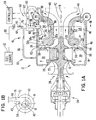
- FIG. 1A With initial reference to Fig. 1A, there is shown a combustor system made in accordance with the present invention and designated generally by the numeral 10.
- System 10 is depicted as being used in conjunction with radial gas turbine engine module 12.
- Gas turbine engine module 12 includes a pressure housing 14 within which is mounted shaft 16 rotatable about axis 18. Mounted on one end of a shaft 16 is radial turbine 20 for driving centrifugal compressor 22 mounted at the opposed end of shaft 16.
- gas turbine engine module 12 power is taken out through a mechanical coupling arrangement shown generally at 24 adjacent centrifugal compressor 22.
- the combustor system and gas turbine engine module of the present invention can be utilized in association with a "free power turbine” (not shown), or any other turbine engine version as one skilled in the art would immediately realize.
- the present invention is not limited to use with radial gas turbine engine modules but, at least in its broadest extent, could be used with axial or mixed axial-radial turbine engine modules as well.
- gas turbine engine module 12 operates generally as follows. Air enters centrifugal compressor 22 in a direction designated by the arrows 26, is centrifugally accelerated to increase its velocity, whereupon it enters diffuser 28 to increase static pressure. The compressed air exiting diffuser 28 is collected in a plenum chamber 30. Thereafter, compressed air from plenum 30 is mixed with fuel from a fuel source 32 by means of premixer 60 of combustor system 10, to be described in more detail hereinafter, to produce hot exhaust gases which flow past inlet guide vanes 34 to radial turbine 20, where power is extracted. The exhaust gases from turbine 20 are ducted to the atmosphere or to a subsequent engine module. In the case of free power turbine arrangement, the gases exiting turbine 20 would be ducted to the free power turbine for extraction of further power.
- the combustor system includes a cylindrical housing defining a combustion chamber, the housing having an axis and having at least one inlet port adjacent one axial chamber end.
- the portion of the chamber adjacent the one axial chamber end comprises a single stage combustion zone.
- An exhaust is positioned at the opposite axial chamber end, with the portion of the combustion chamber adjacent the opposite axial chamber end comprising a dilution zone.
- the housing further has aperture means in the form of dilution ports in flow communication with the dilution zone.
- combustor system 10 includes annular combustor lining housing 40 which is generally toroidal in shape. Although the preferred embodiment is illustrated with an annular housing, a “can-type" cylindrical housing could also be used. Housing 40 is contained within pressure vessel 14 and defines an axis 42 essentially coincident with gas turbine engine module axis 18. Housing 40 is closed at axial end 44 except for inlet port 43, but is open at axial end 46 to form an annular exhaust port 48. Exhaust port 48 is in flow communication with radial turbine 20 through channel 50 past inlet guide vanes 34.
- toroidal chamber 52 defined by housing 40 comprises two generally axial sections with different functions.
- Section 54 adjacent axial end 44 comprises a single stage combustion zone and section 56 adjacent housing end 46, comprises a dilution zone.
- a plurality of apertures 58a, 58b are provided in housing 40 opening into dilution zone 56.
- Dilution ports 58a are a series of apertures formed in the outer peripheral surface of housing 40, while dilution ports 58b are a series of apertures formed in an inner peripheral surface of housing 40, relative to housing axis 42.
- the aperture means generally comprising dilution ports 58a, 58b provide for the introduction of compressed air into the dilution zone 56 of combustion chamber 52 from compressed air conduit means which will be described in more detail hereinafter.
- dilution apertures need not be placed in both inner and outer walls of the combustion liner.
- aperture 58a may be eliminated if apertures 58b are used and sized to accommodate the entire dilution flow rate.
- At least one fuel/air premixer disposed outside the cylindrical housing is provided for mixing a portion of the compressed air flow with fuel to provide a fuel/air mixture and delivering the mixture to the combustion zone through the inlet port.
- the fuel/air premixer includes means for receiving the compressed air, means for receiving the fuel and also chamber means for flow-smoothing the received compressed air and for mixing the received compressed air and fuel.
- combustion system 10 further includes a single fuel/air premixer designated generally by the numeral 60.
- Premixer 60 includes housing assembly 62 for receiving the compressed air from conduit means which will be described in more detail hereinafter, and a single fuel nozzle 64 for receiving fuel from fuel source 32 via fuel line 66.
- Fuel nozzle 64 depicted in Fig. 1A is an "air-blast" type fuel nozzle especially advantageous for use with liquid fuel to provide atomization and thus enhance vaporization.
- use of an "air blast” nozzle with gaseous fuel can provide benefits in terms of providing an initial mixing of the fuel with air prior to admission to the venturi element which will be described hereinafter. Therefore, the combustion system of the present invention is not restricted to the use of liquid fuel or an "air-blast” fuel nozzle, but gaseous fuel and other types of fuel nozzles, such as swirling-type nozzles, can be used as well.
- Fuel/air premixer 60 further includes mixing chamber means in the form of venturi 68 having venturi inlet 70 disposed within fuel/air premixer housing assembly 62 and venturi exit 72 connected to inlet port 43.
- Venturi 68 defines a flow axis 74, and fuel nozzle 64 is positioned to deliver a fuel spray into venturi inlet 70 substantially along axis 74.
- the cross sectional flow area and dimensions of venturi 68 are chosen to provide vigorous and complete mixing of the fuel and compressed air within the venturi chamber and a directed flow of the resulting mixture along venturi axis 74 to combustion zone 54, such as indicated schematically by arrow 76.
- venturi exit 72 should be chosen such that minimum velocities of the mixture (i.e., during idle) are greater than the flame propagation speed of the fuel/air mixture.
- Flame holder means such as depicted schematically as 78 may be provided proximate venturi exit 72 to enhance the stability of combustion in combustion zone 54.
- mixing venturi 68 is disposed such that venturi axis 74 is oriented substantially tangentially with respect to housing axis 42 such that the incoming fuel/air mixture is caused to swirl about axis 42 within the combustion zone 54. It has been found using the preferred premixer construction to be described in more detail henceforth that combustion chamber 52 can be adequately fed by using only a single fuel/air premixer fed by a single fuel nozzle. However, the present invention contemplates the possible use of multiple fuel/air premixers, particularly for situations wherein the radial "thickness" of combustion chamber 52 is small relative to the outer radius thereof, as measured from axis 42.
- compressed air conduit means are provided interconnecting the source of compressed air and the fuel/air premixer for delivering a portion of the compressed flow to the premixer compressed air receiving means and for delivering essentially the remaining portion of the compressed air flow to the aperture means for providing dilution air to the dilution zone.
- compressed air conduit means designated generally by the numeral 80 includes generally annular passageway 82 disposed between pressure housing 14 and housing 40. Passageway 82 extends between compressed air receiving plenum 30 and a ring-shaped plenum 84 and is formed as part of pressure vessel 14 adjacent the turbine exhaust section.
- Fuel/air premixer housing assembly 62 is connected to receive compressed air from plenum 84 for eventual communication to the venturi inlet 70 as explained previously.
- Plenum 84 is shown having a circular cross section but other shapes, configurations and locations are possible and are considered within the scope of the present invention.
- passageway 82 is configured such that the compressed air flowing therein provides cooling for housing 40, particularly housing portion 86 immediately surrounding the combustion zone 54 where the highest combustion temperatures are expected.
- Portion 86 of housing 40 is constructed for convection cooling only, with no film-cooling necessary. That is, in portion 86 of housing 40, the housing acts to seal off the compressed air flowing in passageway 82 from the fuel/air mixture being combusted in combustion zone 54.
- This construction provides for better control of the fuel/air ratio of the mixture in combustion zone 54 and permits operation as a "single stage combustor" with a desired lean fuel/air ratio. Such an operation can yield low levels of NO x and unburned fuel and fuel by-product levels.
- the particular construction of the combustor system of the present invention permits extraordinarily low levels of NO x in comparison with other state of the art combustion systems.
- Passageway 82 essentially envelopes combustion chamber 52 to provide convection cooling and also to supply compressed air to dilution ports 58a and 58b. Passageway 82 also may include a channel 82a for channeling compressed air flow for cooling the portion of the pressure vessel 14 adjacent turbine 20, as is shown in Fig. 1A. Turbine inlet guide vanes 34 may be film cooled inlet guide vanes and may be fed from passageway 82 or 82a. Also, compressed air conduit means 80 can include a separate passageway 88 interconnecting the compressed air receiving plenum 30 and air-blast fuel nozzle 64 when such a nozzle is used, particularly with liquid fuel operation.
- compressed air conduit means 80 acts to channel a portion of the compressed air flow to the fuel/air premixer 60 and to channel essentially the remaining portion of the compressed air flow to the dilution ports 58a and 58b.
- the compressed air flow not channeled to either the fuel/air premixer or the dilution ports, namely the air used to cool the inlet guide vanes 34, is very small and in any event results in a small further dilution of the exhaust gases prior to entry into turbine 20.
- valve means are disposed in the compressed air flow path for determining the compressed air flow rate to the premixer.
- valve 90 is positioned in fuel/air premixer housing assembly 62 for determining the rate of compressed air flow from plenum 84 to venturi inlet 70.
- Valve 90 is continuously adjustable, and a suitable construction of valve 90 will be discussed in more detail hereinafter in relation to the description of the preferred construction of the fuel/air premixer of the present invention.
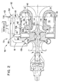
- Fig. 2 discloses combustor system 110 having an alternate configuration for the compressed air conduit means. Components having the same or similar function relative to the embodiment in Figs. 1A, 1B are given the same numeral but with a "100" base.
- a distribution conduit 181 is provided between compressed air collection plenum 130 and annular passageway 182 surrounding housing 140, and fuel/air premixer housing assembly 162 is directly connected to distribution conduit 181 upstream of passageway 182.
- Valve 190 is disposed at the connection between fuel/air premixer housing assembly 162 and distribution conduit 181 to positively divide the air flow into a first portion flowing to fuel/air premixer 160 and the remainder to passageway 182 via distribution conduit portion 181a.
- Fig. 2 embodiment does allow for the direct control of the compressed air fractions flowing to the fuel/air premixer versus the compressed air flow fraction flowing to the dilution ports 158a and 158b.
- the configuration shown in Fig. 1A may be preferred nonetheless because of an ease of construction in assembly of the various components, principally the fuel/air premixer wherein the valve can be integrated directly with the fuel/air premixer housing, as will be discussed in more detail henceforth.
- fuel conduit means is provided interconnecting the fuel supply and the premixer fuel receiving means, the fuel conduit means together with the premixer fuel receiving means establishing a flow path for all the fuel to the premixer.
- Fuel valve means is disposed in the fuel flow path for determining the fuel flow rate therein.
- fuel line 66 interconnects fuel source 32 with fuel nozzle 64.
- Fuel valve 92 is disposed in fuel line 66 immediately upstream of fuel nozzle 64, which is depicted as being an "air-blast" type fuel nozzle particularly suitable for use with liquid fuels, as stated previously.
- the combustor system includes controller means operatively connected both to the compressed air valve means and the fuel valve means for essentially controlling the respective flow rates of the compressed air portion and the fuel delivered to the premixer to provide a preselected lean fuel/air ratio mixture through the inlet port to the combustion zone.
- controller 94 which can be either mechanical or electric (e.g., a microprocessor) is interconnected with compressed air valve 90 to essentially control the flow rate of the compressed air flowing directly to venturi inlet 70.
- conduit 88 While a small portion (typically 5% or less), of the total compressed air flowing to fuel/air premixer 60 can travel through conduit 88 when an "air-blast" nozzle is utilized, the control provided by valve 90 of the remaining 95+% of the compressed air flow is expected to achieve adequate overall fuel/air ratio control. Moreover, for situations utilizing gaseous fuel, such as natural gas as provided in the Example to be discussed hereinafter, conduit 88 could be eliminated such that all of the compressed air flow to the fuel/air premixer will be under the control of the compressed air flow valve.
- gaseous fuel such as natural gas as provided in the Example to be discussed hereinafter
- controller 94 is operatively connected to fuel valve 92 to meter the fuel flow to fuel nozzle 64.
- controller 94 can act to control both the fuel flow and the compressed air flow to fuel/air premixer 60 to achieve a single preselected fuel/air ratio mixture over the entire operating range of the gas turbine engine module so that the mass flow of the combustible mixture would change as a function of the load.
- controller 94 can be configured to provide a sequence of preselected fuel/air ratio mixtures as a function of load.
- One skilled in the art would be able to select and adapt a suitable controller for a particular application based on the present disclosure and the general knowledge in the art.
- compressed air from compressed air receiving means 30 is channeled via passageway/envelope 82 over the outside surface of housing 40 for cooling housing 40, and particularly portions 86 which surround combustion zone 54.
- a portion of the compressed air flowing in passageway 82 is admitted to plenum 84 and then flows to fuel/air premixer 60 via the interconnection between fuel/air premixer housing assembly 62 and 84 as controlled by compressed air valve 90 via controller 94.
- venturi 68 the compressed air portion is mixed with the fuel from fuel nozzle 64, possibly with a small additional portion of compressed air if nozzle 64 is a "air-blast" type nozzle, and is injected along the venturi axis 74 through inlet port 43 and into combustion zone 54 of combustion chamber 52.
- venturi axis 74 As shown in Fig. 1B, swirling flow and combustion is provided in combustion zone 54 by locating venturi axis 74 tangentially with respect to axis 42 of the housing.
- the direction of orientation of the venturi axis 74 is chosen to give a specific angular direction (clockwise or counterclockwise) with respect to the direction of rotation of the turbine in order to provide some aerodynamic unloading of the inlet guide vanes.
- the direction of rotation of turbine 20 also would be in the clockwise direction.
- the hot exhaust gases pass to dilution zone 56 where dilution air from dilution ports 58a, 58b reduce the average temperature of the exhaust before it is ducted via channel 50 past inlet guide vanes 34 to turbine 20 for work-producing expansion.
- combustion system 10 in accordance with the present invention through the complete mixing of the fuel and air outside the combustion chamber in the fuel/air premixer, including complete vaporization of the fuel if liquid fuel is used, together with the control of the fuel/air ratio of the mixture delivered to the combustion chamber allows for significant reductions in NO x levels and the levels of unburned fuel and fuel by-products, as mentioned earlier. Furthermore, the utilization of essentially the total amount of compressed air flow to either combust the fuel or to dilute the exhaust gases upstream of the turbine provides considerable reduction of peak combustor temperatures resulting in longer life of combustion liners.
- the preferred fuel/air premixer of the present invention includes a compressed air receiving means, a venturi having an inlet operatively connected to the compressed air receiving means with air flow smoothing means, a fuel receiving means including a nozzle with an exit positioned to deliver a spray of fuel into the venturi inlet substantially along the venturi axis, and valve means associated with the compressed air receiving means for determining the compressed air flow rate to the venturi inlet.
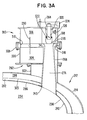
- fuel/air premixer 260 includes air receiving means in the form of housing assembly 262. Components having a like or similar function to those disclosed in the embodiments of Figs. 1A and 1B will be designated by the same numeral but with a "200" base.
- Housing assembly 262 in turn, includes housing 300 and housing support 302 for mounting housing 300 on pressure vessel 214 of gas turbine engine module 212.
- Housing support 302 is hollow and, in addition to supporting housing 300 and the components contained therein, acts to channel compressed air from plenum 284 to housing 300.
- liner member 303 is positioned between combustion chamber housing 240 and pressure vessel 214 for establishing the flow path 282, at least in the vicinity of portions 286 of housing 240 that define the boundary of the combustion zone 254. Liner member 303 also defines with pressure vessel 214, plenum 284 for collecting the compressed air portion for eventual transmission to housing 300 via housing support 302.
- fuel/air premixer housing 300 is divided into upstream and downstream compartments 304, 306 respectively by divider plate 308.
- Aperture 310 is provided in divider plate 308, and a butterfly-type valve plate 290 is mounted for rotation in aperture 310.
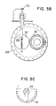
- the orientation of valve plate 290 in aperture 310 is controlled through control arm 312 (see Fig. 3B) to provide a selective degree of obstruction and, hence, pressure drop.
- a minimum amount of obstruction occurs with valve plate 290 being oriented perpendicular to the divider plate 308, corresponding to a "zero" setting of the angular calibration plate 314 shown in Fig.
- control rod 312 corresponding to either "9" position on indicator 314 would result in the greatest amount of obstruction and pressure drop in the compressed air portion flowing through aperture 310.
- the degree of obstruction and thus control of the compressed air flow between upstream compartment 304 and downstream compartment 306 could be varied by changing the angular orientation of control rod 312 between the "zero” and “9” positions, thereby controlling the compressed air flow rate to the balance of the fuel/air premixer 260 which will now be described in more detail.
- Divider plate 308 includes an additional aperture 316 in which is mounted inlet 270 of venturi 268.
- Venturi inlet 270 is configured and mounted to divider plate 308 such that a smooth transition exists between the upper planar surface of divider plate 308 and the inner surface of venturi inlet 270.
- Venturi 268 extends through upstream housing compartment 304, housing support 302, past pressure vessel 214, combustion chamber liner 303, and connects to housing 240 at the location of inlet port 243.
- the venturi axis 274 which corresponds generally to the flow direction of the fuel/air mixture in venturi 268 is oriented to provide a substantially tangential admission direction with respect to the axis (not shown) of annular combustion chamber housing 240.
- fuel nozzle 264 is mounted in downstream compartment 306 with the fuel nozzle exit 318 positioned to deliver a spray of fuel into venturi inlet 270 along venturi axis 274.
- Fuel nozzle 264 is of the "swirling" spray type which utilizes ports 320 and swirl vanes 322 to channel some of the compressed air swirl the fuel entering through fuel port 324 before releasing the fuel spray through exit 318.
- perforated flow-smoothing element 326 positioned in the downstream compartment 306 and surrounding fuel nozzle exit 318 and venturi inlet 270, to avoid uneven velocities and separation in the venturi which otherwise could result in "flame holding" in the venturi.
- the perforated element 326 has been found to provide increased stability for the compressed air flow from downstream compartment 306 past the fuel nozzle 264 and into venturi inlet 270, without any separation at the lip of venturi inlet 270.
- Fig. 4 shows a contemplated commercial variation of the preferred fuel/air premixer depicted in Figs. 3A-3C, which variation is designated generally by the numeral 360.
- Fuel/air premixer 360 includes a venturi 368 which has inlet 370 which extends slightly above the surface of divider plate 408. Also, fuel nozzle exit 418 extends a distance into venturi inlet 370.
- venturi 368 which has inlet 370 which extends slightly above the surface of divider plate 408.
- fuel nozzle exit 418 extends a distance into venturi inlet 370.
- Fig. 4 embodiment incorporates contemplated refinements in the construction of the fuel/air premixer compared to the construction shown in Fig. 3A, such as the use of integral, bell-shaped housing 400.
- annular combustor having the fuel/air premixer as shown in Figs. 3A-3C was atmospherically tested using an external source of air and a gaseous fuel (natural gas).
- Table 1 presents values of the important dimensions of the apparatus used in the test.
- Volume of combustion chamber (12.3x10 -3 m 3 )
- Outer diameter of combustion zone (0.346 m)
- Inner diameter of combustion zone (0.200 m)
- Exit 75mm
- Perforated element hole diameter and pitch ⁇ 3.75x5mm
- Tests were done at flow conditions corresponding to idle and full load. Flow rates to achieve a preselected fuel/air ratio were set by manually setting compressed air valve 290 and the fuel valve (not shown) rather than by a controller element although a controller element could have been used. Table 2 presents the fuel and compressed air flow rates and other important parameters as well as the measured NO x levels and approximate CO emission levels for the tests.
Landscapes
- Engineering & Computer Science (AREA)
- Chemical & Material Sciences (AREA)
- Combustion & Propulsion (AREA)
- Mechanical Engineering (AREA)
- General Engineering & Computer Science (AREA)
- Physics & Mathematics (AREA)
- Fluid Mechanics (AREA)
Claims (21)
- Système de chambre de combustion à un seul étage destiné à fonctionner avec une source d'air comprimé (30) et une source de carburant (32), la chambre de combustion comprenant :caractérisé en ce queune enceinte de revêtement de chambre de combustion cylindrique (40, 140, 240) définissant une chambre de combustion à un seul étage, ladite enceinte ayant un axe (42) et comportant au moins un orifice d'admission (43, 243) à proximité d'une première extrémité axiale de la chambre (44), la partie (54) de ladite chambre à proximité de ladite première extrémité axiale de la chambre comprenant une zone de combustion à un seul étage, un orifice d'échappement (50) au niveau de l'extrémité axiale opposée de la chambre, la partie (56) de ladite chambre à proximité de ladite extrémité axiale opposée de la chambre comprenant une zone de dilution, et ladite enceinte comportant également des moyens d'orifices (58a, b ; 158a, b) s'ouvrant dans ladite zone de dilution,au moins un dispositif de prémélange de carburant/air (60, 160, 260, 360) disposé à l'extérieur de ladite enceinte cylindrique, et comportant un moyen destiné à recevoir de l'air comprimé (62, 162, 262), un moyen destiné à recevoir du carburant (64, 164, 264), et un moyen de chambre de prémélange destiné à mélanger l'air comprimé et le carburant reçus et à délivrer le mélange à ladite zone de combustion par l'intermédiaire dudit orifice d'admission,un premier moyen de conduite (80, 180) reliant la source d'air comprimé et ledit dispositif de prémélange et, en association avec ledit moyen de réception d'air comprimé du dispositif de prémélange, établissant une voie d'écoulement d'air comprimé afin de délivrer une partie de l'air comprimé audit dispositif de prémélange, ledit premier moyen de conduite servant également à délivrer essentiellement la partie restante de l'air comprimé audit moyen d'orifice,un premier moyen de vanne (90, 190, 290) disposé dans ladite voie d'écoulement d'air comprimé afin de déterminer essentiellement le débit d'air comprimé vers ledit dispositif de prémélange,un second moyen de conduite (66, 166) reliant la source de carburant et ledit moyen de réception de carburant du dispositif de prémélange et, en association avec ledit moyen de réception de carburant du dispositif de prémélange, établissant une voie d'écoulement pour la totalité du carburant vers le dispositif de prémélange, etun second moyen de vanne (92) disposé dans ladite voie d'écoulement du carburant afin de déterminer le débit du carburant dans celle-ci,ledit moyen de chambre de dispositif de prémélange comprend un venturi (68, 268, 368) comportant une entrée (70, 270, 370), une sortie (72), et un axe d'écoulement (74, 274, 374), ladite entrée de venturi étant en communication avec ledit moyen de réception d'air comprimé et ledit moyen de réception de carburant, et ladite sortie étant reliée audit orifice d'admission de l'enceinte afin de délivrer le mélange de carburant/air à ladite zone de combustion, etun moyen de contrôleur (94) relié fonctionnellement auxdits premier et second moyens de vannes afin de commander essentiellement les débits respectifs de ladite partie d'air comprimé et dudit carburant vers ledit dispositif de prémélange, afin de procurer un mélange pauvre à rapport carburant/air présélectionné, depuis ledit venturi, à travers ledit orifice d'admission, à ladite zone de combustion sur pratiquement la totalité de la plage de fonctionnement du système de chambre de combustion.
- Système de chambre de combustion selon la revendication 1, dans lequel ledit premier moyen de conduite comprend au moins un passage (86, 186) destiné au refroidissement par convection de la partie de ladite enceinte cylindrique qui définit ladite zone de combustion avec au moins la partie restante de l'air comprimé, l'air comprimé qui circule dans ledit passage étant isolé de ladite zone de combustion par ladite partie d'enceinte définissant la chambre.
- Système de chambre de combustion selon la revendication 2, dans lequel ledit premier moyen de conduite permet également le refroidissement par convection de ladite partie d'enceinte définissant la chambre à l'aide de la partie de l'air comprimé qui s'écoule vers ledit moyen de réception d'air comprimé du dispositif de prémélange.
- Système de chambre de combustion selon la revendication 1, dans lequel ledit premier moyen de vanne est intégré audit moyen de réception d'air comprimé du dispositif de prémélange.
- Système de chambre de combustion selon la revendication 1, dans lequel ledit venturi est disposé avec ledit axe d'écoulement aligné suivant une direction sensiblement tangentielle par rapport audit axe de l'enceinte.
- Système de chambre de combustion selon la revendication 1, dans lequel ledit moyen de réception de carburant du dispositif de prémélange comprend au moins une buse de carburant (64, 164, 264) positionnée de façon à diriger un flux de carburant jusque dans l'entrée dudit venturi pratiquement suivant l'axe dudit venturi.
- Système de chambre de combustion selon la revendication 6, dans lequel ladite buse de carburant du dispositif de prémélange est une buse à soufflage d'air destinée à assurer un prémélange initial du carburant et de l'air, et dans lequel ledit premier moyen de conduite comprend un élément de conduite (88) reliant directement la source d'air comprimé et ladite buse de soufflage d'air.
- Système de chambre de combustion selon la revendication 7, dans lequel le carburant est du carburant liquide, et dans lequel ladite buse de soufflage d'air assure également l'atomisation du carburant liquide avant son entrée dans ladite entrée du venturi.
- Système de chambre de combustion selon la revendication 6, dans lequel ledit moyen de réception de carburant du dispositif de prémélange ne comporte que ladite une buse de carburant.
- Système de chambre de combustion selon la revendication 6, dans lequel ladite buse de carburant est espacée de ladite entrée du venturi suivant la direction axiale du venturi afin de définir une voie d'écoulement en entrée optimum pour l'air comprimé jusque dans ladite entrée du venturi, et dans lequel un élément de régulation d'écoulement (326, 426) est positionné dans ladite voie d'écoulement en entrée.
- Système de chambre de combustion selon la revendication 1, ne comportant que ledit un dispositif de prémélange de carburant/air afin de fournir le mélange de carburant/air à ladite zone de combustion.
- Système de chambre de combustion selon la revendication 1, dans lequel ledit dispositif de prémélange comprend en outre un moyen de buse de carburant comportant une buse dont la sortie est positionnée de façon à délivrer une pulvérisation de carburant dans ladite entrée du venturi pratiquement suivant ledit axe du venturi, et dans lequelledit premier moyen de vanne est intégré audit moyen de réception d'air comprimé.
- Système de chambre de combustion selon la revendication 12, dans lequel ledit moyen de réception d'air comprimé comprend :une enceinte,une plaque de séparation (38) séparant l'enceinte en un compartiment amont (304) et un compartiment aval (306) par rapport au trajet d'écoulement de l'air comprimé, ladite plaque de séparation comprenant une ouverture (310),dans lequel ledit premier moyen de vanne comprend une plaque de commande de débit (290) montée en rotation dans ladite ouverture et mobile entre une position ouverte dans laquelle l'écoulement d'air comprimé à travers ladite ouverture est pratiquement libre, ce qui correspond à des conditions de pleine ouverture des gaz, et une position fermée dans laquelle l'écoulement de l'air comprimé à travers ladite ouverture est sensiblement arrêtée, ce qui correspond à des conditions de ralenti, etdans lequel ladite partie aval de l'enceinte entoure ladite sortie (318) de la buse de carburant et ladite entrée du venturi.
- Système de chambre de combustion selon la revendication 13, dans lequel ledit moyen de réception d'air comprimé comprend en outre un élément perforé positionné dans ledit compartiment aval, et entourant ladite entrée du venturi afin de stabiliser l'écoulement d'air comprimé jusque dans ladite entrée du venturi.
- Module de moteur à turbine à gaz (12) comprenant le système de chambre de combustion de la revendication 1, et comprenant en outre un moyen de compresseur d'air (22), un moyen de turbine (20) relié de façon à entraíner ledit moyen de compresseur d'air, et une voie d'écoulement des gaz d'échappement reliant ledit orifice d'échappement et ledit moyen de turbine, dans lequel ledit premier moyen de conduite est relié fonctionnellement audit moyen de compresseur d'air, dans lequel pratiquement la totalité de la partie restante de l'air comprimé provenant dudit moyen de compresseur d'air est admise dans ladite voie d'écoulement d'échappement en amont dudit moyen de turbine, et dans lequel ledit moyen de contrôleur procure ledit rapport carburant/air pauvre présélectionné sur pratiquement la totalité de la plage de fonctionnement du module de moteur à turbine à gaz.
- Module de moteur à turbine à gaz comprenant le système de chambre de combustion de la revendication 1, et comprenant en outre une turbine, une voie d'écoulement de l'échappement destinée à canaliser les gaz de la combustion depuis ledit orifice d'échappement vers ladite turbine, et des ailettes de guidage d'entrée (34) positionnées dans ladite voie d'écoulement de l'échappement en amont de ladite turbine, dans lequel ladite direction d'alignement pratiquement tangentielle dudit axe du venturi est choisie par rapport au sens de rotation de ladite turbine afin de décharger en partie aérodynamiquement lesdites ailettes de guidage d'entrée.
- Procédé de mise en oeuvre d'un module de moteur à turbine à gaz comportant un système de combustion à un seul étage afin de minimiser les émissions de NOx et de carburant non brûlé et de sous-produits du carburant, le module de moteur étant du type comportant une enceinte cylindrique présentant un axe et définissant une chambre de combustion, l'enceinte comportant au moins un orifice d'admission à proximité d'une première extrémité axiale de l'enceinte, la partie de chambre à proximité de la première extrémité axiale de l'enceinte comprenant une zone de combustion, et un orifice d'échappement ainsi qu'un moyen d'ouverture à proximité de l'autre extrémité axiale de l'enceinte, la partie de la chambre à proximité de l'autre extrémité axiale de l'enceinte comprenant une zone de dilution, le procédé comprenant les étapes consistant à :fournir un écoulement d'air comprimé et un écoulement de carburant au voisinage de l'enceinte,prémélanger en permanence la totalité de l'écoulement de carburant avec une partie de l'écoulement d'air comprimé dans un venturi positionné à l'extérieur de l'enceinte, le venturi comportant une entrée, un axe, et une sortie, et injecter le mélange de carburant/air résultant à partir de la sortie dudit venturi jusque dans la zone de combustion par l'intermédiaire de l'orifice d'admission de l'enceinte suivant une direction permettant une combustion tourbillonnante autour de l'axe de l'enceinte,admettre le reste de l'écoulement d'air comprimé dans la zone de dilution par l'intermédiaire du moyen d'ouverture, et commander le débit du carburant et le débit de la partie de l'air comprimé afin d'obtenir un mélange présentant un rapport carburant/air pauvre essentiellement prédéterminé sur pratiquement la totalité de la plage de fonctionnement du module de moteur à turbine à gaz.
- Procédé de mise en oeuvre d'un module de moteur à turbine à gaz selon la revendication 17, comprenant l'étape consistant à refroidir par convection la partie de l'enceinte qui définit la zone de combustion à l'aide d'au moins le reste de l'écoulement d'air comprimé, tout en conservant le rapport carburant/air pauvre prédéterminé du mélange dans la zone de combustion.
- Procédé de mise en oeuvre d'un module de moteur à turbine à gaz selon la revendication 18, dans lequel une partie substantielle de la partie du débit d'air comprimé est également utilisée dans ladite étape de refroidissement par convection.
- Procédé de mise en oeuvre d'un module de moteur à turbine à gaz selon la revendication 17, dans lequel ladite étape consistant à prémélanger en continu comprend l'introduction de la totalité du débit de carburant et de la partie du débit d'air comprimé dans l'entrée du venturi et l'orientation de l'axe du venturi de façon que le débit de mélange à partir de la sortie du venturi pénètre dans la zone de combustion suivant une direction pratiquement tangentielle à l'axe de l'enceinte.
- Procédé de mise en oeuvre d'un module de moteur à turbine à gaz selon la revendication 17, dans lequel un débit de carburant liquide est assuré, et dans lequel l'étape d'introduction du carburant comprend l'étape préliminaire consistant à atomiser le carburant avant son admission dans l'entrée du venturi.
Applications Claiming Priority (2)
| Application Number | Priority Date | Filing Date | Title |
|---|---|---|---|
| US8688393A | 1993-07-07 | 1993-07-07 | |
| US86883 | 1993-07-07 |
Publications (2)
| Publication Number | Publication Date |
|---|---|
| EP0635681A1 EP0635681A1 (fr) | 1995-01-25 |
| EP0635681B1 true EP0635681B1 (fr) | 1998-08-05 |
Family
ID=22201519
Family Applications (1)
| Application Number | Title | Priority Date | Filing Date |
|---|---|---|---|
| EP94109802A Expired - Lifetime EP0635681B1 (fr) | 1993-07-07 | 1994-06-24 | Chambre de combustion à prémélange d'un rapport constant carburant/comburant et avec combustion dans une seule étappe |
Country Status (4)
| Country | Link |
|---|---|
| US (3) | US5377483A (fr) |
| EP (1) | EP0635681B1 (fr) |
| JP (1) | JP3527779B2 (fr) |
| DE (1) | DE69412191T2 (fr) |
Cited By (1)
| Publication number | Priority date | Publication date | Assignee | Title |
|---|---|---|---|---|
| US6925809B2 (en) | 1999-02-26 | 2005-08-09 | R. Jan Mowill | Gas turbine engine fuel/air premixers with variable geometry exit and method for controlling exit velocities |
Families Citing this family (51)
| Publication number | Priority date | Publication date | Assignee | Title |
|---|---|---|---|---|
| US5613357A (en) * | 1993-07-07 | 1997-03-25 | Mowill; R. Jan | Star-shaped single stage low emission combustor system |
| US6220034B1 (en) | 1993-07-07 | 2001-04-24 | R. Jan Mowill | Convectively cooled, single stage, fully premixed controllable fuel/air combustor |
| US5638674A (en) * | 1993-07-07 | 1997-06-17 | Mowill; R. Jan | Convectively cooled, single stage, fully premixed controllable fuel/air combustor with tangential admission |
| US5572862A (en) * | 1993-07-07 | 1996-11-12 | Mowill Rolf Jan | Convectively cooled, single stage, fully premixed fuel/air combustor for gas turbine engine modules |
| EP0731316A1 (fr) * | 1995-02-24 | 1996-09-11 | R. Jan Mowill | Système de combustion en forme d'étoile, monoétage, à faibles émissions polluantes |
| US5669218A (en) * | 1995-05-31 | 1997-09-23 | Dresser-Rand Company | Premix fuel nozzle |
| US5558069A (en) * | 1995-11-09 | 1996-09-24 | Livernois Research & Development Company | Method and apparatus for fluid temperature control |
| US5924276A (en) * | 1996-07-17 | 1999-07-20 | Mowill; R. Jan | Premixer with dilution air bypass valve assembly |
| US6250066B1 (en) | 1996-11-26 | 2001-06-26 | Honeywell International Inc. | Combustor with dilution bypass system and venturi jet deflector |
| US6070406A (en) * | 1996-11-26 | 2000-06-06 | Alliedsignal, Inc. | Combustor dilution bypass system |
| US6233915B1 (en) * | 1997-04-17 | 2001-05-22 | Allied Signal, Inc. | Injection tube for connecting a cold plenum to a hot chamber |
| WO1999006771A1 (fr) | 1997-07-31 | 1999-02-11 | Alliedsignal Inc. | Elements generateurs de turbulence de type nervure pour refroidissement exterieur d'une chambre de combustion |
| US5971026A (en) * | 1997-12-09 | 1999-10-26 | Honeywell Inc. | Internal geometry shape design for venturi tube-like gas-air mixing valve |
| KR100550689B1 (ko) | 1998-02-10 | 2006-02-08 | 제너럴 일렉트릭 캄파니 | 가스 터빈의 연소 시스템용 버너 및 연료와 공기의 예비혼합 방법 |
| US6253538B1 (en) | 1999-09-27 | 2001-07-03 | Pratt & Whitney Canada Corp. | Variable premix-lean burn combustor |
| WO2001040713A1 (fr) | 1999-12-03 | 2001-06-07 | Mowill Rolf Jan | Buse d'evacuation a premelangeur refroidie pour bruleur de turbine a gaz, et son procede de fonctionnement |
| US6327860B1 (en) | 2000-06-21 | 2001-12-11 | Honeywell International, Inc. | Fuel injector for low emissions premixing gas turbine combustor |
| US6363724B1 (en) | 2000-08-31 | 2002-04-02 | General Electric Company | Gas only nozzle fuel tip |
| US6543231B2 (en) * | 2001-07-13 | 2003-04-08 | Pratt & Whitney Canada Corp | Cyclone combustor |
| JP2003194338A (ja) | 2001-12-14 | 2003-07-09 | R Jan Mowill | 可変出口形状を有するガスタービンエンジン用燃料/空気プレミキサ及び出口速度の制御方法 |
| HUE059355T2 (hu) * | 2002-10-10 | 2022-11-28 | Lpp Comb Llc | Eljárás folyékony tüzelõanyagok elpárologtatására égetés céljára |
| US6971227B2 (en) * | 2003-04-16 | 2005-12-06 | Ingersoll Rand Energy Systems, Inc. | System and method to stage primary zone airflow |
| JP4317214B2 (ja) * | 2004-03-09 | 2009-08-19 | 株式会社日立製作所 | ラジアルタービン及びそのノズルの冷却方法 |
| US7162874B2 (en) * | 2004-07-30 | 2007-01-16 | Hija Holding B.V. | Apparatus and method for gas turbine engine fuel/air premixer exit velocity control |
| JP4920597B2 (ja) | 2004-12-08 | 2012-04-18 | エル・ピー・ピー コンバスション エル・エル・シー | 液体炭化水素燃料を調整する方法および装置 |
| US7540154B2 (en) * | 2005-08-11 | 2009-06-02 | Mitsubishi Heavy Industries, Ltd. | Gas turbine combustor |
| US20070107437A1 (en) * | 2005-11-15 | 2007-05-17 | Evulet Andrei T | Low emission combustion and method of operation |
| US20070151988A1 (en) * | 2005-12-14 | 2007-07-05 | Saucedo Victor M | Constant pressure delivery vessel and system |
| US8529646B2 (en) * | 2006-05-01 | 2013-09-10 | Lpp Combustion Llc | Integrated system and method for production and vaporization of liquid hydrocarbon fuels for combustion |
| US8171716B2 (en) * | 2007-08-28 | 2012-05-08 | General Electric Company | System and method for fuel and air mixing in a gas turbine |
| EP2110602A1 (fr) * | 2008-04-16 | 2009-10-21 | Siemens Aktiengesellschaft | Découplage partiel acoustique destiné à réduire des oscillations de flammes à auto-induction |
| US8887390B2 (en) | 2008-08-15 | 2014-11-18 | Dresser-Rand Company | Method for correcting downstream deflection in gas turbine nozzles |
| US7712314B1 (en) | 2009-01-21 | 2010-05-11 | Gas Turbine Efficiency Sweden Ab | Venturi cooling system |
| EP2299178B1 (fr) * | 2009-09-17 | 2015-11-04 | Alstom Technology Ltd | Procédé et système de combustion de turbine à gaz pour mélanger sans danger des carburants riches en H2 avec de l'air |
| US8863525B2 (en) | 2011-01-03 | 2014-10-21 | General Electric Company | Combustor with fuel staggering for flame holding mitigation |
| US9217370B2 (en) * | 2011-02-18 | 2015-12-22 | Dynamo Micropower Corporation | Fluid flow devices with vertically simple geometry and methods of making the same |
| US8365534B2 (en) | 2011-03-15 | 2013-02-05 | General Electric Company | Gas turbine combustor having a fuel nozzle for flame anchoring |
| RU2011115528A (ru) | 2011-04-21 | 2012-10-27 | Дженерал Электрик Компани (US) | Топливная форсунка, камера сгорания и способ работы камеры сгорания |
| US8601820B2 (en) | 2011-06-06 | 2013-12-10 | General Electric Company | Integrated late lean injection on a combustion liner and late lean injection sleeve assembly |
| US8919137B2 (en) | 2011-08-05 | 2014-12-30 | General Electric Company | Assemblies and apparatus related to integrating late lean injection into combustion turbine engines |
| US9010120B2 (en) | 2011-08-05 | 2015-04-21 | General Electric Company | Assemblies and apparatus related to integrating late lean injection into combustion turbine engines |
| US11015808B2 (en) | 2011-12-13 | 2021-05-25 | General Electric Company | Aerodynamically enhanced premixer with purge slots for reduced emissions |
| US9140455B2 (en) | 2012-01-04 | 2015-09-22 | General Electric Company | Flowsleeve of a turbomachine component |
| KR101400602B1 (ko) * | 2012-04-27 | 2014-05-27 | 부경대학교 산학협력단 | 상온공기 연소기에서 고온공기를 연속으로 공급받는 마일드 연소기 |
| US20140000269A1 (en) * | 2012-06-29 | 2014-01-02 | General Electric Company | Combustion nozzle and an associated method thereof |
| JP6327826B2 (ja) * | 2013-10-11 | 2018-05-23 | 川崎重工業株式会社 | ガスタービンの燃料噴射装置 |
| FI127525B (en) * | 2014-01-08 | 2018-08-15 | Finno Energy Oy | System and method for generating electrical energy |
| US10030580B2 (en) | 2014-04-11 | 2018-07-24 | Dynamo Micropower Corporation | Micro gas turbine systems and uses thereof |
| US20150338101A1 (en) * | 2014-05-21 | 2015-11-26 | General Electric Company | Turbomachine combustor including a combustor sleeve baffle |
| GB201414661D0 (en) * | 2014-08-19 | 2014-10-01 | Rolls Royce Plc | Gas turbine engine and method of operation |
| RU2656177C1 (ru) * | 2014-11-03 | 2018-05-31 | Сименс Акциенгезелльшафт | Компоновка горелки |
Family Cites Families (85)
| Publication number | Priority date | Publication date | Assignee | Title |
|---|---|---|---|---|
| US2675673A (en) * | 1954-04-20 | Gas turbine power plant | ||
| US1705383A (en) * | 1924-04-17 | 1929-03-12 | Mines De Frankenholz Soc D | Combustion chamber for use with powdered fuel |
| US2108822A (en) * | 1935-11-11 | 1938-02-22 | Wells A Lippincott | Printing plate and formation thereof |
| US2183836A (en) * | 1936-12-18 | 1939-12-19 | Roberts Appliance Corp Gordon | Fluid fuel burner |
| DE748208C (de) * | 1938-06-15 | 1944-10-28 | Sulzer Ag | Gasturbinenanlage |
| US2268270A (en) * | 1938-12-13 | 1941-12-30 | Sulzer Ag | Gas turbine plant |
| DE872698C (de) * | 1942-05-31 | 1953-04-02 | Kloeckner Humboldt Deutz Ag | Gasturbine bzw. Strahltriebwerk |
| US2487514A (en) * | 1943-01-16 | 1949-11-08 | Jarvis C Marble | Turbine rotor cooling |
| DE833739C (de) * | 1943-09-04 | 1952-03-10 | Maschf Augsburg Nuernberg Ag | Gasturbinenanlage |
| US2608822A (en) * | 1944-10-07 | 1952-09-02 | Turbolectric Corp | Method of operation and regulation of thermal power plants |
| US2488969A (en) * | 1945-02-27 | 1949-11-22 | Bbc Brown Boveri & Cie | Combined gas producer and gas turbine plant |
| US2489939A (en) * | 1945-05-05 | 1949-11-29 | Sulzer Ag | Variable load gas turbine system |
| US2513601A (en) * | 1945-12-29 | 1950-07-04 | Sulzer Ag | Gas turbine plant |
| US2621475A (en) * | 1946-06-13 | 1952-12-16 | Phillips Petroleum Co | Operation of multistage combustion gas turbines |
| US2469238A (en) * | 1947-08-28 | 1949-05-03 | Westinghouse Electric Corp | Gas turbine apparatus |
| GB668834A (en) * | 1948-11-02 | 1952-03-26 | Power Jets Res & Dev Ltd | Improvements in or relating to gas turbine power plant |
| CH283198A (de) * | 1949-03-25 | 1952-05-31 | Limited Centrax Power Units | Gasturbinenanlage. |
| US2625012A (en) * | 1950-04-18 | 1953-01-13 | Gen Engineering And Res Corp | Gas turbine power plant, including multiple fluid operated turbines |
| CH301137A (de) * | 1950-11-17 | 1954-08-31 | Power Jets Res & Dev Ltd | Verbrennungseinrichtung. |
| FR1126906A (fr) * | 1951-08-08 | 1956-12-04 | Turbine à gaz, plus spécialement pour véhicules | |
| US2663141A (en) * | 1952-05-03 | 1953-12-22 | Boeing Co | Gas turbine |
| CH324502A (de) * | 1954-12-18 | 1957-09-30 | Bbc Brown Boveri & Cie | Selbsttätige Luftregelungseinrichtung bei Brennkammern von Gasturbinenanlagen |
| US2999359A (en) * | 1956-04-25 | 1961-09-12 | Rolls Royce | Combustion equipment of gas-turbine engines |
| US2988884A (en) * | 1958-09-23 | 1961-06-20 | Pouit Robert | Improvements in gas turbine power plants |
| US3091080A (en) * | 1958-10-27 | 1963-05-28 | United Aircraft Corp | Control system for afterburning gas turbine engine |
| CH363853A (de) * | 1959-01-10 | 1962-08-15 | Sulzer Ag | Gasturbinenanlage mit zwei Wellen |
| US3099134A (en) * | 1959-12-24 | 1963-07-30 | Havilland Engine Co Ltd | Combustion chambers |
| US3204406A (en) * | 1960-04-04 | 1965-09-07 | Ford Motor Co | Cooling system for a re-expansion gas turbine engine |
| US3315467A (en) * | 1965-03-11 | 1967-04-25 | Westinghouse Electric Corp | Reheat gas turbine power plant with air admission to the primary combustion zone of the reheat combustion chamber structure |
| FR1590542A (fr) * | 1968-11-04 | 1970-04-13 | ||
| US3899884A (en) * | 1970-12-02 | 1975-08-19 | Gen Electric | Combustor systems |
| JPS4923482B1 (fr) * | 1970-12-27 | 1974-06-17 | ||
| FR2189630B1 (fr) * | 1972-06-23 | 1980-03-14 | Snecma | |
| US3768962A (en) * | 1972-10-02 | 1973-10-30 | F Baranowski | Gas torch |
| US3905192A (en) * | 1974-08-29 | 1975-09-16 | United Aircraft Corp | Combustor having staged premixing tubes |
| US3958413A (en) * | 1974-09-03 | 1976-05-25 | General Motors Corporation | Combustion method and apparatus |
| US3938324A (en) * | 1974-12-12 | 1976-02-17 | General Motors Corporation | Premix combustor with flow constricting baffle between combustion and dilution zones |
| US4012904A (en) * | 1975-07-17 | 1977-03-22 | Chrysler Corporation | Gas turbine burner |
| US4030288A (en) * | 1975-11-10 | 1977-06-21 | Caterpillar Tractor Co. | Modular gas turbine engine assembly |
| US4073137A (en) * | 1976-06-02 | 1978-02-14 | United Technologies Corporation | Convectively cooled flameholder for premixed burner |
| DE2629761A1 (de) * | 1976-07-02 | 1978-01-05 | Volkswagenwerk Ag | Brennkammer fuer gasturbinen |
| SE404948B (sv) * | 1977-03-25 | 1978-11-06 | Stal Laval Turbin Ab | Tvaaxlig gasturbinanleggning |
| US4215535A (en) * | 1978-01-19 | 1980-08-05 | United Technologies Corporation | Method and apparatus for reducing nitrous oxide emissions from combustors |
| US4301657A (en) * | 1978-05-04 | 1981-11-24 | Caterpillar Tractor Co. | Gas turbine combustion chamber |
| US4255927A (en) * | 1978-06-29 | 1981-03-17 | General Electric Company | Combustion control system |
| JPS5545739A (en) * | 1978-09-29 | 1980-03-31 | Japan Crown Cork Co Ltd | Bonding of polyolefin liner to metallic crown cap |
| GB2036296B (en) * | 1978-11-20 | 1982-12-01 | Rolls Royce | Gas turbine |
| US4260367A (en) * | 1978-12-11 | 1981-04-07 | United Technologies Corporation | Fuel nozzle for burner construction |
| US4286430A (en) * | 1979-09-17 | 1981-09-01 | Teledyne Industries, Inc. | Gas turbine engine |
| US4297842A (en) * | 1980-01-21 | 1981-11-03 | General Electric Company | NOx suppressant stationary gas turbine combustor |
| JPS5741524A (en) * | 1980-08-25 | 1982-03-08 | Hitachi Ltd | Combustion method of gas turbine and combustor for gas turbine |
| US4412414A (en) * | 1980-09-22 | 1983-11-01 | General Motors Corporation | Heavy fuel combustor |
| US4356698A (en) * | 1980-10-02 | 1982-11-02 | United Technologies Corporation | Staged combustor having aerodynamically separated combustion zones |
| GB2161914B (en) * | 1980-12-10 | 1986-06-11 | Rolls Royce | Combustion equipment for a gas turbine engine |
| US4389848A (en) * | 1981-01-12 | 1983-06-28 | United Technologies Corporation | Burner construction for gas turbines |
| DE3113416A1 (de) * | 1981-04-03 | 1982-10-21 | Ruhrgas Ag, 4300 Essen | Verfahren zum betrieb eines einem luftstrom ausgesetzten gasbrenners sowie brenner zur durchfuehrung des verfahrens |
| US4404806A (en) * | 1981-09-04 | 1983-09-20 | General Motors Corporation | Gas turbine prechamber and fuel manifold structure |
| DE3332959A1 (de) * | 1983-02-16 | 1985-03-28 | Horst 6208 Bad Schwalbach Dens | Einrichtung zur steuerung der verbrennung in sekundaergasstrahlverdichteranlagen fuer gasturbinen |
| US4807433A (en) * | 1983-05-05 | 1989-02-28 | General Electric Company | Turbine cooling air modulation |
| EP0169431B1 (fr) * | 1984-07-10 | 1990-04-11 | Hitachi, Ltd. | Chambre de combustion pour turbine à gaz |
| US4700542A (en) * | 1984-09-21 | 1987-10-20 | Wang Lin Shu | Internal combustion engines and methods of operation |
| US4641495A (en) * | 1985-02-05 | 1987-02-10 | A/S Kongsberg Vapenfabrikk | Dual entry radial turbine gas generator |
| GB2172053B (en) * | 1985-03-05 | 1988-10-05 | Rolls Royce | Gas turbine engine valve control system |
| US4747262A (en) * | 1985-10-04 | 1988-05-31 | Allied-Signal, Inc. | Compressor power unit fuel flow control |
| JPH0663646B2 (ja) * | 1985-10-11 | 1994-08-22 | 株式会社日立製作所 | ガスタ−ビン用燃焼器 |
| US4994149A (en) | 1986-03-06 | 1991-02-19 | Delta Projects Inc. | Diluent substitution apparatus |
| SE453114B (sv) * | 1986-04-29 | 1988-01-11 | Asea Stal Ab | Sett for drift av ett turbinaggregat |
| US4838029A (en) * | 1986-09-10 | 1989-06-13 | The United States Of America As Represented By The Secretary Of The Air Force | Externally vaporizing system for turbine combustor |
| JP2644745B2 (ja) * | 1987-03-06 | 1997-08-25 | 株式会社日立製作所 | ガスタービン用燃焼器 |
| US4845944A (en) * | 1987-05-18 | 1989-07-11 | Sundstrand Corporation | Dual mode gas turbine power plant |
| EP0312620B1 (fr) * | 1987-10-19 | 1991-06-12 | Hitachi, Ltd. | Dispositif de réglage du débit de l'air pour chambres de combustion de turbines à gaz |
| US4966001A (en) * | 1987-10-23 | 1990-10-30 | General Electric Company | Multiple venturi tube gas fuel injector for catalytic combustor |
| US4845952A (en) * | 1987-10-23 | 1989-07-11 | General Electric Company | Multiple venturi tube gas fuel injector for catalytic combustor |
| US4974415A (en) * | 1987-11-20 | 1990-12-04 | Sundstrand Corporation | Staged, coaxial multiple point fuel injection in a hot gas generator |
| US4928481A (en) * | 1988-07-13 | 1990-05-29 | Prutech Ii | Staged low NOx premix gas turbine combustor |
| DE68923413T2 (de) * | 1988-09-07 | 1996-04-04 | Hitachi Ltd | Kraftstoff-Luftvormischvorrichtung für eine Gasturbine. |
| DE3838415A1 (de) * | 1988-11-09 | 1990-05-10 | Fabeg Gmbh | Vorrichtung zum verriegeln von schienenspitzen oder weichenzungen mit zugehoerigen backenschienen |
| US4944149A (en) * | 1988-12-14 | 1990-07-31 | General Electric Company | Combustor liner with air staging for NOx control |
| US5214911A (en) * | 1989-12-21 | 1993-06-01 | Sundstrand Corporation | Method and apparatus for high altitude starting of gas turbine engine |
| US5081832A (en) * | 1990-03-05 | 1992-01-21 | Rolf Jan Mowill | High efficiency, twin spool, radial-high pressure, gas turbine engine |
| US5070700A (en) * | 1990-03-05 | 1991-12-10 | Rolf Jan Mowill | Low emissions gas turbine combustor |
| US5156002A (en) * | 1990-03-05 | 1992-10-20 | Rolf J. Mowill | Low emissions gas turbine combustor |
| US5257499A (en) * | 1991-09-23 | 1993-11-02 | General Electric Company | Air staged premixed dry low NOx combustor with venturi modulated flow split |
| US5218824A (en) * | 1992-06-25 | 1993-06-15 | Solar Turbines Incorporated | Low emission combustion nozzle for use with a gas turbine engine |
| DE9215856U1 (de) * | 1992-11-21 | 1993-01-07 | MAN Gutehoffnungshütte AG, 4200 Oberhausen | Verdichterluft-Regelung eines Vormischbrenners bei Gasturbinen-Brennkammern |
-
1994
- 1994-01-07 US US08/178,848 patent/US5377483A/en not_active Expired - Fee Related
- 1994-06-03 US US08/253,567 patent/US5477671A/en not_active Expired - Fee Related
- 1994-06-14 US US08/261,256 patent/US5481866A/en not_active Expired - Fee Related
- 1994-06-24 EP EP94109802A patent/EP0635681B1/fr not_active Expired - Lifetime
- 1994-06-24 DE DE69412191T patent/DE69412191T2/de not_active Expired - Fee Related
- 1994-06-30 JP JP17342094A patent/JP3527779B2/ja not_active Expired - Fee Related
Cited By (1)
| Publication number | Priority date | Publication date | Assignee | Title |
|---|---|---|---|---|
| US6925809B2 (en) | 1999-02-26 | 2005-08-09 | R. Jan Mowill | Gas turbine engine fuel/air premixers with variable geometry exit and method for controlling exit velocities |
Also Published As
| Publication number | Publication date |
|---|---|
| JP3527779B2 (ja) | 2004-05-17 |
| US5377483A (en) | 1995-01-03 |
| US5477671A (en) | 1995-12-26 |
| US5481866A (en) | 1996-01-09 |
| EP0635681A1 (fr) | 1995-01-25 |
| JPH07180838A (ja) | 1995-07-18 |
| DE69412191T2 (de) | 1999-01-21 |
| DE69412191D1 (de) | 1998-09-10 |
Similar Documents
| Publication | Publication Date | Title |
|---|---|---|
| EP0635681B1 (fr) | Chambre de combustion à prémélange d'un rapport constant carburant/comburant et avec combustion dans une seule étappe | |
| US5765363A (en) | Convectively cooled, single stage, fully premixed controllable fuel/air combustor with tangential admission | |
| EP0691512B1 (fr) | Chambre de combustion annulaire à prémélange pour turbines à gaz | |
| US5628182A (en) | Star combustor with dilution ports in can portions | |
| US6220034B1 (en) | Convectively cooled, single stage, fully premixed controllable fuel/air combustor | |
| US5156002A (en) | Low emissions gas turbine combustor | |
| US6925809B2 (en) | Gas turbine engine fuel/air premixers with variable geometry exit and method for controlling exit velocities | |
| CA2451318C (fr) | Methode et dispositif de reduction des emissions d'une chambre de combustion de turbine a gaz | |
| US5349812A (en) | Gas turbine combustor and gas turbine generating apparatus | |
| CA2143232C (fr) | Injecteur pour turbine capable de diffusion et de combustion d'un pre-melange; mode d'emploi | |
| US6826913B2 (en) | Airflow modulation technique for low emissions combustors | |
| EP1499800B1 (fr) | Module de premelange de combustible pour chambre de combustion de turbine a gaz | |
| US5289685A (en) | Fuel supply system for a gas turbine engine | |
| US5613357A (en) | Star-shaped single stage low emission combustor system | |
| CA2161810A1 (fr) | Chambre de combustion d'une turbine a gaz | |
| EP0731316A1 (fr) | Système de combustion en forme d'étoile, monoétage, à faibles émissions polluantes | |
| EP0773410B1 (fr) | Tube de mélange carburant/comburant | |
| US6327860B1 (en) | Fuel injector for low emissions premixing gas turbine combustor | |
| EP1036988A2 (fr) | Dispositif de prémélange carburant / air avec géométrie variable et méthode de contrôle de vitesse de sortie | |
| US20020157401A1 (en) | Diffuser combustor | |
| JPH11201454A (ja) | 空燃比が制御可能な改良された対流冷却・ 単段階・ 完全予備混合式燃焼器 | |
| WO2001040713A1 (fr) | Buse d'evacuation a premelangeur refroidie pour bruleur de turbine a gaz, et son procede de fonctionnement | |
| GB2028488A (en) | Gas Turbine | |
| WO2026048395A1 (fr) | Injecteur de carburant, chambre de combustion, turbine à gaz et système de chambre de combustion |
Legal Events
| Date | Code | Title | Description |
|---|---|---|---|
| PUAI | Public reference made under article 153(3) epc to a published international application that has entered the european phase |
Free format text: ORIGINAL CODE: 0009012 |
|
| AK | Designated contracting states |
Kind code of ref document: A1 Designated state(s): DE FR GB IT NL |
|
| 17P | Request for examination filed |
Effective date: 19950428 |
|
| 17Q | First examination report despatched |
Effective date: 19960715 |
|
| GRAG | Despatch of communication of intention to grant |
Free format text: ORIGINAL CODE: EPIDOS AGRA |
|
| GRAG | Despatch of communication of intention to grant |
Free format text: ORIGINAL CODE: EPIDOS AGRA |
|
| GRAH | Despatch of communication of intention to grant a patent |
Free format text: ORIGINAL CODE: EPIDOS IGRA |
|
| GRAH | Despatch of communication of intention to grant a patent |
Free format text: ORIGINAL CODE: EPIDOS IGRA |
|
| GRAA | (expected) grant |
Free format text: ORIGINAL CODE: 0009210 |
|
| AK | Designated contracting states |
Kind code of ref document: B1 Designated state(s): DE FR GB IT NL |
|
| PG25 | Lapsed in a contracting state [announced via postgrant information from national office to epo] |
Ref country code: NL Free format text: LAPSE BECAUSE OF FAILURE TO SUBMIT A TRANSLATION OF THE DESCRIPTION OR TO PAY THE FEE WITHIN THE PRESCRIBED TIME-LIMIT Effective date: 19980805 |
|
| REF | Corresponds to: |
Ref document number: 69412191 Country of ref document: DE Date of ref document: 19980910 |
|
| ET | Fr: translation filed | ||
| NLV1 | Nl: lapsed or annulled due to failure to fulfill the requirements of art. 29p and 29m of the patents act | ||
| PLBE | No opposition filed within time limit |
Free format text: ORIGINAL CODE: 0009261 |
|
| STAA | Information on the status of an ep patent application or granted ep patent |
Free format text: STATUS: NO OPPOSITION FILED WITHIN TIME LIMIT |
|
| 26N | No opposition filed | ||
| REG | Reference to a national code |
Ref country code: GB Ref legal event code: IF02 |
|
| PGFP | Annual fee paid to national office [announced via postgrant information from national office to epo] |
Ref country code: GB Payment date: 20050615 Year of fee payment: 12 |
|
| PGFP | Annual fee paid to national office [announced via postgrant information from national office to epo] |
Ref country code: FR Payment date: 20050617 Year of fee payment: 12 |
|
| PGFP | Annual fee paid to national office [announced via postgrant information from national office to epo] |
Ref country code: DE Payment date: 20050801 Year of fee payment: 12 |
|
| PG25 | Lapsed in a contracting state [announced via postgrant information from national office to epo] |
Ref country code: GB Free format text: LAPSE BECAUSE OF NON-PAYMENT OF DUE FEES Effective date: 20060624 |
|
| PGFP | Annual fee paid to national office [announced via postgrant information from national office to epo] |
Ref country code: IT Payment date: 20060630 Year of fee payment: 13 |
|
| PG25 | Lapsed in a contracting state [announced via postgrant information from national office to epo] |
Ref country code: DE Free format text: LAPSE BECAUSE OF NON-PAYMENT OF DUE FEES Effective date: 20070103 |
|
| GBPC | Gb: european patent ceased through non-payment of renewal fee |
Effective date: 20060624 |
|
| REG | Reference to a national code |
Ref country code: FR Ref legal event code: ST Effective date: 20070228 |
|
| PG25 | Lapsed in a contracting state [announced via postgrant information from national office to epo] |
Ref country code: FR Free format text: LAPSE BECAUSE OF NON-PAYMENT OF DUE FEES Effective date: 20060630 |
|
| PG25 | Lapsed in a contracting state [announced via postgrant information from national office to epo] |
Ref country code: IT Free format text: LAPSE BECAUSE OF NON-PAYMENT OF DUE FEES Effective date: 20070624 |