EP0635731A2 - Méthode et capteur pour déterminer la limite de visibilité dans le brouillard épais - Google Patents
Méthode et capteur pour déterminer la limite de visibilité dans le brouillard épais Download PDFInfo
- Publication number
- EP0635731A2 EP0635731A2 EP94109743A EP94109743A EP0635731A2 EP 0635731 A2 EP0635731 A2 EP 0635731A2 EP 94109743 A EP94109743 A EP 94109743A EP 94109743 A EP94109743 A EP 94109743A EP 0635731 A2 EP0635731 A2 EP 0635731A2
- Authority
- EP
- European Patent Office
- Prior art keywords
- channel
- light
- received
- reception
- lidar
- Prior art date
- Legal status (The legal status is an assumption and is not a legal conclusion. Google has not performed a legal analysis and makes no representation as to the accuracy of the status listed.)
- Granted
Links
Images



Classifications
-
- G—PHYSICS
- G01—MEASURING; TESTING
- G01N—INVESTIGATING OR ANALYSING MATERIALS BY DETERMINING THEIR CHEMICAL OR PHYSICAL PROPERTIES
- G01N21/00—Investigating or analysing materials by the use of optical means, i.e. using sub-millimetre waves, infrared, visible or ultraviolet light
- G01N21/17—Systems in which incident light is modified in accordance with the properties of the material investigated
- G01N21/47—Scattering, i.e. diffuse reflection
- G01N21/49—Scattering, i.e. diffuse reflection within a body or fluid
- G01N21/53—Scattering, i.e. diffuse reflection within a body or fluid within a flowing fluid, e.g. smoke
- G01N21/538—Scattering, i.e. diffuse reflection within a body or fluid within a flowing fluid, e.g. smoke for determining atmospheric attenuation and visibility
-
- G—PHYSICS
- G01—MEASURING; TESTING
- G01S—RADIO DIRECTION-FINDING; RADIO NAVIGATION; DETERMINING DISTANCE OR VELOCITY BY USE OF RADIO WAVES; LOCATING OR PRESENCE-DETECTING BY USE OF THE REFLECTION OR RERADIATION OF RADIO WAVES; ANALOGOUS ARRANGEMENTS USING OTHER WAVES
- G01S17/00—Systems using the reflection or reradiation of electromagnetic waves other than radio waves, e.g. lidar systems
- G01S17/88—Lidar systems specially adapted for specific applications
- G01S17/93—Lidar systems specially adapted for specific applications for anti-collision purposes
- G01S17/931—Lidar systems specially adapted for specific applications for anti-collision purposes of land vehicles
-
- G—PHYSICS
- G01—MEASURING; TESTING
- G01S—RADIO DIRECTION-FINDING; RADIO NAVIGATION; DETERMINING DISTANCE OR VELOCITY BY USE OF RADIO WAVES; LOCATING OR PRESENCE-DETECTING BY USE OF THE REFLECTION OR RERADIATION OF RADIO WAVES; ANALOGOUS ARRANGEMENTS USING OTHER WAVES
- G01S17/00—Systems using the reflection or reradiation of electromagnetic waves other than radio waves, e.g. lidar systems
- G01S17/88—Lidar systems specially adapted for specific applications
- G01S17/95—Lidar systems specially adapted for specific applications for meteorological use
-
- G—PHYSICS
- G01—MEASURING; TESTING
- G01S—RADIO DIRECTION-FINDING; RADIO NAVIGATION; DETERMINING DISTANCE OR VELOCITY BY USE OF RADIO WAVES; LOCATING OR PRESENCE-DETECTING BY USE OF THE REFLECTION OR RERADIATION OF RADIO WAVES; ANALOGOUS ARRANGEMENTS USING OTHER WAVES
- G01S7/00—Details of systems according to groups G01S13/00, G01S15/00, G01S17/00
- G01S7/48—Details of systems according to groups G01S13/00, G01S15/00, G01S17/00 of systems according to group G01S17/00
- G01S7/4802—Details of systems according to groups G01S13/00, G01S15/00, G01S17/00 of systems according to group G01S17/00 using analysis of echo signal for target characterisation; Target signature; Target cross-section
-
- Y—GENERAL TAGGING OF NEW TECHNOLOGICAL DEVELOPMENTS; GENERAL TAGGING OF CROSS-SECTIONAL TECHNOLOGIES SPANNING OVER SEVERAL SECTIONS OF THE IPC; TECHNICAL SUBJECTS COVERED BY FORMER USPC CROSS-REFERENCE ART COLLECTIONS [XRACs] AND DIGESTS
- Y02—TECHNOLOGIES OR APPLICATIONS FOR MITIGATION OR ADAPTATION AGAINST CLIMATE CHANGE
- Y02A—TECHNOLOGIES FOR ADAPTATION TO CLIMATE CHANGE
- Y02A90/00—Technologies having an indirect contribution to adaptation to climate change
- Y02A90/10—Information and communication technologies [ICT] supporting adaptation to climate change, e.g. for weather forecasting or climate simulation
Definitions
- the invention relates to a method for determining the visibility in dense fog using a lidar, from which a pulsed laser beam is transmitted through a first transmission channel and laser light backscattered from the fog is received through a first reception channel, the first transmission channel and the first reception channel being parallel to one another are aligned.
- the invention relates to a visual range sensor, in particular for performing the above method, which is provided with a lidar with a first transmitter transmitting through a first transmission channel, which transmits a pulsed laser beam, and a first receiver, which transmits light backscattered through a first reception channel receives, wherein the first transmission channel and the first reception channel are aligned parallel to each other.
- the invention relates to a visual range sensor, in particular for performing the above method, which is provided with a lidar with a single transmitter transmitting through a transmission channel, which transmits a pulsed laser beam, and a receiver, which receives light backscattered through a first reception channel , wherein the transmission channel and the first reception channel are aligned parallel to each other.
- lidar signals for measuring distances from bodies has been known for a long time.
- a pulsed laser beam is emitted and received again, the transmit channel and receive channel conventionally running parallel to one another.
- the distance of an object ie a so-called opaque hard target, from the sensor can be measured.
- This is used, for example, in testing as a vehicle security system, for security reasons For example, slight interventions in the brake or the fuel supply can take place in the event of an approaching obstacle.
- security systems make it necessary for the system to be able to recognize independently whether it is fog or a solid obstacle, the so-called hard target.
- lidar devices for determining the visibility in the fog, for which purpose a signal of the backscattered laser light is analyzed.
- “R” is the distance that the laser light travels and is determined by measuring the transit time of the light pulse between the transmitter and the receiver. The distance “R” is directly proportional to the transit time of the light pulse due to the constant speed of light.
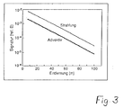
- the slope "a” is the extinction coefficient, which can be used as a direct measure of the visibility (see FIG. 3).
- the extinction coefficient can therefore only be determined in the case of single scatter, regardless of the type of fog, using conventional methods, i.e. regardless of whether there is radiation fog or advective fog, for example.
- the ratio of double scattering to single scattering changes depending on the type of fog, ie this ratio is greater in the case of advective fog than in the case of radiation fog.
- this ratio between single scattering and double scattering cannot be determined in conventional methods, since only a sum of single and double scattered light is received by the receiver.
- laser light backscattered from the lidar is additionally received by a second receiving channel and this second receiving channel is oriented at a divergent, acute tilt angle to the first transmitting channel.
- a first device in which a second receiver is additionally provided, which is oriented so that it receives backscattered light through a second reception channel and this second reception channel at a divergent, acute angle to the first transmission channel is aligned.
- a second device can be used to carry out the method according to the invention, in which the receiver can be moved back and forth between the alignment with the first and the second reception channel, wherein in the latter alignment it receives backscattered light through the second reception channel and this second receiving channel is oriented at a divergent, acute tilt angle to the first transmitting channel.
- the transmit and receive channels run side by side and at a distance from each other because the transmitter or receivers and the receivers are arranged next to each other or one above the other.
- the acute tilt angle between the reception channels and the associated transmission channels is dimensioned such that predominantly multiply scattered light is received in the reception channels, in particular double-scattered light.
- the share of in double-scattered light received on the receiving channels can be, for example, 95%.
- the tilt angle is to be understood as the angle which is included by an imaginary extension of a respective tilted reception channel and the respectively associated transmission channel.
- the tilt angles are relatively small and can be, for example, 0.33 °.
- the tilt angles are optimized so that they are so large that no or only a relatively small proportion of single-scattered light is received by the tilted receiving channel, while the intensity of the double and more than twice-scattered light is high.
- a tilt angle optimized in this way mainly double-scattered light is received.
- the larger the tilt angle is selected the smaller the total light intensity received, while the proportion of more than twice scattered light increases. On the one hand, this increases the pulse width undesirably, which makes the evaluation more difficult, and on the other hand, the evaluation is less accurate due to the low light intensity of the received light.
- the extinction is calculated back from the received lidar signals by means of an evaluation method, for which purpose a ratio is formed between the lidar signal received by the first receiving channel and the lidar signal received by the second receiving channel and thereby a Ratio between the sum of the intensity of the total backscattered light and the more than simply scattered light is formed.
- a sum of single and multiple scattered light is received through the parallel receiving channel, while predominantly, for example 90% or 95% and more, two or more scattered light is received in the "tilted" receiving channel .
- a ratio between the intensity of the light received by the parallel reception channel and the intensity of the light can be transmitted determine the type of fog received by the tilted receiving channel and then determine the range of vision using an evaluation method adapted to this type of fog.
- a second transmission channel can be provided, which is aligned parallel to the first transmission channel.
- exactly one receive channel is assigned to each transmit channel.
- a third reception channel is provided, which is aligned parallel and axisymmetrically with respect to the first transmission channel or an imaginary line running in the middle between the two transmission channels, only backscattered light with a first polarization plane being received by the first reception channel , while only backscattered light is received by the third receiving channel with a second polarization plane which is perpendicular to the first polarization plane.
- a fourth reception channel can advantageously be provided, which is aligned axially symmetrically with respect to the second reception channel with respect to the first transmission channel or an imaginary line running in the middle between the two transmission channels.
- a third and a fourth transmission channel can advantageously be provided, one of the transmission channels being assigned to one of the reception channels.
- any number of transmission and reception channels can be provided, it not being necessary for each reception channel to be assigned its own transmission channel.
- Several transmit channels can also be assigned to one transmit channel using a multiplexer.
- the absorbance is calculated back from the received lidar signals by means of an advantageous development of the method according to the invention, for which purpose an Ratio between the value of the lidar signal received by the first receiving channel to the value of the lidar signal received by the second receiving channel and a ratio between the value of the lidar signal received by the third receiving channel to the value of the fourth receiving channel received lidar signal is formed.
- the polarization plane of the backscattered light is detected on the basis of a comparison of the values of the received lidar signals between the first and third and the second and fourth reception channels, and conclusions are thus drawn about the type of scattering medium, i.e. of the aerosol.
- Aerosol means any type of scattering medium, such as fog, ice fog, smoke, dust or a mixture thereof.
- the acute tilt angle between the first and second receiving channels is dimensioned such that more than 90% of twice scattered light is received by the second receiver.
- a transmitter is not permanently assigned to each receiver, a transmitter can advantageously be assigned alternately to a plurality of receivers by means of a multiplexer, which alternately switch the respective individual receivers to readiness to receive.
- the receivers can be provided with polarization filters aligned in such a way that the first and third receivers only receive light with a horizontal polarization plane and the second and fourth receivers only receive light with a vertical polarization plane or vice versa, the transmitters in each case being linearly polarized Send light with a defined polarization plane.
- the polarization plane of the transmitted, linearly polarized light is known and the polarity plane of the received, linearly polarized light can be determined, the strength of the depolarization can be determined, and conclusions can thus be drawn about the type of fog .
- any other polarization plane of the respective polarization filter is also possible, for example that both polarization planes are arranged at an angle of + 45 ° or -45 ° to the vertical or horizontal, or that the two polarization planes are not perpendicular to one another, but only one Include angles with each other, which, however, unnecessarily complicates the calculation of the polarization plane of the received, backscattered light.
- Each transmitter advantageously has a laser diode which emits monochromatic light with a laser pulse frequency of 10 ... 50 Khz.
- the wavelength of the emitted laser light should be in the range of the size of the fog particles.
- the pulse frequency should be as large as possible for the reason that a large number of evaluable pulses are received per unit of time, so that even with a low light output (this may for safety reasons Laser light should not be too large) due to the large number of pulses that can be evaluated, a high measuring accuracy is achieved.
- the transmitter can emit laser light with a pulse length of 40 ns, a power of 0.006 mJ, a wavelength of 860 nm, a divergence of 5 mrad and a diameter of the light beam of 4 cm.
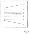
- FIG. 1 and FIG. 2 show schematic representations of an exemplary embodiment of a visual range sensor, four transmission channels and four reception channels being provided.
- Transmitting and receiving channels are understood here to mean spatially extending, imaginary channels through which laser light is transmitted or received.
- the corresponding transmitters and receivers and thus also the respective transmit and receive channels are arranged at a distance from one another.
- the transmit and receive channels run parallel to one another or a “tilted” receive channel E1 or E4 with a slight divergence of, for example, 0.33 ° to the respective transmit channel S1 or S4.
- These divergence angles are referred to as so-called tilt angles and in FIG. 1 are those angles which are included between the transmission channel S1 and the reception channel E1 or between the transmission channel S4 and the reception channel E4.
- each reception channel E1 to E4 is assigned a special one of the transmission channels S1 to S4, through which pulsed laser light is transmitted by a transmitter.
- the transmitters are usually each provided with a laser diode.
- the receivers which receive the laser light are arranged at the end of the reception channels.
- the transit time of a light pulse and the intensity of the received light are measured.
- the acute tilt angle between the reception channels E2, E4 and the associated transmission channels S2, S4 is dimensioned so that in the reception channels E2 and E4 predominantly multiple scattered light is received, especially double-scattered light.
- the proportion of the double-scattered light received in the reception channels E2 and E4 can be, for example, 95%.
- the tilt angles are relatively small and can be, for example, 0.33 °.
- the tilt angles are optimized in such a way that they are so large that no or only a negligible proportion of single-scattered light is received by the tilted receiving channel, while the intensity of the double and more than twice-scattered light is high. With a tilt angle optimized in this way, mainly double-scattered light is received.
- the receiving channels E1 and E2 receive only horizontally polarized light, while the receiving channels E3 and E4 receive only vertically polarized light.
- the “distance” is to be understood as the distance traveled by the laser light pulse.
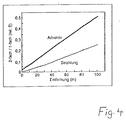
- the ratio of the intensities of the received, double-scattered light to the single-scattered light depends to a large extent on the type of fog and, depending on the type of fog, a better visibility is simulated to varying degrees. 4 shows the ratio of the intensities of double-scattered light to single-scattered light using an example of radiation nebula and advective nebula.
- the signal from the receiving channel E3 is used, through which a sum of single and multiple-scattered light is received, and the signal from the receiving channel E4, through which only multiple-scattered light, mainly double-scattered light, is received.
- the ratio of the signal from the receiving channel S4 to the signal from the receiving channel S3 is formed, after which the fog type is inferred on the basis of a database.
- the signature ⁇ is first determined, whereupon the actual value of ⁇ is determined using a database and on the basis of the first determination of ⁇ in combination with the already determined type of fog.
- the ratio of the signal from the receiving channel S4 to the signal from the receiving channel S3 and the first, as it were provisionally determined value of ⁇ (and thus the visibility) are fed to a database and the second and final determination of the visibility is made by means of an iteration performed.
- a backscatter value can be inferred from the signal Si3 on the basis of the light backscattered by the third reception channel E3, ie on the basis of (A + B), while the signal Si4 on the basis of the light backscattered by the fourth reception channel E4, ie on the basis of C. , indicates the degree of double spread. It also shows from calculations that in the event that C / (A + B) ⁇ 0.2 the visibility is more than 100 m. With both values, ie with the backscatter value and the degree of double spreading, a) the type of fog and b) the visibility can be deduced. Using a table (A, B, C) and the theoretical signals, a measurement curve can be simulated with the specified visibility.
- all transmitters can transmit light with the same polarization level through the mutually parallel transmission channels S1 to S4, for example horizontally polarized light, while one tilted receiver E2 or E4 only horizontally polarized light and the other tilted receiver E4 or E2 receives only perpendicularly polarized light, and one of the parallel receiver E1 or E3 only receives horizontally polarized light and the other parallel receiver E3 or E1 only receives vertically polarized light.
- the type of fog is additionally determined on the basis of the determination of the polarization plane of the received light, i.e. due to the nature and strength of the depolarization caused by the fog.
- This is possible because different nebulas cause different depolarization. For example, there is a strong depolarization in the case of ice crystals, while a low depolarization takes place in the case of water droplets. This additional information about the depolarization therefore also allows conclusions to be drawn about the type of fog and is therefore also included in the measurement of the visibility.
- FIG. 6 An evaluation method taking into account the depolarization level of the backscattered light is shown in FIG. 6, wherein the ratio of signals Si3 / Si1 is formed, the signal Si1 due to the light backscattered by the first receiving channel E1 and the signal Si3 due to the light received by the third receiving channel E3 backscattered light is formed, the polarization planes of the two receivers E1 and E3 being perpendicular to one another.
- the ratio is less than or equal to 0.2, the following applies Si3 / Si1 ⁇ 0.2 , there is in any case no ice mist and it is evaluated according to a method I and a subsequent method II, while otherwise, for example in the case of snow or other precipitation, is only evaluated according to method II, unless at the same time it applies that this is due to the tilted receiving channel E2 received light generated signal Si2 does not have the same value as the signal Si1.
- the signal Si2 has the same value as the signal Si1, there would be ice mist and with the help of a database and on the basis of additional information about the weather, the temperature and the humidity would then be evaluated by means of a correction function according to a method III.
- the evaluation method taking into account the depolarization level of the backscattered light, as shown in FIG. 6, could therefore be described as an evaluation method with a preselection of the fog types.
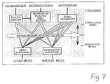
- a further improvement of the evaluation can be achieved by an expert system which uses further information, such as the driving speed, and makes a correction according to the respective driving speed.
- an expert system is shown in FIG. 7.
Landscapes
- Physics & Mathematics (AREA)
- Engineering & Computer Science (AREA)
- General Physics & Mathematics (AREA)
- Computer Networks & Wireless Communication (AREA)
- Electromagnetism (AREA)
- Radar, Positioning & Navigation (AREA)
- Remote Sensing (AREA)
- Life Sciences & Earth Sciences (AREA)
- Health & Medical Sciences (AREA)
- Chemical & Material Sciences (AREA)
- Analytical Chemistry (AREA)
- Biochemistry (AREA)
- General Health & Medical Sciences (AREA)
- Immunology (AREA)
- Pathology (AREA)
- Optical Radar Systems And Details Thereof (AREA)
- Investigating Or Analysing Materials By Optical Means (AREA)
Applications Claiming Priority (2)
| Application Number | Priority Date | Filing Date | Title |
|---|---|---|---|
| DE4324308 | 1993-07-20 | ||
| DE4324308A DE4324308C1 (de) | 1993-07-20 | 1993-07-20 | Verfahren zum Bestimmen der Sichtweite bei dichtem Nebel sowie Sichtweitensensor |
Publications (3)
| Publication Number | Publication Date |
|---|---|
| EP0635731A2 true EP0635731A2 (fr) | 1995-01-25 |
| EP0635731A3 EP0635731A3 (fr) | 1995-05-24 |
| EP0635731B1 EP0635731B1 (fr) | 1998-12-23 |
Family
ID=6493262
Family Applications (1)
| Application Number | Title | Priority Date | Filing Date |
|---|---|---|---|
| EP94109743A Expired - Lifetime EP0635731B1 (fr) | 1993-07-20 | 1994-06-23 | Méthode et capteur pour déterminer la limite de visibilité dans le brouillard épais |
Country Status (2)
| Country | Link |
|---|---|
| EP (1) | EP0635731B1 (fr) |
| DE (2) | DE4324308C1 (fr) |
Cited By (10)
| Publication number | Priority date | Publication date | Assignee | Title |
|---|---|---|---|---|
| EP0978718A1 (fr) * | 1998-08-07 | 2000-02-09 | Deutsches Zentrum für Luft- und Raumfahrt e.V. | Procédé de détection de fumée au moyen d'un système à Lidar |
| DE102004004190A1 (de) * | 2004-01-28 | 2005-08-25 | Opel Eisenach Gmbh | Kraftfahrzeug mit einer Nebelschlussleuchte und einem Fahrassistenzsystem |
| DE102010062378A1 (de) | 2010-12-03 | 2012-06-06 | Robert Bosch Gmbh | Verfahren und Einrichtung für die Umfelderfassung mit einer Lidarsensorik |
| CN102621102A (zh) * | 2012-03-31 | 2012-08-01 | 中国科学院安徽光学精密机械研究所 | 基于ccd激光雷达的水平能见度的测量方法 |
| CN110542909A (zh) * | 2019-09-03 | 2019-12-06 | 北京领骏科技有限公司 | 一种大气能见度检测方法及电子设备 |
| WO2021005105A1 (fr) * | 2019-07-09 | 2021-01-14 | Sony Semiconductor Solutions Corporation | Systèmes, dispositifs, et procédés d'imagerie |
| CN113176586A (zh) * | 2021-03-25 | 2021-07-27 | 北京大学 | 一种雨滴测量方法及固态面阵激光雨滴谱仪 |
| CN114325761A (zh) * | 2021-12-31 | 2022-04-12 | 象谱信息产业有限公司 | 一种通过激光雷达团雾深度检测系统及方法 |
| US11467595B2 (en) * | 2012-09-26 | 2022-10-11 | Waymo Llc | Wide-view LIDAR with areas of special attention |
| DE102019135884B4 (de) | 2019-06-03 | 2026-02-19 | Preh Gmbh | Verfahren zur Nebeldetektion unter Ausnutzung unterschiedlicher Sende-Empfangssituationen und zugehörige Nebeldetektionseinrichtung |
Families Citing this family (7)
| Publication number | Priority date | Publication date | Assignee | Title |
|---|---|---|---|---|
| IT1281017B1 (it) * | 1995-11-07 | 1998-02-11 | Magneti Marelli Spa | Sistema di telerilevamento ottico anticollisione per veicoli. |
| RU2069885C1 (ru) * | 1996-03-01 | 1996-11-27 | Йелстаун Корпорейшн Н.В. | Способ наблюдения объектов при пониженной освещенности и устройство для его осуществления |
| DE10149768A1 (de) * | 2001-10-09 | 2003-04-17 | Ibeo Automobile Sensor Gmbh | Sichtweitenbestimmung |
| DE202008005019U1 (de) * | 2008-04-10 | 2009-08-20 | Mann+Hummel Gmbh | Zylinderkopfhaube für einen Zylinderkopf einer Brennkraftmaschine |
| DE102013219344A1 (de) * | 2013-09-26 | 2015-03-26 | Conti Temic Microelectronic Gmbh | Verfahren zur Bestimmung des Abstandes eines Objektes mittels eines polarisationsmodulierten Sendelichtstrahls |
| DE102015112103B4 (de) * | 2015-07-24 | 2025-09-18 | Preh Gmbh | Detektionsvorrichtung zur Nebelerkennung für ein Kraftfahrzeug |
| DE102017219610A1 (de) * | 2017-11-06 | 2019-05-09 | Robert Bosch Gmbh | Verfahren zur Bestimmung eines Typus eines Hydrometeors |
Family Cites Families (7)
| Publication number | Priority date | Publication date | Assignee | Title |
|---|---|---|---|---|
| US4479053A (en) * | 1981-03-11 | 1984-10-23 | The United States Of America As Represented By The Administrator Of The National Aeronautics And Space Administration | Focal plane array optical proximity sensor |
| DE3244358C2 (de) * | 1982-12-01 | 1984-10-04 | Daimler-Benz Ag, 7000 Stuttgart | Einrichtung zur Erfassung von Hindernissen als Rangierhilfe beim Einparken oder Wenden eines Kraftfahrzeuges |
| DE3930272A1 (de) * | 1988-10-05 | 1990-04-19 | Impulsphysik Gmbh | Lidar |
| DE4016973C1 (fr) * | 1990-02-24 | 1991-06-13 | Eltro Gmbh, Gesellschaft Fuer Strahlungstechnik, 6900 Heidelberg, De | |
| EP0490029B1 (fr) * | 1990-12-11 | 1995-12-06 | Daimler-Benz Aktiengesellschaft | Appareil pour améliorer la visibilité en particulier dans les véhicules |
| CA2053758C (fr) * | 1991-10-18 | 2001-01-02 | Luc R. Bissonnette | Lidar a diffusion multiple |
| DE4233379C1 (de) * | 1992-10-05 | 1994-03-31 | Leica Ag Heerbrugg | Verfahren und Vorrichtung zur relativen Sichtweitenbestimmung |
-
1993
- 1993-07-20 DE DE4324308A patent/DE4324308C1/de not_active Expired - Fee Related
-
1994
- 1994-06-23 EP EP94109743A patent/EP0635731B1/fr not_active Expired - Lifetime
- 1994-06-23 DE DE59407517T patent/DE59407517D1/de not_active Expired - Fee Related
Cited By (13)
| Publication number | Priority date | Publication date | Assignee | Title |
|---|---|---|---|---|
| EP0978718A1 (fr) * | 1998-08-07 | 2000-02-09 | Deutsches Zentrum für Luft- und Raumfahrt e.V. | Procédé de détection de fumée au moyen d'un système à Lidar |
| DE102004004190A1 (de) * | 2004-01-28 | 2005-08-25 | Opel Eisenach Gmbh | Kraftfahrzeug mit einer Nebelschlussleuchte und einem Fahrassistenzsystem |
| DE102010062378B4 (de) | 2010-12-03 | 2024-06-06 | Robert Bosch Gmbh | Verfahren und Einrichtung für die Umfelderfassung mit einer Lidarsensorik |
| DE102010062378A1 (de) | 2010-12-03 | 2012-06-06 | Robert Bosch Gmbh | Verfahren und Einrichtung für die Umfelderfassung mit einer Lidarsensorik |
| CN102621102A (zh) * | 2012-03-31 | 2012-08-01 | 中国科学院安徽光学精密机械研究所 | 基于ccd激光雷达的水平能见度的测量方法 |
| US11467595B2 (en) * | 2012-09-26 | 2022-10-11 | Waymo Llc | Wide-view LIDAR with areas of special attention |
| DE102019135884B4 (de) | 2019-06-03 | 2026-02-19 | Preh Gmbh | Verfahren zur Nebeldetektion unter Ausnutzung unterschiedlicher Sende-Empfangssituationen und zugehörige Nebeldetektionseinrichtung |
| WO2021005105A1 (fr) * | 2019-07-09 | 2021-01-14 | Sony Semiconductor Solutions Corporation | Systèmes, dispositifs, et procédés d'imagerie |
| US12298405B2 (en) | 2019-07-09 | 2025-05-13 | Sony Semiconductor Solutions Corporation | Imaging systems, devices and methods |
| CN110542909A (zh) * | 2019-09-03 | 2019-12-06 | 北京领骏科技有限公司 | 一种大气能见度检测方法及电子设备 |
| CN113176586A (zh) * | 2021-03-25 | 2021-07-27 | 北京大学 | 一种雨滴测量方法及固态面阵激光雨滴谱仪 |
| CN113176586B (zh) * | 2021-03-25 | 2023-05-02 | 北京大学 | 一种雨滴测量方法及固态面阵激光雨滴谱仪 |
| CN114325761A (zh) * | 2021-12-31 | 2022-04-12 | 象谱信息产业有限公司 | 一种通过激光雷达团雾深度检测系统及方法 |
Also Published As
| Publication number | Publication date |
|---|---|
| DE4324308C1 (de) | 1994-12-22 |
| EP0635731A3 (fr) | 1995-05-24 |
| EP0635731B1 (fr) | 1998-12-23 |
| DE59407517D1 (de) | 1999-02-04 |
Similar Documents
| Publication | Publication Date | Title |
|---|---|---|
| EP0635731B1 (fr) | Méthode et capteur pour déterminer la limite de visibilité dans le brouillard épais | |
| DE69212966T2 (de) | Radareinrichtung mit laser | |
| EP3324203B1 (fr) | Module de télémétrie laser présentant une analyse de polarisation | |
| EP2300852B1 (fr) | Dispositif lidar doppler à réception directe et procédé associé | |
| DE69915581T2 (de) | Dreidimensionales messverfahren und vermessungsinstrument welches das verfahren verwendet | |
| EP0033870B1 (fr) | Procédé pour la mesure de la visibilité oblique | |
| DE102010003843A1 (de) | Entfernungsmessgerät mit homogenisierender Messauswertung | |
| DE102005015914A1 (de) | Kombinierte Laser-Höhen- und Bodengeschwindigkeits-Messvorrichtung | |
| WO2013024167A1 (fr) | Procédé et dispositif de détermination des propriétés caractéristiques d'une particule transparente | |
| DE2819321C3 (de) | Laser-Entfernungs- und Geschwindigkeitsmesser | |
| DE1523179B2 (de) | Geraet zum bestimmen der relativen geschwindigkeit zwischen zwei objekten | |
| DE3930272C2 (fr) | ||
| EP4083660A1 (fr) | Dispositif lidar doppler destiné à la détection des situations de vent et/ou de turbulences | |
| EP1085346B1 (fr) | Procédé pour mesurer la distance d'un objet, de particules atmospheriques et similaires utilisant des signaux de Lidar ou Radar à laser | |
| EP0392172B1 (fr) | Système laser-radar | |
| DE4005919C2 (de) | Verfahren und Anordnung zum Ermitteln der Sichtweite für Autofahrer beim Auftreten von Nebel | |
| DE3701296C1 (de) | Anordnung zum Bestimmen der Position eines Laserstrahles in einem streuenden Medium | |
| DE1946264B2 (de) | Geraet zur messung der sichtweite bei nebel | |
| DE2831305A1 (de) | Vorrichtung zur messung einer komponente der windgeschwindigkeit | |
| DE69006898T2 (de) | Verfahren zur Laserwarnung und Laserwarnsensor. | |
| DE102008045366B4 (de) | Vorrichtung und Verfahren zur Geschwindigkeitsmessung | |
| EP0218126B1 (fr) | Procédé pour la mesure par ultrasons de vitesse de fluide | |
| DE10149423B4 (de) | Verfahren und Vorrichtung zur Messung von Entfernungen in optisch trüben Medien | |
| DE102018201735B4 (de) | Vorrichtung und Verfahren zum Ermitteln eines Abstandes eines bewegten Objekts | |
| DE1623422B2 (de) | Lichtelektrischer messverfahren |
Legal Events
| Date | Code | Title | Description |
|---|---|---|---|
| PUAI | Public reference made under article 153(3) epc to a published international application that has entered the european phase |
Free format text: ORIGINAL CODE: 0009012 |
|
| AK | Designated contracting states |
Kind code of ref document: A2 Designated state(s): DE FR GB IT |
|
| PUAL | Search report despatched |
Free format text: ORIGINAL CODE: 0009013 |
|
| AK | Designated contracting states |
Kind code of ref document: A3 Designated state(s): DE FR GB IT |
|
| 17P | Request for examination filed |
Effective date: 19951124 |
|
| 17Q | First examination report despatched |
Effective date: 19960910 |
|
| GRAG | Despatch of communication of intention to grant |
Free format text: ORIGINAL CODE: EPIDOS AGRA |
|
| GRAG | Despatch of communication of intention to grant |
Free format text: ORIGINAL CODE: EPIDOS AGRA |
|
| GRAH | Despatch of communication of intention to grant a patent |
Free format text: ORIGINAL CODE: EPIDOS IGRA |
|
| RAP3 | Party data changed (applicant data changed or rights of an application transferred) |
Owner name: DEUTSCHES ZENTRUM FUER LUFT- UND RAUMFAHRT E.V. Owner name: BAYERISCHE MOTOREN WERKE AKTIENGESELLSCHAFT |
|
| GRAH | Despatch of communication of intention to grant a patent |
Free format text: ORIGINAL CODE: EPIDOS IGRA |
|
| GRAA | (expected) grant |
Free format text: ORIGINAL CODE: 0009210 |
|
| AK | Designated contracting states |
Kind code of ref document: B1 Designated state(s): DE FR GB IT |
|
| REF | Corresponds to: |
Ref document number: 59407517 Country of ref document: DE Date of ref document: 19990204 |
|
| ET | Fr: translation filed | ||
| ITF | It: translation for a ep patent filed | ||
| GBT | Gb: translation of ep patent filed (gb section 77(6)(a)/1977) |
Effective date: 19990224 |
|
| PLBE | No opposition filed within time limit |
Free format text: ORIGINAL CODE: 0009261 |
|
| STAA | Information on the status of an ep patent application or granted ep patent |
Free format text: STATUS: NO OPPOSITION FILED WITHIN TIME LIMIT |
|
| 26N | No opposition filed | ||
| REG | Reference to a national code |
Ref country code: GB Ref legal event code: 732E |
|
| REG | Reference to a national code |
Ref country code: FR Ref legal event code: TP |
|
| REG | Reference to a national code |
Ref country code: GB Ref legal event code: IF02 |
|
| PGFP | Annual fee paid to national office [announced via postgrant information from national office to epo] |
Ref country code: DE Payment date: 20050527 Year of fee payment: 12 |
|
| PGFP | Annual fee paid to national office [announced via postgrant information from national office to epo] |
Ref country code: GB Payment date: 20050613 Year of fee payment: 12 |
|
| PGFP | Annual fee paid to national office [announced via postgrant information from national office to epo] |
Ref country code: FR Payment date: 20050621 Year of fee payment: 12 |
|
| PG25 | Lapsed in a contracting state [announced via postgrant information from national office to epo] |
Ref country code: GB Free format text: LAPSE BECAUSE OF NON-PAYMENT OF DUE FEES Effective date: 20060623 |
|
| PGFP | Annual fee paid to national office [announced via postgrant information from national office to epo] |
Ref country code: IT Payment date: 20060630 Year of fee payment: 13 |
|
| PG25 | Lapsed in a contracting state [announced via postgrant information from national office to epo] |
Ref country code: DE Free format text: LAPSE BECAUSE OF NON-PAYMENT OF DUE FEES Effective date: 20070103 |
|
| GBPC | Gb: european patent ceased through non-payment of renewal fee |
Effective date: 20060623 |
|
| REG | Reference to a national code |
Ref country code: FR Ref legal event code: ST Effective date: 20070228 |
|
| PG25 | Lapsed in a contracting state [announced via postgrant information from national office to epo] |
Ref country code: FR Free format text: LAPSE BECAUSE OF NON-PAYMENT OF DUE FEES Effective date: 20060630 |
|
| PG25 | Lapsed in a contracting state [announced via postgrant information from national office to epo] |
Ref country code: IT Free format text: LAPSE BECAUSE OF NON-PAYMENT OF DUE FEES Effective date: 20070623 |