EP0635803A2 - Verfahren und Gerät zur Bildverarbeitung - Google Patents
Verfahren und Gerät zur Bildverarbeitung Download PDFInfo
- Publication number
- EP0635803A2 EP0635803A2 EP94109395A EP94109395A EP0635803A2 EP 0635803 A2 EP0635803 A2 EP 0635803A2 EP 94109395 A EP94109395 A EP 94109395A EP 94109395 A EP94109395 A EP 94109395A EP 0635803 A2 EP0635803 A2 EP 0635803A2
- Authority
- EP
- European Patent Office
- Prior art keywords
- labeled images
- labeled
- sorting
- images
- image
- Prior art date
- Legal status (The legal status is an assumption and is not a legal conclusion. Google has not performed a legal analysis and makes no representation as to the accuracy of the status listed.)
- Withdrawn
Links
Images





Classifications
-
- G—PHYSICS
- G06—COMPUTING OR CALCULATING; COUNTING
- G06V—IMAGE OR VIDEO RECOGNITION OR UNDERSTANDING
- G06V30/00—Character recognition; Recognising digital ink; Document-oriented image-based pattern recognition
- G06V30/40—Document-oriented image-based pattern recognition
Definitions
- the present invention relates to a method for image processing and an apparatus thereof, which sorts a plurality of labeled images and carries out certain processes by specifying any labeled images which are sorted. More particularly, the present invention relates to a method and an apparatus for sorting plural labeled images which are labeled differently so as to specify exactly aimed labeled images.
- the image obtained by taking a picture image is subjected to binarization and converted to a binary image, and the binary image is subjected to the labelling process to extract and label the image areas of the respective objects.
- the respective image areas extracted by labelling that is, the labeled images are sorted by feature parameters of the respective images such as areas or the coordinates on centers of gravity, and a specified labeled image is designated to carry out a process for recognition.
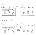
- Fig. 11 (1) and (2) show one embodiment of sorting by areas conventionally.
- Fig. 11 (1) shows an image 20 obtained by taking a picture image of the characters, and three of the same character "A" having different areas are in a row.
- the image 20 of these characters is raster-scanned as shown by arrows in the drawing to extract labeled image a1, a2 and a3 of the characters.
- the respective labeled images a1, a2 and a3 are labeled in the order of extraction.
- the character in the center having the largest area are labeled L1
- the character on the left having the smallest area is labeled L2
- the character on the right having a middle-sized area is labeled L3.
- the feature parameters of labeled images a1 - a3 are measured and stored in predetermined storage areas in RAM.
- the feature parameter of the labeled image a2 which is labeled L1 is stored to the storage area relating to label L1 in RAM
- the feature parameter of the labeled image a1 which is labeled L2 is stored to the storage area relating to label L2
- the feature parameter of the labeled image a3 which is labeled L3 is stored in the storage area relating to label L3, in sequence.
- these labeled images a1, a2 and a3 are sorted by areas.
- the sorting mentioned here means a rearranging of the data in RAM so that the feature parameters of the labeled image a2 having the largest area, the feature parameters of the labeled image a3 having the second largest area, and the feature parameters of the labeled image a1 having the smallest area are stored in the storage areas relating to labels L1, L2, and L3 respectively.
- it means a modification of the labels allotted to respective labeled images a1 - a3, and Fig. 11 (2) shows the relations between labeled images a1 - a3 and the labels L1 - L3 after the sorting.
- the central labeled image a2 is specified, and the feature parameters of the labeled image a2 are read out from the storage area relating to the label L1.
- Fig. 12 (1) and (2) show one embodiment of sorting by X coordinates on the centers of gravity conventionally.
- Fig. 12 (1) shows an image 21 obtained by taking a picture image of characters, and in the image three of the same character "A" having almost the same size are in a row.
- the image 21 of these characters is raster-scanned as shown by arrows in the drawing to extract labeled images a4, a5 and a6 of the characters.
- the labeled images a4, a5 and a6 are labeled in the order of extraction.
- the character in the center is labeled L1
- the character on the left is labeled L2
- the character on the right is labeled L3.
- the feature parameters of respective labeled images a4 - a6 are measured, and are stored in a predetermined storage areas in RAM in the same manner as described above.
- the feature parameter of the labeled image a5 which is labeled L1 is stored in the storage area relating to label L1
- the feature parameter of the labeled image a4 which is labeled L2 is stored in the storage area relating to label L2
- the feature parameter of the labeled image a6 which is labeled L3 is stored in the storage area relating to label L3, in sequence.
- the respective labeled images a4, a5 and a6 are sorted by X coordinates on the centers of gravity.
- the sorting mentioned here means a rearranging of the data in RAM so that the feature parameters of the labeled image a4 having the smallest X coordinate, the labeled image a5 having the second smallest X coordinate, and the labeled image a6 having the largest X coordinate are stored in the storage areas in RAM relating to labels L1, L2, and L3 respectively.
- Fig. 12 (2) shows the relations between respective labeled images a4 - a6 and the labels L1 - L3 after the sorting.
- the labeled image having the smallest X coordinate is designated, the labeled image a4 on the left end is specified, and the feature parameter of the labeled image a4 is read out from the storage area relating to the label L1.
- each labeled image in the image of examination is allotted the same label as the corresponding labeled image in the model image. So it is judged whether the object is good or not by reading out the feature parameters of the labeled images which are labeled the same from the RAM and comparing their parameters.
- the present invention provides a method for image processing, in which labeled images which are labeled differently are sorted, said method being carried out by the steps of dividing the respective labeled images into groups according to their positional relations, and sorting respective labeled images belonging to each group by their positions within the group.
- respective labeled images which are labeled differently are divided into groups according to their positional relations, and respective labeled images belonging to each group are sorted by respective positions. So even if plural labeled images have the same area, or are located in plural columns and plural rows, it is possible to sort respective images in a certain order according to the groups and the arrangement order of labeled images within each group, to specify the objectives exactly, and to perform a proper measurement.
- said step of dividing the labeled images into groups comprises dividing the respective labeled images which are labeled differently into groups according to their positional relations in the vertical direction, and said step of sorting the labeled images belonging to each group comprises sorting respective labeled images belonging to each group by the positions of the labeled images in the horizontal direction.
- respective labeled images are divided into groups according to the positional relations in the direction of Y axis, and images in each group are sorted. So objects such as characters and figures which continue in the horizontal direction can be processed in sequence.
- said step of dividing the labeled images into groups may comprise dividing the respective labeled images which are labeled differently into groups according to their positional relations in the horizontal direction, and said step of sorting the labeled images belonging to each group may comprise sorting respective labeled images belonging to each group by the positions of the labeled images in the vertical direction.
- respective labeled images are divided into groups according to their positional relations in the direction of X axis, and labeled images belonging to each group are sorted. So objects such as characters and figures which continue in the vertical direction can be processed in sequence.
- an apparatus to perform the image processing method described above comprises measuring means for measuring positions in the image of the respective labeled images which are labeled differently, judging means for discriminating the positional relations between respective labeled images whose positions have been measured by said measuring means, grouping means for dividing the labeled images into groups according to the positional relations between the labeled images discriminated by the judging means, and sorting means for sorting respective labeled images belonging to each group by positions of the labeled images measured by the measuring means.
- Said measuring means preferably, measures the positions in the image of the respective labeled images which are labeled differently according to the coordinates in the centers of gravity of the labeled images, therefore the positions of labeled images can be obtained simply.
- Said judging means preferably, comprises means for sorting the respective labeled images which are labeled differently by the positions of the labeled images measured by the measuring means, means for setting up areas circumscribing the respective labeled images in the order of the sorting and measuring the positions at the corresponding end portions of each circumscribed area, and means for judging the positional relations between the respective labeled images by comparing the positions at the respective end portions of the circumscribed areas.
- respective labeled images are sorted by measured positions, and the circumscribed area is set up for respective labeled images in the order of sorting, to discriminate the relative positional relations of respective labeled images according to the positions at the corresponding end portions of the respective circumscribed areas. So grouping of labeled images can be easily and correctly carried out.
- an image processing apparatus which comprises noise removing means for excluding labeled images whose areas are smaller than a predetermined value as noise, among the respective labeled images, measuring means for measuring positions in the image of remaining labeled images whose areas are larger than the predetermined value, judging means for discriminating the relative positional relations between the remaining labeled images whose positions have been measures by said measuring means, grouping means for dividing the remaining labeled images into groups according to the relative positional relations discriminated by the judging means, and sorting means for sorting respective labeled images belonging to each group by the positions of the labeled images measured by the measuring means.
- noise removing means for excluding labeled images whose areas are smaller than a predetermined value as noise, among the respective labeled images
- measuring means for measuring positions in the image of remaining labeled images whose areas are larger than the predetermined value
- judging means for discriminating the relative positional relations between the remaining labeled images whose positions have been measures by said measuring means
- grouping means for dividing the remaining label
- Fig. 1 shows a structure of an image processing apparatus according to one embodiment of the present invention.
- numeral 1 represents a TV camera which is positioned to take a picture image of the object 10 from the upper direction, and the picture signals of this TV camera is sent to a binarization circuit 3 through an interface circuit 2 including an A/D converting circuit therein.
- the binarization circuit 3 converts the picture signals to binary signals based on a predetermined threshold, and outputs binary image data to the image memory 4.
- Said object 10 in this embodiment has plural characters or figures in plural columns and plural rows printed on its surface, and the image processing apparatus examines if there is any indistinct or uneven portion with regard to specific character or figure located on predetermined column and a predetermined row.
- the image processing apparatus of the present invention can be used for recognition or examination of objects other than printed patterns.
- CPU 5 which is the main control body of this apparatus, is connected to said image memory 4, ROM 6, RAM 7 as well as a display 8 such as CRT and a keyboard 9.
- Said RAM 7 includes storage areas for storing various data such as a feature parameter storage table and a group data storage table which will be described later, and the data stored in RAM 7 are accessed by CPU 5 as necessary.
- CPU 5 reads out data from RAM 7 and writes data to RAM 7 based on the programs stored in ROM 6, extracts image areas of printed patterns in the image data stored in the image memory 4 to label the image ares, and sorts respective labeled images in a certain order, and judges whether the object is good or not according to the feature parameters of respective labeled images or some specific labeled images.
- Fig. 2 shows an example of labelling in an image obtained by taking a picture image of said object 10.
- labeled images A1 - A8 are shown, which are obtained by taking a picture image of circular printed patterns arranged in 4 columns and 2 rows.
- g1 - g8 represent the centers of gravity of respective labeled images A1 - A8.
- Said CPU 5 scans the image 14 in the direction shown by arrows in the drawing, segments the image area of respective printed matters to extract the labeled images A1 - A8, extracts the data relating to the length in the horizontal direction (run length) of respective labeled images A1 - A8 as feature parameters, and stores the feature parameters in RAM 7.
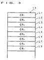
- Fig. 3 shows a feature parameter storage table provided in RAM 7 for storing the feature parameters of the extracted respective labeled images A1 - A8.
- L1 - L8 represent individual areas in the feature parameter storage table 15, and CR1 - CR8 represent the feature parameters of the labeled images A1 - A8, respectively.
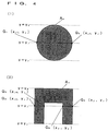
- the feature parameters CR1 - CR8 mean groups of plural data relating to run lengths extracted in the respective labeled images A1 - A8. Concretely speaking, the data of each run length is represented by encoding the positions at the end points of respective images.
- Fig. 4 (1) and (2) show an example of extraction of run lengths of labeled images.
- each data such as area, the peripheral length, and the position of the center of gravity of the labeled image A n , is properly calculated by this feature parameter CR n .
- an area L1 is for storing data relating to the labeled image first extracted by the raster scanning among the image areas A1 - A8, and in the same manner the feature parameters of labeled images are stored in the areas L2 - L8 in the order of the labelling.
- said respective labeled images are extracted in order of A1, A2, A3, A4 A8, A6, A5, and A7, and the feature parameters of the labeled images are stored in the order.
- data in said feature parameter storage table 15 is sorted in ascending order of the Y coordinates of the centers of gravity of respective labeled images, and rectangles circumscribing the respective labeled images are set up, and the positional relations of respective labeled images are extracted from the Y coordinates on the upper edges and the lower edges of the respective rectangles to divide the data into groups. Furthermore, the data in each group is sorted within the group in ascending order of the X coordinates of the center of gravity.
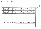
- Fig. 5 shows an example of setting the group data storage table 16 in RAM 7.
- LB m1 - LB m represent addresses in the feature parameter storage table 15 (the addresses correspond to L1, L2, ... in the above Fig. 3) which store the feature parameters of the labeled images which are determined to belong to the group G m
- TH m1 and TH m2 represent the maximum value and the minimum value respectively, both are set as an index for grouping, as be described later.
- the feature parameters of respective labeled images are sorted by the above method, and stored in certain areas in RAM 7. Then, the image data of the objects of examination is taken in sequence, and the obtained images are subjected to the labelling and the sorting in the same manner described above, and the feature parameters of respective labeled images or some specific labeled images are compared with the corresponding stored parameters of the model image to judge whether the objects are good or not.
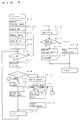
- Fig. 6 shows a control procedure from taking a picture image to examination which are carried out by said CPU 5 according to the program, at step 1 (shown by "ST1" in the drawing) to step 20.
- CPU 5 activates TV camera 1 to take a picture image of an object 10.
- the picture signals output from the TV camera 1 are converted to digital signals, and further converted to the binary signals in the binarization circuit 3, and then the binary image data are stored in the image memory 4.
- CPU 5 subjects the binary image data stored in the image memory 4 to labelling to extract image areas of respective printed patterns. After the labelling process, CPU 5 extracts said run lengths data of respective labeled images in the order of labels, and stores the data in said feature parameter storage table 15 in RAM 7 (step 2).
- CPU 5 checks the areas of the respective labeled images A1 - A8. If the areas of any label images are below the predetermined value, CPU 5 determines the labeled images to be equivalent to noise, deletes the data of the labeled images in said feature parameter storage table 15 so that it is excluded from objectives of the following procedures and renews the memory by advancing the data in the subsequent areas in sequence.
- CPU 5 compares the Y coordinates Y G of the centers of gravity of the labeled images A1 - A8, and sorts the respective data of the feature parameter storage table 15 in ascending order of Y G (step 4).
- CPU 5 judges whether the value of said variable i is an initialized value or not (step 8). Since the judgement at step 8 is "YES" at first, CPU 5 proceeds to step 9, to establishes the first group G1 for the labeled image. And CPU 5 establishes the maximum value TH i1 , and the minimum value TH i2 to said coordinates Y i1 and Y i2 respectively, as the range of the Y coordinate, in order to extract the labeled images which are assigned to the first group (step 10).
- CPU 5 adds 1 to the variable i to return to step 6, and judges whether the value of the variable i exceeds the number N of the labeled images A1 - A8. At present, i. e. after the first increment, this judgement becomes "NO", and CPU 5 sets a rectangle which circumscribes the labeled image whose Y coordinate of the center of gravity is second smallest (the labeled image whose data is stored in the area L2 of said feature parameter storage table 15) to calculate the Y coordinates on the upper edge and the lower edge, Y i1 , and Y i2 of the rectangle.
- step 8 Since the value of the variable i becomes "2" as the result of the first increment, the judgement at the next step 8 is "NO", and CPU 5 proceeds to step 12 to check whether the Y coordinates Y i1 and Y i2 on the upper edge and the lower edge of the rectangle circumscribing the second labeled image is included in the range of the Y coordinate of the first group G1.
- Fig. 7 shows the group checking method concretely.
- the Y coordinate Y i1 on the upper edge of the second circumscribed rectangle 12 is in the range of the Y coordinate of the first group, that is, between the maximum value TH11 and the minimum value TH12. Therefore, the second labeled image is determined to be included in the first group G1.
- CPU 5 compares the Y coordinates on the upper edge and the lower edge of the circumscribed rectangle with the maximum value TH11 and the minimum value TH12, respectively, to renew the range of the group G1.
- CPU 5 proceeds to step 9 to establish a new group.
- the eight labeled images A1 - A8 are divided into the group of the 1st row and the group of the 2nd row.
- step 6 When this grouping has been completed, the judgement at step 6 becomes "YES", and CPU 5 proceeds to step 16 to extract the respective labeled images belonging to the first group G1 by referring to said group data storage area 16, and to sort the data of the labeled images of the group in ascending order of the X values X G of the centers of gravity. Then, the data of the respective labeled images belonging to the second group G2, are sorted in the same manner in ascending order of the X coordinate X G of the centers of gravity.
- Fig. 8 shows the data stored in the feature parameter storage area 15 after the sorting has been completed.
- the feature parameters CR1 - CR4 of the labeled images A1 - A4 on the first row are stored in the areas L1 - L4 respectively, and the feature parameters CR5 - CR8 of the labeled images A5 - A8 on the second row are stored in the areas L5 - L8, respectively, in ascending order of the X coordinates of the centers of gravity.
- step 17 when the above processes are carried out for the image of a good model, the judgement at step 17 becomes "YES", and CPU 5 stores the feature parameters of respective labeled images in the stored order in certain storage areas in RAM 7 (step 18).
- step 17 when the procedure is carried out for the image of an object, the judgement at step 17 becomes "NO", and CPU 5 specifies respective labeled images in sequence or specifies one or plural specific labeled images, based on a set up condition (step 19).
- CPU 5 specifies the second labeled image on the second row at step 19, the labeled image A6 in Fig. 2 will be identified. Then, CPU 5 calculates area of the labeled image A6 from the data in RAM 7 (the data in area L6 of the feature parameter storage table 15), and compares the area with the stored data, that is, the area of the labeled image stored sixthly relating to the model image, and judge whether any indistinct or uneven portion is present or not (step 20).
- the judging at step 20 may be carried out by pattern matching.
- the sorting is not only in ascending order, but also in descending order.
- the data of respective labeled images may be divided into groups based on the X coordinates at first, and labeled images in each group may be sorted based on the Y coordinates.
- the Y coordinates of the corresponding two edges of the rectangle circumscribing the labeled images are used as parameters for grouping. But it is possible to provide other modification.
- the data of respective labeled images may be divided into groups by checking whether the X coordinate or the Y coordinate of center of gravity is in a certain range or not.
- grouping and sorting are carried out by means of the X and Y coordinates, but sorting may be carried out by means of, for example, the polar coordinates.
- Fig. 9 shows an example of labelling in an image obtained by taking a picture image of a cylindrical object from the upper direction.
- G0 in the drawing represents the center of gravity of the object
- P represents a reference point for extracting the angles of respective labeled images B1 - B9 to G0.
- the run lengths are extracted as the feature parameter of each labeled image, and stored in the feature parameter storage table 15 in RAM 7.
- sorting corresponding to the step 4 in said Fig. 6 is carried out in respect of angles ⁇ between the respective lines L which go through the centers of gravity g of respective labeled images and said G0, and the line M (which goes through said reference point P and G0).
- CPU 5 first determines these angles ⁇ for respective labeled images B1 - B11 in sequence, sorts the data of respective labeled images in ascending order of angle ⁇ , and sets up areas which circumscribe respective labeled images.
- Fig. 10 shows an example in which a circumscribed area is set up for the labeled image B n .
- This circumscribed area is comprised of tangents k1 and k2, which go through said G0 and circumscribe the labeled image B n , and the circumscribed arcs r1 and r2 which circumscribe the labeled image at the nearest point q1 and at the farthest point q2 from G0 respectively.
- these arcs, r1 and r2 are determined by the distance l1 l2 between each point q1, q2 and G0, and the angles ⁇ 1, ⁇ 2 of said respective tangents k1, k2 to said line M.
- CPU 5 sets up the circumscribed area for respective labeled images in the order of sorting, and divides respective labeled images into groups by the distance l1 l2 between the arcs r1, r2 and the center of gravity G0, After this grouping is completed, CPU 5 sorts respective labeled images within each group by said angles ⁇ 1, ⁇ 2, in the order of grouping.
Landscapes
- Engineering & Computer Science (AREA)
- Computer Vision & Pattern Recognition (AREA)
- Artificial Intelligence (AREA)
- Physics & Mathematics (AREA)
- General Physics & Mathematics (AREA)
- Multimedia (AREA)
- Theoretical Computer Science (AREA)
- Image Analysis (AREA)
- Image Processing (AREA)
Applications Claiming Priority (2)
| Application Number | Priority Date | Filing Date | Title |
|---|---|---|---|
| JP172544/93 | 1993-06-18 | ||
| JP17254493 | 1993-06-18 |
Publications (2)
| Publication Number | Publication Date |
|---|---|
| EP0635803A2 true EP0635803A2 (de) | 1995-01-25 |
| EP0635803A3 EP0635803A3 (de) | 1995-06-07 |
Family
ID=15943854
Family Applications (1)
| Application Number | Title | Priority Date | Filing Date |
|---|---|---|---|
| EP94109395A Withdrawn EP0635803A3 (de) | 1993-06-18 | 1994-06-17 | Verfahren und Gerät zur Bildverarbeitung. |
Country Status (1)
| Country | Link |
|---|---|
| EP (1) | EP0635803A3 (de) |
Cited By (1)
| Publication number | Priority date | Publication date | Assignee | Title |
|---|---|---|---|---|
| WO2001046909A1 (en) * | 1999-12-21 | 2001-06-28 | Snap-On Technologies, Inc. | Method and apparatus of automatically identifying faults in a machine vision measuring system |
Family Cites Families (3)
| Publication number | Priority date | Publication date | Assignee | Title |
|---|---|---|---|---|
| US4377803A (en) * | 1980-07-02 | 1983-03-22 | International Business Machines Corporation | Algorithm for the segmentation of printed fixed pitch documents |
| JPS63268081A (ja) * | 1987-04-17 | 1988-11-04 | インタ−ナショナル・ビジネス・マシ−ンズ・コ−ポレ−ション | 文書の文字を認識する方法及び装置 |
| US5113451A (en) * | 1989-10-16 | 1992-05-12 | Vlsi Technology, Inc. | Method for labelling polygons |
-
1994
- 1994-06-17 EP EP94109395A patent/EP0635803A3/de not_active Withdrawn
Cited By (3)
| Publication number | Priority date | Publication date | Assignee | Title |
|---|---|---|---|---|
| WO2001046909A1 (en) * | 1999-12-21 | 2001-06-28 | Snap-On Technologies, Inc. | Method and apparatus of automatically identifying faults in a machine vision measuring system |
| US6323776B1 (en) | 1999-12-21 | 2001-11-27 | Snap-On Technologies, Inc. | Method and apparatus of automatically identifying faults in a machine vision measuring system |
| KR100722489B1 (ko) * | 1999-12-21 | 2007-05-29 | 스넵-온 테크놀로지스 인코포레이티드 | 기계 관찰 측정 시스템의 고장을 자동적으로 식별하는 방법 및 장치 |
Also Published As
| Publication number | Publication date |
|---|---|
| EP0635803A3 (de) | 1995-06-07 |
Similar Documents
| Publication | Publication Date | Title |
|---|---|---|
| US5544259A (en) | Apparatus and method for separating handwritten characters by line and word | |
| US5325447A (en) | Handwritten digit normalization method | |
| US5583949A (en) | Apparatus and method for use in image processing | |
| US4998285A (en) | Character recognition apparatus | |
| US4183013A (en) | System for extracting shape features from an image | |
| US5590220A (en) | Bending point extraction method for optical character recognition system | |
| US4072928A (en) | Industrial system for inspecting and identifying workpieces | |
| US5034991A (en) | Character recognition method and system | |
| US4481664A (en) | Process for inspecting objects showing patterns with dimensional tolerances and reject criteria varying with the locations of said patterns and apparatus and circuits for carrying out said process | |
| EP0145725B1 (de) | Verfahren und vorrichtung zur echtzeit-hochgeschwindigkeitsprüfung von objekten zum identifizieren oder erkennen bekannter und unbekannter teile davon, einschliesslich fehler und dergleichen | |
| EP0063454B1 (de) | Verfahren zum Erkennen von maschinell kodierten Zeichen | |
| EP0138445B1 (de) | Verfahren und Anlage für die Segmentierung von Zeichendarstellungen | |
| US5048096A (en) | Bi-tonal image non-text matter removal with run length and connected component analysis | |
| CN111402316B (zh) | 一种基于去伪环节的图像中椭圆快速检测方法 | |
| US4630308A (en) | Character reader | |
| EP0436819B1 (de) | Handschrifterkennung mit Verwendung von jeweils zwischen zwei Klassen unterscheidenden Massnahmen | |
| WO1996024114A2 (en) | Method and apparatus for separating foreground from background in images containing text | |
| EP0266140B1 (de) | Optische Buchstabenerkennung durch Bilden und Auswerten von Matrizen geographischer Merkmale | |
| US4860376A (en) | Character recognition system for optical character reader | |
| US5825925A (en) | Image classifier utilizing class distribution maps for character recognition | |
| US5058177A (en) | Method for inspection of protruding features | |
| EP0432937B1 (de) | Gerät zur Erkennung handgeschriebener Zeichen | |
| CN105095937A (zh) | 一种基于直线聚类的圆形阵列图形码的视觉识别方法 | |
| EP0156343A2 (de) | Verfahren und Anlage zum Vergleichen von Teilmustern | |
| US5119441A (en) | Optical character recognition apparatus and method using masks operation |
Legal Events
| Date | Code | Title | Description |
|---|---|---|---|
| PUAI | Public reference made under article 153(3) epc to a published international application that has entered the european phase |
Free format text: ORIGINAL CODE: 0009012 |
|
| 17P | Request for examination filed |
Effective date: 19940718 |
|
| AK | Designated contracting states |
Kind code of ref document: A2 Designated state(s): DE FR IT NL |
|
| PUAL | Search report despatched |
Free format text: ORIGINAL CODE: 0009013 |
|
| AK | Designated contracting states |
Kind code of ref document: A3 Designated state(s): DE FR IT NL |
|
| RHK1 | Main classification (correction) |
Ipc: G06F 15/70 |
|
| 17Q | First examination report despatched |
Effective date: 19981013 |
|
| STAA | Information on the status of an ep patent application or granted ep patent |
Free format text: STATUS: THE APPLICATION IS DEEMED TO BE WITHDRAWN |
|
| 18D | Application deemed to be withdrawn |
Effective date: 19990224 |