EP0635822A2 - Tête magnétique magnétorésistive à films minces - Google Patents
Tête magnétique magnétorésistive à films minces Download PDFInfo
- Publication number
- EP0635822A2 EP0635822A2 EP94111195A EP94111195A EP0635822A2 EP 0635822 A2 EP0635822 A2 EP 0635822A2 EP 94111195 A EP94111195 A EP 94111195A EP 94111195 A EP94111195 A EP 94111195A EP 0635822 A2 EP0635822 A2 EP 0635822A2
- Authority
- EP
- European Patent Office
- Prior art keywords
- width
- magnetic
- film
- lower shield
- thin
- Prior art date
- Legal status (The legal status is an assumption and is not a legal conclusion. Google has not performed a legal analysis and makes no representation as to the accuracy of the status listed.)
- Withdrawn
Links
Images


Classifications
-
- G—PHYSICS
- G11—INFORMATION STORAGE
- G11B—INFORMATION STORAGE BASED ON RELATIVE MOVEMENT BETWEEN RECORD CARRIER AND TRANSDUCER
- G11B5/00—Recording by magnetisation or demagnetisation of a record carrier; Reproducing by magnetic means; Record carriers therefor
- G11B5/127—Structure or manufacture of heads, e.g. inductive
- G11B5/33—Structure or manufacture of flux-sensitive heads, i.e. for reproduction only; Combination of such heads with means for recording or erasing only
- G11B5/39—Structure or manufacture of flux-sensitive heads, i.e. for reproduction only; Combination of such heads with means for recording or erasing only using magneto-resistive devices or effects
- G11B5/3903—Structure or manufacture of flux-sensitive heads, i.e. for reproduction only; Combination of such heads with means for recording or erasing only using magneto-resistive devices or effects using magnetic thin film layers or their effects, the films being part of integrated structures
-
- G—PHYSICS
- G11—INFORMATION STORAGE
- G11B—INFORMATION STORAGE BASED ON RELATIVE MOVEMENT BETWEEN RECORD CARRIER AND TRANSDUCER
- G11B5/00—Recording by magnetisation or demagnetisation of a record carrier; Reproducing by magnetic means; Record carriers therefor
- G11B5/48—Disposition or mounting of heads or head supports relative to record carriers ; arrangements of heads, e.g. for scanning the record carrier to increase the relative speed
- G11B5/488—Disposition of heads
- G11B5/4886—Disposition of heads relative to rotating disc
Definitions
- This invention relates to a magnetoresistive thin-film magnetic head employing a magnetoresistive film having its resistivity varied in response to the recording magnetic field of a magnetic recording medium and detecting a change in resistance of the magnetoresistive film as a reproduction output voltage.
- a magnetoresistance effect magnetic head which detects, as a reproduction output voltage, a change in resistance of a magnetoresistive element having its resistivity varied in accordance with the magnetic field does not have the medium-velocity-dependent reproduction output, thus allowing a high reproduction output to be produced even at a low medium velocity.
- the magnetoresistance effect magnetic head is noted as a magnetic head for realizing a greater capacity with the small-size hard disk.
- the magnetoresistive element is hereinafter referred to simply as an MR head.
- a magnetoresistive thin-film magnetic head in which a thin-film MR element is sandwiched by a lower shield core and an upper shield core as magnetic paths in reproduction is formed on a slider member.
- the magnetoresistive thin-film magnetic head is hereinafter referred to simply as an MR thin-film head.
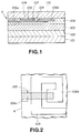
- a vertical MR thin-film head for example, includes a non-magnetic substrate 101, an insulation layer 102, a soft magnetic film as a lower shield magnetic body 103 and an insulation layer 104 are stacked in this order from the bottom, as shown in Figs.1 and 2.
- an MR element 105 is arranged with its longitudinal direction perpendicular to a magnetic recording facing surface (head surface a) and with its one end surface exposed to the head surface a.
- a front-end electrode 106a and a rear-end electrode 106b for supplying sense currents to both ends of the MR element 105 are formed.
- a bias conductor 108 is formed, longitudinally traversing the underlying MR element 105. Then, an insulation layer 109 and a soft magnetic film as an upper shield magnetic body 110 are sequentially stacked on the entire surface.
- the conventional MR thin-film head is thus formed.
- the rear-end electrode 106b is serially connected to the bias conductor 108.
- the MR thin-film head having the structure in which the MR element 105 is held between the upper and lower shield magnetic bodies 110, 103, recording density dependence of the reproduction output can be improved, compared with other MR head lacking the upper and lower shield magnetic bodies 110, 103.
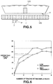
- the upper and lower shield magnetic bodies 110, 103 magnetically shielding the MR element 105 are formed in parallel to face each other, and both portions exposed to the head surface a of the upper and lower shield magnetic bodies 110, 103 have width of 100 plus tens of ⁇ m, as shown in Fig.3.
- the presence of the crosstalk component S prevents a reduction in the track pitch and affects the phase margin where the track recording density is high and the output level is low, thus deteriorating the S/N ratio of the original signal component.
- the crosstalk component S is superposed on the signals, deteriorating the quality of the servo signal and the tracking signal.
- the upper and lower shield magnetic bodies 110, 103 have the width of 100 plus tens of ⁇ m, not less than 15 tracks other than the target tracks exist within the width, causing the crosstalk component to be superposed on the original signal to be outputted. Consequently, the S/N ratio of reproduction signals is deteriorated, and reliability of the servo signals is lowered.
- a magnetoresistive thin-film magnetic head having a magnetoresistive film having resistivity varied in response to a recording magnetic field from a magnetic recording medium.
- the magnetoresistive thin-film magnetic head of the present invention includes a magnetoresistive element having magnetoresistance effect, which is exposed to a recording medium facing surface, and upper and lower shield magnetic bodies formed of soft magnetic layers, which magnetically shield the magnetoresistive element with a non-magnetic layer held between them in a direction of film thickness.
- one or both of the upper and lower shield magnetic bodies have at least width of a portion thereof exposed to the recording medium facing surface, not smaller than an effective track width and not greater than four times a track pitch.
- length in the direction of depth determined by the width may be greater than formation length of the magnetoresistive element.
- the width may be not smaller than the effective track width and not greater than the track pitch, and the length in the direction of depth determined by the width may be not smaller than 9% of maximum recording wavelength.
- the width of the portion exposed to the recording medium facing surface in one or both of the upper and lower shield magnetic bodies is not smaller than the effective track width and not greater than four times the track pitch, the number of tracks within the width, particularly tracks other than the tracks for reproduction, can be reduced.
- the maximum number of tracks included within the width is 4.
- the crosstalk value rapidly decreases, as shown in Fig.6. Accordingly, with the above-described structure, the crosstalk component from the tracks other than the tracks for reproduction can be significantly reduced.
- Fig.1 is a cross-sectional view showing essential portions of a conventional MR thin-film head.
- Fig.2 is a plan view showing essential portions of the conventional MR thin-film head.
- Fig.3 is a perspective view showing essential portions of the conventional MR thin-film head.
- Fig.4 is a graph showing off-track properties of the conventional MR thin-film head.
- Fig.5 is a plan view showing tracks which fall within the shield width of the conventional MR head in reading out information from a recording medium.
- Fig.6 is a graph showing the relation between the number of tracks within the shield width and crosstalk.
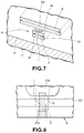
- Fig.7 is a perspective view showing essential portions of a first embodiment of a magnetoresistive thin-film magnetic head according to the present invention, hereinafter referred to the MR thin-film head of the first embodiment.
- Fig.8 is a plan view showing essential portions of the MR thin-film magnetic head of the first embodiment, with an upper shield magnetic body excluded therefrom.
- Fig.9 is a graph showing the relation between bit shift and crosstalk.
- Fig.10 is a perspective view showing essential portions of a second embodiment of the magnetoresistive thin-film magnetic head according to the present invention, hereinafter referred to the MR thin-film head of the second embodiment.
- Fig.11 is a plan view showing essential portions of the MR thin-film magnetic head of the second embodiment.
- the MR thin-film head of the first embodiment has a magnetoresistive element 1, referred to simply as the MR element hereinafter, and a lower shield magnetic body 2 and an upper shield magnetic body 3 as magnetic paths in reproduction which hold the MR element 1 between them, as shown in Fig.7.
- the MR element 1 has its one longitudinal end exposed to a surface facing a magnetic recording medium, that is, a recording medium facing surface a, as shown in Fig.8.
- a forward end electrode 21a is formed in an end portion, that is, the forward end, on the side of the recording medium facing surface of the MR element 1 and a rear end electrode 21b of soft magnetic films is formed in a portion having a predetermined distance from the forward end.
- the forward end electrode 21a and the rear end electrode 21b are formed of soft magnetic films.
- the forward end electrode 21a and the rear end electrode 21b are formed for the purpose of causing a sense current to flow in the longitudinal direction of the MR element 1, that is, in the direction orthogonal to the recording medium facing surface a.
- the forward end electrode 21a since the forward end electrode 21a is separately formed, flattening is carried out after formation of the insulation layer 14 so that the upper surface of the forward end electrode 21a is exposed and is then electrically connected to the upper shield magnetic body 3. Consequently, a second reproduction gap is formed by the forward end electrode 21a.
- an area of the MR element 1 between the rear end of the forward end electrode 21a and the forward end of the rear end electrode 21b exhibits magnetoresistance effect, and this area defines a sensor 1a of the MR element 1.
- a bias conductor 22 for applying a bias magnetic field to the MR element 1 is formed in a traversing manner above the MR element 1.
- the portion exposed to the recording medium facing surface a of the lower shield magnetic body 2 has a width D1, referred to simply as the shield width D1, smaller than the shield width D2 of the upper shield magnetic body 3, as shown in Fig.7.
- the shield width of the shield magnetic body is narrowed, turbulence of anisotropy is generated.
- a soft magnetic film of, for example, sendust having isotropic anisotropy and broad magnetic domain walls is used as the shield magnetic body, the turbulence of anisotropy can be avoided.
- the soft magnetic film of sendust is formed on the non-magnetic substrate 11 by sputtering, with the insulation layer 12 provided between them. Then, the soft magnetic film is partly removed by ion etching, thus forming the lower shield magnetic body 2 of the narrower shield width D1.
- the shield width D1 of the lower shield magnetic body 2 is caused to be not smaller than the effective track width and not greater than four times the track pitch, in consideration of the results of experiment as shown in Figs.5 and 6. Also, in the first embodiment, the lower shield magnetic body 2 is caused to have the length in the direction of depth of the portion determined by the shield width D1 which is greater than the formation length of the MR element.
- the shield width of the lower shield magnetic body 2 not smaller than the effective track width and not greater than four times the track pitch, with the crosstalk value shown by a broken line will cause the crosstalk component to be approximately 20 dB or less in reproducing high frequency signals.
- the shield width of the lower shield magnetic body 2 not smaller than the effective track width and not greater than three times the track pitch, with the crosstalk value shown by a dashed line is preferred for restricting the crosstalk component to approximately 20 dB or less in reproducing low frequency signals.
- the shield width D2 of the upper shield magnetic body 3 is caused to be normal, and the shield width D1 of the lower shield magnetic body 2 is restricted to be not smaller than the effective track width and not greater than four times the track pitch, with the length in the direction of depth of the portion determined by the shield width D1 caused to be greater than the formation length of the MR element 1, in the portions exposed to the recording medium surface a of the upper and lower shield magnetic bodies 3, 2.
- the number of tracks within the shield width D1 particularly the tracks other than the tracks for reproduction, can be reduced.
- the shield width D1 is caused to be not greater than four times the track pitch, the maximum number of tracks included within the shield width D1 is 4. In this case, if the number of tracks within the shield width D1 is 4 or less, the crosstalk value is rapidly lowered, as shown in Fig.6. Consequently, with the above-described structure, the crosstalk component from the tracks other than the tracks for reproduction can be significantly reduced.
- the S/N ratio of reproduction signals and reliability of servo signals can be improved, and reproduction signals of a lower error rate and servo signals of less errors can be produced.
- the crosstalk component can be reduced by 5 dB or more compared with conventional technique, and the effects on the bit shift can also be reduced.
- the shield width D2 of the upper shield magnetic body 3 is at a conventional value while the shield width D1 of the lower shield magnetic body 2 is narrower, for the following reasons. That is, it is necessary to sputter and then anneal sendust as the component material of the shield magnetic body at 520°C for the sendust to have magnetic properties.
- the lower shield magnetic body 2 is to have its shield width narrowed, it can be annealed as described above without affecting the MR element 1 yet to be formed.
- the upper shield magnetic body 3 is annealed with its shield width D2 narrowed, the MR element 1 is simultaneously annealed, causing possible deterioration of reproduction properties of the MR element 1.
- the width of the lower shield magnetic body 2 formed of sendust is caused to be narrower, it is annealed before formation of the MR element 1.
- effective annealing can be implemented without affecting properties of the MR element 1, thus producing the MR thin-film head exempt from deterioration of properties.
- the MR thin-film head of the second embodiment though having substantially the same structure as the MR thin-film head of the first embodiment, is different in that the shield width D1 of the lower shield magnetic body is caused to be not smaller than the effective track width and not greater than the track pitch and in that the length in the direction of depth from the recording medium facing surface a of the lower shield magnetic body, that is, recess width, is determined by a value d expressed as follows.
- the shield width D2 of the upper shield magnetic body 3 is caused to be normal while the shield width D1 of the lower shield magnetic body 2 is caused to be not smaller than the effective track width and not greater than the track pitch, with the length or the recess width d in the direction of depth determined by the shield width D1 caused to be not smaller than 9% of the maximum recording wavelength, in the portions exposed to the recording medium facing surface a of the upper and lower shield magnetic bodies 2, 3. Therefore, as in the first embodiment, the crosstalk component from the tracks other than the tracks for reproduction can be significantly reduced. Consequently, the S/N ratio of reproduction signals and reliability of servo signals can be improved, and the reproduction signals of a lower error rate and servo signals of less errors can be produced.
- the crosstalk component can be decreased by approximately 5 dB or more compared with the conventional technique, and the effects on the bit shift can also be reduced.
- the shield width D1 of the lower shield magnetic body 2 formed of sendust is caused to be narrower, it is annealed before formation of the MR element 1.
- effective annealing can be implemented without affecting properties of the MR element 1, thus producing the MR thin-film head exempt from deterioration of properties.
- the MR thin-film head of the present invention is not limited to the above first and second embodiments, and that materials other than sendust, the narrower shield width of the upper shield magnetic body 3, or the narrower shield width both of the upper and lower shield magnetic bodies 2, 3 can be employed.
- the magnetoresistive thin-film magnetic head including the magnetoresistive element having magnetoresistance effect and exposed to the recording medium facing surface and the upper and lower shield magnetic bodies of soft magnetic layers magnetically shielding the magnetoresistive element with the non-magnetic layer between them in the direction of film thickness, at least the portion exposed to the recording medium facing surface of one or both of the upper and lower shield magnetic bodies has the width not smaller than the effective track width and not greater than four times the track pitch. Therefore, the crosstalk component superposed on the original signal component to be outputted can be reduced, and the S/N ratio of reproduction signals and reliability of servo signals can be improved.
- the magnetoresistive thin-film magnetic head even though the width of the portion exposed to the recording medium facing surface is caused to be not smaller than the effective track width and not greater than the track pitch, with the length in the direction of depth determined by the width caused to be not smaller than 9% of the maximum recording wavelength, in one or both of the upper and lower shield magnetic bodies, the crosstalk component superposed on the original signal component to be outputted can be reduced, and the S/N ratio of reproduction signals and reliability of servo signals can be improved.
Landscapes
- Engineering & Computer Science (AREA)
- Manufacturing & Machinery (AREA)
- Magnetic Heads (AREA)
Applications Claiming Priority (2)
| Application Number | Priority Date | Filing Date | Title |
|---|---|---|---|
| JP178689/93 | 1993-07-20 | ||
| JP5178689A JPH0737228A (ja) | 1993-07-20 | 1993-07-20 | 磁気抵抗効果型薄膜磁気ヘッド |
Publications (2)
| Publication Number | Publication Date |
|---|---|
| EP0635822A2 true EP0635822A2 (fr) | 1995-01-25 |
| EP0635822A3 EP0635822A3 (fr) | 1996-08-07 |
Family
ID=16052832
Family Applications (1)
| Application Number | Title | Priority Date | Filing Date |
|---|---|---|---|
| EP94111195A Withdrawn EP0635822A3 (fr) | 1993-07-20 | 1994-07-18 | Tête magnétique magnétorésistive à films minces. |
Country Status (3)
| Country | Link |
|---|---|
| EP (1) | EP0635822A3 (fr) |
| JP (1) | JPH0737228A (fr) |
| KR (1) | KR960015397A (fr) |
Families Citing this family (2)
| Publication number | Priority date | Publication date | Assignee | Title |
|---|---|---|---|---|
| US8419526B1 (en) | 1998-09-22 | 2013-04-16 | Igt | Methods and apparatus for providing tickets from gaming devices and/or lottery terminals |
| AU2001287068A1 (en) | 1998-09-22 | 2002-03-22 | Igt | Methods and apparatus for providing tickets from gaming devices and/or lottery terminals which are not dependent on a players success of the underlying game |
Family Cites Families (6)
| Publication number | Priority date | Publication date | Assignee | Title |
|---|---|---|---|---|
| US3975772A (en) * | 1975-06-02 | 1976-08-17 | International Business Machines Corporation | Double shielded magnetorestive sensing element |
| US4663684A (en) * | 1984-01-27 | 1987-05-05 | Hitachi, Ltd. | Magnetic transducer using magnetoresistance effect |
| EP0262925A3 (fr) * | 1986-09-29 | 1989-07-26 | Hewlett-Packard Company | Ecran pour transducteur |
| JPH01320615A (ja) * | 1988-06-23 | 1989-12-26 | Matsushita Electric Ind Co Ltd | 薄膜磁気ヘッド |
| JP2728487B2 (ja) * | 1989-02-08 | 1998-03-18 | 株式会社日立製作所 | 録再分離複合型磁気ヘッド |
| JPH0512628A (ja) * | 1991-07-02 | 1993-01-22 | Sony Corp | 複合型薄膜ヘツド |
-
1993
- 1993-07-20 JP JP5178689A patent/JPH0737228A/ja not_active Withdrawn
-
1994
- 1994-07-11 KR KR1019940016570A patent/KR960015397A/ko not_active Withdrawn
- 1994-07-18 EP EP94111195A patent/EP0635822A3/fr not_active Withdrawn
Also Published As
| Publication number | Publication date |
|---|---|
| EP0635822A3 (fr) | 1996-08-07 |
| KR960015397A (ko) | 1996-05-22 |
| JPH0737228A (ja) | 1995-02-07 |
Similar Documents
| Publication | Publication Date | Title |
|---|---|---|
| US5901018A (en) | Magnetic tunnel junction magnetoresistive read head with sensing layer as rear flux guide | |
| US6005753A (en) | Magnetic tunnel junction magnetoresistive read head with longitudinal and transverse bias | |
| EP0534791B1 (fr) | Tête magnétique à film mince à effet de magnétorésistance | |
| JPH10269531A (ja) | 磁気抵抗効果型再生ヘッド | |
| US6094328A (en) | Thin-film magnetic head with antiferromagnetic layer and hard magnetic layers arranged to bias a magnetoresistive device | |
| US7170723B2 (en) | Magnetic disk apparatus using magnetic head having magnetoresistive film | |
| JPS61107520A (ja) | 多チヤンネル磁気抵抗効果型磁気ヘツド | |
| JPH03296907A (ja) | 磁気ヘッドおよびその製造方法 | |
| US5808843A (en) | Magnetoresistance effect reproduction head | |
| JPH05135332A (ja) | 磁気抵抗効果再生ヘツドおよびそれを用いた磁気記録装置 | |
| EP0691642B1 (fr) | Tête magnétique de type à effet magnéto-résistant | |
| EP0635822A2 (fr) | Tête magnétique magnétorésistive à films minces | |
| EP0517137B1 (fr) | Tête d'enregistrement magnétique capable de définir une piste étroite et appareil d'enregistrement magnétique l'utilisant | |
| JPH08329426A (ja) | 磁気抵抗効果型ヘッド | |
| JPH10154312A (ja) | 磁気ヘッド及びその製造方法 | |
| US6333840B1 (en) | Magnetic recording apparatus | |
| US5719729A (en) | Magnetic head and recording and reproducing apparatus having an arrangement for improving coincidence between a magnetic center of a read head and physical center of a write head | |
| JP3475868B2 (ja) | 磁気抵抗効果型薄膜磁気ヘッド | |
| JPS58100216A (ja) | 磁気抵抗効果ヘツド | |
| JP3443971B2 (ja) | 磁気記録信号再生方法 | |
| JP3070495B2 (ja) | 磁気抵抗効果型薄膜変換素子 | |
| JPH06267027A (ja) | 磁気抵抗効果型薄膜磁気ヘッド | |
| JP2751653B2 (ja) | 磁気抵抗効果ヘッド | |
| US6278577B1 (en) | Asymmetric recording head for same gap servo optimization | |
| JP3361345B2 (ja) | 磁気記録装置 |
Legal Events
| Date | Code | Title | Description |
|---|---|---|---|
| PUAI | Public reference made under article 153(3) epc to a published international application that has entered the european phase |
Free format text: ORIGINAL CODE: 0009012 |
|
| AK | Designated contracting states |
Kind code of ref document: A2 Designated state(s): DE FR GB |
|
| PUAL | Search report despatched |
Free format text: ORIGINAL CODE: 0009013 |
|
| AK | Designated contracting states |
Kind code of ref document: A3 Designated state(s): DE FR GB |
|
| STAA | Information on the status of an ep patent application or granted ep patent |
Free format text: STATUS: THE APPLICATION IS DEEMED TO BE WITHDRAWN |
|
| 18D | Application deemed to be withdrawn |
Effective date: 19970203 |