EP0635826B1 - Méthode pour copier des données à grande vitesse - Google Patents
Méthode pour copier des données à grande vitesse Download PDFInfo
- Publication number
- EP0635826B1 EP0635826B1 EP94107560A EP94107560A EP0635826B1 EP 0635826 B1 EP0635826 B1 EP 0635826B1 EP 94107560 A EP94107560 A EP 94107560A EP 94107560 A EP94107560 A EP 94107560A EP 0635826 B1 EP0635826 B1 EP 0635826B1
- Authority
- EP
- European Patent Office
- Prior art keywords
- data
- dubbing method
- speed data
- memory
- speed
- Prior art date
- Legal status (The legal status is an assumption and is not a legal conclusion. Google has not performed a legal analysis and makes no representation as to the accuracy of the status listed.)
- Expired - Lifetime
Links
- 238000000034 method Methods 0.000 title claims description 102
- 230000009191 jumping Effects 0.000 claims description 11
- 230000005540 biological transmission Effects 0.000 claims description 7
- 238000013500 data storage Methods 0.000 claims description 6
- 238000013144 data compression Methods 0.000 claims description 2
- 230000005236 sound signal Effects 0.000 description 22
- 230000003287 optical effect Effects 0.000 description 15
- 238000007906 compression Methods 0.000 description 12
- 238000012545 processing Methods 0.000 description 10
- 238000006243 chemical reaction Methods 0.000 description 4
- 230000007423 decrease Effects 0.000 description 3
- 238000004364 calculation method Methods 0.000 description 2
- 230000006835 compression Effects 0.000 description 2
- 238000011084 recovery Methods 0.000 description 2
- 230000004044 response Effects 0.000 description 2
- 230000035939 shock Effects 0.000 description 2
- 230000003044 adaptive effect Effects 0.000 description 1
- 230000003247 decreasing effect Effects 0.000 description 1
- 238000010586 diagram Methods 0.000 description 1
- 238000005516 engineering process Methods 0.000 description 1
- 238000007726 management method Methods 0.000 description 1
- 238000009987 spinning Methods 0.000 description 1
Images


Classifications
-
- G—PHYSICS
- G11—INFORMATION STORAGE
- G11B—INFORMATION STORAGE BASED ON RELATIVE MOVEMENT BETWEEN RECORD CARRIER AND TRANSDUCER
- G11B20/00—Signal processing not specific to the method of recording or reproducing; Circuits therefor
- G11B20/10—Digital recording or reproducing
- G11B20/10527—Audio or video recording; Data buffering arrangements
-
- G—PHYSICS
- G11—INFORMATION STORAGE
- G11B—INFORMATION STORAGE BASED ON RELATIVE MOVEMENT BETWEEN RECORD CARRIER AND TRANSDUCER
- G11B19/00—Driving, starting, stopping record carriers not specifically of filamentary or web form, or of supports therefor; Control thereof; Control of operating function ; Driving both disc and head
- G11B19/02—Control of operating function, e.g. switching from recording to reproducing
- G11B19/04—Arrangements for preventing, inhibiting, or warning against double recording on the same blank or against other recording or reproducing malfunctions
-
- G—PHYSICS
- G11—INFORMATION STORAGE
- G11B—INFORMATION STORAGE BASED ON RELATIVE MOVEMENT BETWEEN RECORD CARRIER AND TRANSDUCER
- G11B27/00—Editing; Indexing; Addressing; Timing or synchronising; Monitoring; Measuring tape travel
- G11B27/02—Editing, e.g. varying the order of information signals recorded on, or reproduced from, record carriers
- G11B27/031—Electronic editing of digitised analogue information signals, e.g. audio or video signals
- G11B27/034—Electronic editing of digitised analogue information signals, e.g. audio or video signals on discs
-
- G—PHYSICS
- G11—INFORMATION STORAGE
- G11B—INFORMATION STORAGE BASED ON RELATIVE MOVEMENT BETWEEN RECORD CARRIER AND TRANSDUCER
- G11B27/00—Editing; Indexing; Addressing; Timing or synchronising; Monitoring; Measuring tape travel
- G11B27/10—Indexing; Addressing; Timing or synchronising; Measuring tape travel
- G11B27/11—Indexing; Addressing; Timing or synchronising; Measuring tape travel by using information not detectable on the record carrier
-
- G—PHYSICS
- G11—INFORMATION STORAGE
- G11B—INFORMATION STORAGE BASED ON RELATIVE MOVEMENT BETWEEN RECORD CARRIER AND TRANSDUCER
- G11B20/00—Signal processing not specific to the method of recording or reproducing; Circuits therefor
- G11B20/10—Digital recording or reproducing
- G11B20/10527—Audio or video recording; Data buffering arrangements
- G11B2020/1062—Data buffering arrangements, e.g. recording or playback buffers
- G11B2020/10805—Data buffering arrangements, e.g. recording or playback buffers involving specific measures to prevent a buffer overflow
-
- G—PHYSICS
- G11—INFORMATION STORAGE
- G11B—INFORMATION STORAGE BASED ON RELATIVE MOVEMENT BETWEEN RECORD CARRIER AND TRANSDUCER
- G11B20/00—Signal processing not specific to the method of recording or reproducing; Circuits therefor
- G11B20/10—Digital recording or reproducing
- G11B20/10527—Audio or video recording; Data buffering arrangements
- G11B2020/1062—Data buffering arrangements, e.g. recording or playback buffers
- G11B2020/10824—Data buffering arrangements, e.g. recording or playback buffers the buffer being used to prevent vibrations or shocks from causing delays
-
- G—PHYSICS
- G11—INFORMATION STORAGE
- G11B—INFORMATION STORAGE BASED ON RELATIVE MOVEMENT BETWEEN RECORD CARRIER AND TRANSDUCER
- G11B2220/00—Record carriers by type
- G11B2220/20—Disc-shaped record carriers
- G11B2220/25—Disc-shaped record carriers characterised in that the disc is based on a specific recording technology
- G11B2220/2525—Magneto-optical [MO] discs
-
- G—PHYSICS
- G11—INFORMATION STORAGE
- G11B—INFORMATION STORAGE BASED ON RELATIVE MOVEMENT BETWEEN RECORD CARRIER AND TRANSDUCER
- G11B2220/00—Record carriers by type
- G11B2220/20—Disc-shaped record carriers
- G11B2220/25—Disc-shaped record carriers characterised in that the disc is based on a specific recording technology
- G11B2220/2525—Magneto-optical [MO] discs
- G11B2220/2529—Mini-discs
-
- G—PHYSICS
- G11—INFORMATION STORAGE
- G11B—INFORMATION STORAGE BASED ON RELATIVE MOVEMENT BETWEEN RECORD CARRIER AND TRANSDUCER
- G11B2220/00—Record carriers by type
- G11B2220/20—Disc-shaped record carriers
- G11B2220/25—Disc-shaped record carriers characterised in that the disc is based on a specific recording technology
- G11B2220/2537—Optical discs
- G11B2220/2545—CDs
-
- G—PHYSICS
- G11—INFORMATION STORAGE
- G11B—INFORMATION STORAGE BASED ON RELATIVE MOVEMENT BETWEEN RECORD CARRIER AND TRANSDUCER
- G11B2220/00—Record carriers by type
- G11B2220/60—Solid state media
- G11B2220/65—Solid state media wherein solid state memory is used for storing indexing information or metadata
Definitions
- the present invention relates to a high-speed data dubbing method for dubbing data transmitted from an external apparatus, such as a compact disk apparatus or other apparatuses, onto a recording medium such as a mini disk or other recording medium at high speeds.
- CD compact disk
- MD mini disk
- the MD recording apparatus compresses inputted digital data into almost one-fifth the size of the data amount. For this reason, suppose that the recording bit rate of the MD recording apparatus is equal to the reproduction bit rate of the CD, it is possible to increase the reproduction bit rate of the CD by almost five times. In other words, data reproduced in the CD reproduction apparatus by using a reproduction bit rate that is almost five times as great as the normal bit rate is stored in a buffer memory, and after accessing and track jumping with respect to a desired recordable area in the MD, the data is read from the buffer memory on demand, and written in the MD. Thus, data dubbing is made from the CD on the reproduction side to the MD on the recording side at high speeds.
- the reproduction bit rate on the reproduction side is N (natural number) times as great as the normal bit rate. For this reason, writing operations and interruptions between them take place very frequently, and space areas in the buffer memory are virtually reduced by one-Nth. Moreover, this results in an increase in the number of the accessing processes and track-jumping processes to desired recordable areas, and during these operations, data is being stored in the buffer memory at the above-mentioned reproduction bit rate. As a result, the space areas in the buffer memory are further reduced. In addition, in the event of an erroneous accessing process or track-jumping process to a desired recordable area, the space areas in the buffer memory are further reduced.
- the high-speed data dubbing method according to the present inventon comprises the steps defined in claim 1.
- the data externally transmitted is stored in the memory. Then, the data stored in the memory is transferred at a transfer speed that is higher than the transmission speed to the respective intermittent recordable areas on the recording medium, and dubbing is made therein.
- the amount of data to be recorded in the recordable areas may be divided, and waiting time may be calculated with respect to each divided amount of data.
- the next recordable area may be one portion of the first recordable area, or may be the second recordable area that is different from the first recordable area.
- the data dubbing is made at high speeds in desired recordable areas on the recording medium by repeating the above-mentioned operation the predetermined number of times.
- an MD (mini disk) apparatus that is used in the high-speed data dubbing method of the present embodiment is mainly constituted of: an MD 1 provided as a magneto-optical recording medium; an optical pickup 2; an RF amplifier 3; an encoder-decoder/signal processing circuit 4; a shock-proof memory controller 5 (hereinafter, referred to as memory controller); a shock-proof memory 6; an audio signal extension-compression circuit 7; a conversion circuit 8; a microcomputer for use in system controlling 9 (hereinafter, referred to as system controller); a servo circuit 10; a driver circuit 11; a spindle motor 12; a feed motor 13; a power on/off circuit 14; a head driving circuit 15; a recording head 16; a switch 19; and a key discrimination circuit 22.
- the optical pickup 2 writes and reads audio data (data) in and out the MD 1.
- the RF amplifier 3 amplifies signals read out by the optical pickup 2.
- the shock-proof memory 6 temporarily stores the audio data.
- the audio signal extension-compression circuit 7 is constituted by an audio signal extension circuit and an audio signal compression circuit, both not shown.
- the conversion circuit 8 is constituted by a D/A converter 8a and an A/D converter 8b.
- the system controller 9 conducts various controlling operations.
- the switch 19 is constituted by a common terminal 19c and contacts 19a and 19b.
- the contact 19b is connected to a CD reproduction apparatus 20.
- the key discrimination circuit 22 has keys (not shown) by which the user enters instructions related to recording.
- the spindle motor 12 and the feed motor 13 are driven by the driver circuit 11.
- the MD 1 is rotatively driven by the spindle motor 12 and the optical pickup 2 is shifted in the radial direction of the MD 1 by the feed motor 13.
- audio data recorded in the MD 1 is read by the optical pickup 2.
- the audio data read out by the optical pickup 2 is amplified by the RF amplifier 3, and transmitted to the encoder-decoder/signal processing circuit 4.
- the RF amplifier 3 generates servo controlling signals such as a focusing error signal, a tracking error signal, etc. in accordance with the audio data read out by the optical pickup 2, and releases these signals to the servo circuit 10.
- the servo circuit 10 controls the driver circuit 11 in accordance with the servo controlling signals from the RF amplifier 3 and a control signal released from the system controller 9. Then, in response to the control signals from the servo circuit 10, the driver circuit 11 drives the optical pickup 2, the spindle motor 12 and the feed motor 13 so as to allow them to activate respective servo operations such as focusing, tracking and spinning.
- the encoder-decoder/signal processing circuit 4 demodulates the signals amplified by the RF amplifier 3, and after executing signal processings, such as error correction, etc. to the signals, transmits them to the memory controller 5.
- the memory controller 5 writes the signals transmitted from the encoder-decoder/signal processing circuit 4 in the shock-proof memory 6.
- the shock-proof memory 6 is provided with an area for storing TOC (Table of Content) information that is separated from recording areas for audio data. Thus, when the MD 1 is loaded, the shock-proof memory 6 promptly stores the TOC information recorded in the MD 1 at a predetermined area therein in the same manner as it records audio data.
- TOC Table of Content
- the memory controller 5 reads necessary TOC information from the shock-proof memory 6 in response to the demand of the system controller 9, and transmits the information to the system controller 9.
- the system controller 9 identifies positions of respective recordable areas on the MD 1 according to the TOC information.
- the audio data read out from the shock-proof memory 6 is transmitted to the audio signal extension-compression circuit 7 through the memory controller 5.
- the audio signal extension circuit (not shown) in the audio signal extension-compression circuit 7 conducts a time-base extension on the audio data in accordance with a predetermined format.
- the audio signal extension-compression circuit 7 releases the audio data from its compressed state, and transmits the resulting audio data to the D/A converter 8a in the conversion circuit 8.
- the D/A converter 8a converts the audio data that has been subjected to the time-base extension into an analog audio signal.
- the analog audio signal is released to an external apparatus through the output terminal 17.
- the system controller 9 controls the power on/off circuit 14 so that the operating current is supplied and stopped to the optical pickup 2, the RF amplifier 3, the encoder-decoder/signal processing circuit 4, the servo circuit 10, and the driver circuit 11.
- recording operations which are conducted in an MD apparatus are classified into two types: analog audio signals externally inputted are recorded on the MD 1; and digital audio signals inputted from an external apparatus such as a CD reproduction apparatus 20 are recorded on the MD 1.
- the key discrimination circuit 22 receives an instruction related to recording that is entered by the user through the keys, it discriminates which type of the recording operation is required, and sends the result of the discrimination to the system controller 9. According to the result of the discrimination, the system controller 9 switches the switch 19. Thus, upon recording, one of the two types of the recording operations is selected and executed.
- the switch 19 is controlled by the system controller 9 so that the common terminal 19c is connected to contact 19a.
- the audio signals are inputted to the A/D converter 8b in the conversion circuit 8 through the audio input terminal 18.
- the audio signals are sent to the audio signal extension-compression circuit 7 through the contact 19a and the common terminal 19c.
- the audio signal compression circuit (not shown) in the audio signal extension-compression circuit 7 conducts a data compression of virtually one-fifth on the digital audio data by utilizing an information compressing technology related to MDs, called ATRAC (Adaptive Transform Acoustic Coding), and sends the compressed audio data to the memory controller 5.
- ATRAC Adaptive Transform Acoustic Coding
- the memory controller 5 writes the audio data sent from the audio signal extension-compression circuit 7 in the shock-proof memory 6.
- the memory controller 5, under control by the system controller 9, reads out the audio data stored in the shock-proof memory 6, and sends it to the encoder-decoder/signal processing circuit 4.
- the encoder-decoder/signal processing circuit 4 conducts operations such as modulation and addition of error-correcting codes on the read-out audio data.
- the system controller 9 controls the memory controller 5 so as to read out TOC information stored in a predetermined region of the shock-proof memory 6. Then, the system controller 9 recognizes positions of recordable areas on the MD1 in accordance with the TOC information, and controls the servo circuit 10 so that the recording head 16 and the optical pickup 2 are driven to a desired recordable area. Further, the head driving circuit 15 modulates the magnetic field of the recording head 16 in accordance with output signals from the encoder-decoder/signal processing circuit 4, and the resulting magnetic field is applied to the MD1.
- the optical pickup 2 applies a laser beam that is stronger than that during reproduction onto a portion on the MD 1 to which the magnetic field is being applied. Thus, the audio data is recorded (dubbed) on the MD 1.
- the system controller 9 controls the memory controller 5 so that the TOC information stored in the shock-proof memory 6 is updated. After the updating process, the system controller 9 conducts managements of the audio data recorded on the MD 1 or other operations by using the updated information as the newest TOC information.
- the switch 19 is controlled by the system controller 9 so that the common terminal 19c is on the 19b side.
- the audio data is sent from the CD reproduction apparatus 20 to the audio signal extension-compression circuit 7 using a bit rate that is higher than the normal reproduction bit rate of the CD 21.
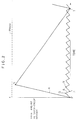
- M MAX represents the maximum allowable amount of data storage of the shock-proof memory 6.
- Characteristic A shows the time-wise variation of the amount of data that remains in the shock-proof memory 6 in the case where the switch 19 is on the contact 19a side (the A/D converter 8b side) (see Fig. 1).
- Characteristic B shows the time-wise variation of the amount of data that remains in the shock-proof memory 6 in the case where the switch 19 is on the contact 19b side (the CD reproduction apparatus 20 side) (see Fig. 1).
- the audio data is sent from the A/D converter 8b to the audio signal extension-compression circuit 7 at the normal transmission speed. Thereafter, the memory controller 5 starts storing the audio data in the shock-proof memory 6 (see point P).
- the amount of data stored in the shock-proof memory 6 reaches an amount of data corresponding to the minimum recording unit of the MD 1, an accessing process to a desired recording portion on the MD 1 is carried out, thereby starting a recording operation of the audio data onto the MD 1 (see point Q).
- the recording operation of the audio data onto the MD 1 is carried out at a bit rate of virtually five times as great as that used when the audio data is inputted to the shock-proof memory 6. For this reason, the amount of data stored in the shock-proof memory 6 decreases at a rate indicated by line QR during the recording operation on the MD 1. More specifically, the amount of data stored in the shock-proof memory 6 decreases at a time-wise rate of change that is greater than that used in the case of storing the audio data in the shock-proof memory 6 (indicated by line PQ).
- the recording operation Upon completion of the recording of the audio data in the amount corresponding the minimum recording unit of the MD 1 (see point R), the recording operation is stopped until the amount of data stored in the shock-proof memory 6 again reaches the amount of data corresponding to the minimum recording unit of the MD 1 (see point V).
- the amount of data to be stored in the shock-proof memory 6 is always kept at a smaller amount in comparison with the maximum allowable amount of data storage M MAX .
- the shock-proof memory 6 is always used with its amount of data close to the empty state. For this reason, even in the event of any disturbance such as a mechanical shock in the MD apparatus, the shock-proof memory 6 makes room for time required for the recovery operation (retrying operation). This makes it possible to provide a highly reliable data dubbing method.
- the digital audio data to be recorded is stored in the shock-proof memory 6 at a bit rate that is, for example, virtually four times as great as the normal reproduction bit rate.
- line PS corresponds to a section wherein the stand-by state of the recording operation and the accessing and track jumping processes with respect to a recording portion take place.
- characteristic B allows the audio data to be stored in the shock-proof memory 6 at a time-wise rate of change virtually four times as great.
- line ST corresponds to a section wherein the audio data read out from the shock-proof memory is written (dubbed) in the MD 1.
- the shock-proof memory 6 allows the MD 1 to successively record more amount of audio data that corresponds to more minimum recording units.
- the more the amount of data is increased the more difficult it becomes for the shock-proof memory 6 to make room for time required for the recovery operation.
- the MD apparatus is less susceptible to the influence; this makes it different from the case of making data dubbing by the use of the A/D converter 8b.
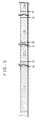
- the MD 1 is provided with recordable areas that are intermittently disposed in such a manner as recordable area (1), recordable area (2), recordable area (3), recordable area (4).... as shown in Fig. 3, if the amount of data to be stored in the shock-proof memory 6 before the start of the recording operation is increased within a range up to M MAX , there is a possibility that an overflow occurs in the shock-proof memory 6.
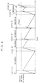
- the reasons for this are explained as follows: At the time when the recording operation is transferred from one recordable area to the next recordable area (see point a, point c and point e in Fig. 3), the amount of data remaining in the shock-proof memory 6 is indefinite (see point a, point c and point e in Fig. 4).
- the audio data is being continuously stored in the shock-proof memory 6.
- the system controller 9 can not record all the audio data in one recording operation; thus, the recordings are made twice in a divided manner.
- the amount of data remaining in the shock-proof memory 6 varies with time as shown in Fig. 4, the amount of data remaining in the shock-proof memory 6 reaches the maximum allowable amount of data storage M MAX at point h after completion of the recording operation onto recordable area (3). Thus, an overflow occurs in the shock-proof memory 6.
- the present embodiment provides the following means.
- the system controller 9 recognizes positions of the recordable areas (1).... on the MD 1, that is, the leading position and rear position of each recordable area. Then, in accordance with the current position of the optical pickup 2 and the respective positions of the recordable areas thus recognized, the system controller 9 calculates time that is required for allowing the optical pickup 2 to access the leading position of the recordable area for the next recording.
- the system controller 9 calculates waiting time by which the amount of remaining data stored in the shock-proof memory 6 is minimized upon completion of the data transferring process to the next recordable area.
- the system controller 9 takes into consideration the bit rate to the MD 1, the transmission speed at which the audio data is stored in the shock-proof memory 6, and other factors. Thereafter, the system controller 9 stops the recording operation for the above-mentioned waiting time.
- the power on/off circuit 14 shuts off the power supply to a data transferring operation means that consists of the driver circuit 11, the optical pickup 2, the RF amplifier 3, the servo circuit 10, the encoder-decoder/signal processing circuit 4, etc.
- the system controller 9 calculates time T AC that is required for the accessing process, based on the rear position of the recordable area on which recording is currently made, the leading position of the recordable area for the next recording (i.e., recording start position), the shifting speed of the optical pickup 2, etc. Then, the system controller 9 calculates the difference (S R - S M ) between the recording bit rate S R of the audio data to the MD 1 and the transmission bit rate S M of the audio data to the shock-proof memory 6. Further, the system controller 9 recognizes the leading position and rear position of the recordable area for the next recording, and calculates the amount of data that is to be recorded in the recordable area in accordance with the positional information.
- the target minimum amount of the remaining audio data to be stored in the shock-proof memory 6 is designated by R O ; the amount of the remaining audio data in the shock- proof memory 6 at the time of completion of the recording operation with respect to the currently used recordable area is designated by R; and the total amount of the audio data to be recorded in the next recordable area is designated by D R .
- the amount R of the remaining audio data is supposed to be equal to the target minimum amount of the remaining audio data R O ; therefore, the following equation (b) is obtained by substituting R by R O .
- T W D R /S M .
- This waiting time T W includes the time T AC that is required for the accessing process to the next recordable area.
- the waiting time T W is equal to, or longer than the time T AC that is required for the accessing process to the next recordable area: that is, T W ⁇ T AC holds.
- the system controller 9 calculates the waiting time T W3 from the completion of the second recording with respect to the recordable area (1) (see point A) to the start of the recording with respect to the recordable area (2) (see point B). Then, the recording operation is stopped for the waiting time T W3 , and the accessing process and the track jumping process are carried out with respect to the leading position of the recordable area (2). After the waiting time T W3 has elapsed, the system controller 9 starts the recording operation with respect to the recordable area (2), and completes the operation at the time indicated by point C. At this time, the amount of the remaining audio data in the shock-proof memory 6 is R O .
- the system controller 9 calculates the waiting time T W4 from the completion of the recording with respect to the recordable area (2) (see point C) to the start of the recording with respect to the recordable area (3) (see point D). Then, the recording operation is stopped for the waiting time T W4 , and the accessing process and the track jumping process are carried out with respect to the leading position of the recordable area (3). That is, immediately before the accessing process and the track jumping process, the amount of the remaining audio data in the shock-proof memory 6 is always kept minimum, that is, kept at R O .
- the system controller 9 After the waiting time T W4 has elapsed, the system controller 9 starts the recording operation with respect to the recordable area (3), and completes the operation at the time indicated by point E. At this time, the amount of the remaining audio data in the shock-proof memory 6 is R O .
- the system controller 9 calculates the waiting time T W by which the amount of remaining audio data stored in the shock-proof memory 6 is minimized upon completion of the data transferring process to the next recordable area, and by stopping the recording operation for the waiting time T W , the amount of the remaining audio data in the shock-proof memory 6 is always kept minimum, immediately before the accessing process and the track jumping process with respect to the next recordable area. Therefore, even if any disturbance occurs during a dubbing operation on the MD 1 that has a plurality of intermittent recordable areas, the high-speed dubbing method of the present embodiment makes it possible to eliminate the overflow from the shock-proof memory 6, and to improve the reliability of the dubbing operation.
- the above-mentioned explanation was made as to how to find the waiting time; however, the present invention is not intended to be limited to the above-mentioned example. Any method may be adopted as long as the waiting time is set so that the amount of the remaining audio data in the shock-proof memory 6 is always kept minimum, immediately before the accessing process and the track jumping process with respect to the next recordable area.
Landscapes
- Engineering & Computer Science (AREA)
- Multimedia (AREA)
- Signal Processing (AREA)
- Signal Processing For Digital Recording And Reproducing (AREA)
Claims (29)
- Méthode de copie de données à grande vitesse, comprenant les étapes de :stockage de données transmises de l'extérieur dans une mémoire (6) à une vitesse de transmission qui est supérieure à celle d'un débit binaire normal de reproduction d'un support (21) à copier, mais inférieure à la vitesse de transfert de la mémoire au support d'enregistrement (1) ;reconnaissance de positions de début d'enregistrement respectives de zones enregistrables, en accord avec des informations de position du support d'enregistrement (1) sur lequel les données seront copiées, ce support ayant une pluralité de zones enregistrables intermittentes ;reconnaissance des quantités de données à enregistrer dans les zones enregistrables incluant les positions de début d'enregistrement respectives ;calcul d'un temps d'attente par lequel la quantité de données restantes stockées dans Ia mémoire (6) est minimisée a l'achèvement de la procédure de transfert de données de la mémoire (6) à la zone enregistrable et avant de transferer des données à une des zones enregistrables suivantes, sur la base de la vitesse de transfert de données de la mémoire (6) au support d'enregistrement (1) sur lequel les données sont copiées et de La quantité de données à enregistrer dans ladite zone enregistrable ;interruption de l'opération de copie par arrêt de La procédure de transfert de données pendant le temps d'attente.
- Méthode de copie de données à grande vitesse selon la revendication 1, dans laquelle l'étape de calcul du temps d'attente est effectuée avant le passage de Ia procédure de transfert de données sur une première zone enregistrable à la procédure de transfert de données sur une deuxième zone enregistrable.
- Méthode de copie de données à grande vitesse selon la revendication 1, comprenant en outre Les étapes de division de la quantite de données et de calcul d'une pluralité de périodes de temps d'attente, lorsque la quantité de données à enregistrer sur une des zones enregistrables dépasse une quantité maximale possible de stockage de données de la mémoire (6).
- Méthode de copie de données à grande vitesse selon la revendication 1, comprenant en outre l'étape de transfert des données à la zone enregistrable après expiration du temps d'attente.
- Méthode de copie de données à grande vitesse selon la revendication 1, comprenant en outre l'étape de stockage dans la mémoire (6) des informations de position des zones enregistrables sur le support d'enregistrement (1) avant d'effectuer les étapes respectives.
- Méthode de copie de données à grande vitesse selon la revendication 4, dans laquelle les informations de position sont lues sur le support d'enregistrement (1).
- Méthode de copie de données à grande vitesse selon la revendication 1, dans laquelle l'étape de reconnaissance des positions de début d'enregistrement comprend en outre l'étape de reconnaissance de la position de tête de chaque zone enregistrable.
- Méthode de copie de données à grande vitesse selon la revendication 1, dans laquelle l'étape de reconnaissance des positions de début d'enregistrement comprend en outre l'étape de reconnaissance de la position arrière de chaque zone enregistrable.
- Méthode de copie de données à grande vitesse selon la revendication 1, dans laquelle l'étape de reconnaissance de la quantité de données comprend en outre les étapes de reconnaissance de la position de tête et de la position arrière de la zone enregistrable, et de calcul de la quantité de données à enregistrer dans la zone enregistrable en accord avec les informations de position indiquant la position de tête et la position arrière.
- Méthode de copie de données à grande vitesse selon la revendication 1, comprenant en outre l'étape de calcul du temps qui est nécessaire pour une procédure d'accès à la position de début d'enregistrement, avant l'étape d'interruption de l'opération de copie.
- Méthode de copie de données à grande vitesse selon la revendication 1, comprenant en outre l'étape d'exécution de la procédure d'accès à la position de début d'enregistrement suivante pendant l'interruption de l'opération de copie.
- Méthode de copie de données à grande vitesse selon la revendication 1, comprenant en outre l'étape de calcul des périodes de temps qui sont respectivement nécessaires pour la procédure d'accès à la position de début d'enregistrement et pour une procédure de saut de piste, avant l'étape d'interruption de l'opération de copie.
- Méthode de copie de données à grande vitesse selon la revendication 1, comprenant en outre l'étape d'exécution de la procédure d'accès à la position de début d'enregistrement suivante et de la procédure de saut de piste, pendant l'interruption de l'opération de copie.
- Méthode de copie de données à grande vitesse selon la revendication 1 , comprenant en outre l'étape de calcul de la différence entre un débit binaire d'enregistrement des données sur le support d'enregistrement (1) et un débit binaire de transmission des données à la mémoire (6), avant l'étape de calcul du temps d'attente.
- Méthode de copie de données à grande vitesse selon la revendication 1, comprenant en outre l'étape de mise à jour des informations de position des zones enregistrables, stockées dans la mémoire (6), après achèvement de la procédure de transfert de données à la zone enregistrable.
- Méthode de copie de données à grande vitesse selon la revendication 1, comprenant en outre l'étape d'exécution d'une compression de données sur les données.
- Méthode de copie de données à grande vitesse selon la revendication 1, comprenant en outre l'étape d'exécution d'opérations telles qu'une modulation et une addition de codes de correction d'erreur sur les données.
- Méthode de copie de données à grande vitesse selon la revendication 1, comprenant en outre l'étape de conversion des données analogiques en données numériques si les données à copier sont des données analogiques.
- Méthode de copie de données à grande vitesse selon la revendication 1, dans laquelle les données sont également stockées dans la mémoire (6) pendant que la procédure de transfert de données est en cours d'exécution en ce qui concerne la zone enregistrable.
- Méthode de copie de données à grande vitesse selon la revendication 1, dans laquelle les données sont également stockées dans la mémoire (6) pendant que la procédure de transfert de données est en attente.
- Méthode de copie de données à grande vitesse selon la revendication 1, dans laquelle les données sont également stockées dans la mémoire pendant que la procédure d'accès est en cours d'exécution en ce qui concerne la zone enregistrable.
- Méthode de copie de données à grande vitesse selon la revendication 1, dans laquelle les données sont également stockées dans la mémoire pendant que la procédure d'accès et la procédure de saut de piste sont en cours d'exécution en ce qui concerne la zone enregistrable.
- Méthode de copie de données à grande vitesse selon la revendication 1, dans laquelle les données sont choisies parmi des données numériques et des données analogiques.
- Méthode de copie de données à grande vitesse selon la revendication 1, dans laquelle le support d'enregistrement est enregistré de façon magnéto-optique.
- Méthode de copie de données à grande vitesse selon la revendication 1, dans laquelle les données sont transmises à partir d'un appareil à disque compact.
- Méthode de copie de données à grande vitesse selon la revendication 1, dans laquelle les données sont transmises à partir de l'appareil à disque compact à une vitesse suprieure à un débit binaire normal de reproduction du disque compact.
- Méthode de copie de données à grande vitesse selon la revendication 1, dans laquelle le support d'enregistrement (1) est un minidisque.
- Méthode de copie de données à grande vitesse selon la revendication 1, la méthode de copie étant mise en oeuvre au moyen d'un appareil à minidisque.
- Méthode de copie de données à grande vitesse selon la revendication 28, dans laquelle l'appareil à minidisque comprend des moyens d'opération de transfert de données dont l'alimentation en énergie est coupée pendant que la procédure de transfert de données est en attente.
Applications Claiming Priority (3)
| Application Number | Priority Date | Filing Date | Title |
|---|---|---|---|
| JP18133893 | 1993-07-22 | ||
| JP5181338A JP2944859B2 (ja) | 1993-07-22 | 1993-07-22 | データの高速ダビング方法 |
| JP181338/93 | 1993-07-22 |
Publications (3)
| Publication Number | Publication Date |
|---|---|
| EP0635826A2 EP0635826A2 (fr) | 1995-01-25 |
| EP0635826A3 EP0635826A3 (fr) | 1997-01-22 |
| EP0635826B1 true EP0635826B1 (fr) | 2000-09-27 |
Family
ID=16098956
Family Applications (1)
| Application Number | Title | Priority Date | Filing Date |
|---|---|---|---|
| EP94107560A Expired - Lifetime EP0635826B1 (fr) | 1993-07-22 | 1994-05-16 | Méthode pour copier des données à grande vitesse |
Country Status (4)
| Country | Link |
|---|---|
| US (1) | US5485447A (fr) |
| EP (1) | EP0635826B1 (fr) |
| JP (1) | JP2944859B2 (fr) |
| DE (1) | DE69426000T2 (fr) |
Families Citing this family (19)
| Publication number | Priority date | Publication date | Assignee | Title |
|---|---|---|---|---|
| KR100258921B1 (ko) * | 1994-03-31 | 2000-06-15 | 윤종용 | 광디스크 기록/재생장치 |
| US5737481A (en) * | 1994-06-22 | 1998-04-07 | Matsushita Electric Industrial Co., Ltd. | Information recording method, information recording apparatus and information recording medium |
| JP3453030B2 (ja) * | 1996-08-29 | 2003-10-06 | シャープ株式会社 | デジタルオーディオ装置 |
| CN101055745B (zh) * | 1997-05-29 | 2015-07-22 | 索尼公司 | 用于在记录介质上记录压缩音频数据的方法和装置 |
| JPH1145556A (ja) * | 1997-05-29 | 1999-02-16 | Sony Corp | オーディオデータの記録装置及びオーディオデータの記録方法 |
| JP2000251381A (ja) * | 1999-02-25 | 2000-09-14 | Sony Corp | ディスク・ダビング・システム |
| JP2001014797A (ja) * | 1999-06-29 | 2001-01-19 | Sony Corp | データ記録装置及びデータ記録方法並びにデータ再生装置及びデータ再生方法 |
| JP2001195825A (ja) | 1999-10-29 | 2001-07-19 | Sony Corp | 記録再生装置および方法 |
| JP4304796B2 (ja) * | 1999-11-30 | 2009-07-29 | ソニー株式会社 | ダビング装置 |
| US6937814B1 (en) | 2000-04-14 | 2005-08-30 | Realnetworks, Inc. | System and method for play while recording processing |
| JP2001351331A (ja) * | 2000-06-06 | 2001-12-21 | Sony Corp | メモリ制御装置 |
| JP3932810B2 (ja) * | 2001-02-16 | 2007-06-20 | ソニー株式会社 | 記録装置 |
| US20050271490A1 (en) * | 2001-10-25 | 2005-12-08 | Holland L.P. | Load restraining device |
| US7961571B2 (en) * | 2005-07-13 | 2011-06-14 | Koninklijke Philips Electronics N.V. | Recording a digital signal on an information carrier comprising a first layer and a second layer |
| JP4764184B2 (ja) * | 2006-01-20 | 2011-08-31 | キヤノン株式会社 | 記録装置および記録方法 |
| US20070223872A1 (en) * | 2006-03-21 | 2007-09-27 | Kan-Li Huang | Dubbing method utilizing label for identifying dubbing status |
| CA2588300C (fr) * | 2007-04-30 | 2013-12-03 | Patrick Labonte-Dufresne | Plafond suspendu en panneaux mdf |
| WO2010001561A1 (fr) * | 2008-07-01 | 2010-01-07 | パナソニック株式会社 | Dispositif d'enregistrement et de reproduction |
| EP2820881B1 (fr) * | 2012-02-27 | 2021-03-17 | Qualcomm Incorporated | Procédé et système pour la cessation anticipée des émissions en réponse à un accusé de réception de décodage anticipé |
Family Cites Families (9)
| Publication number | Priority date | Publication date | Assignee | Title |
|---|---|---|---|---|
| US4823333A (en) * | 1986-01-21 | 1989-04-18 | Matsushita Electric Industrial Co., Ltd. | Optical disk duplicating apparatus using sector data identification information for controlling duplication |
| JP2675412B2 (ja) * | 1989-10-02 | 1997-11-12 | 三洋電機株式会社 | ダビング方法 |
| US5212678A (en) * | 1989-11-23 | 1993-05-18 | U.S. Philips Corporation | System for recording and reading information on a record carrier at a constant scanning speed independent of the bit rate of such information |
| JP3141242B2 (ja) * | 1990-08-24 | 2001-03-05 | ソニー株式会社 | 光ディスク記録装置 |
| US5210829A (en) * | 1990-12-12 | 1993-05-11 | Digital Equipment Corporation | Adjustable threshold for buffer management |
| JP2940196B2 (ja) * | 1991-02-08 | 1999-08-25 | ソニー株式会社 | 記録再生装置 |
| JPH04332960A (ja) * | 1991-05-07 | 1992-11-19 | Sanyo Electric Co Ltd | ディジタル高速ダビング回路 |
| JPH05289827A (ja) * | 1992-04-14 | 1993-11-05 | Hitachi Ltd | ディスク制御装置 |
| DE4312922B4 (de) * | 1992-04-16 | 2006-05-11 | Mitsubishi Denki K.K. | Aufzeichnungsgerät und Wiedergabegerät |
-
1993
- 1993-07-22 JP JP5181338A patent/JP2944859B2/ja not_active Expired - Fee Related
-
1994
- 1994-05-16 EP EP94107560A patent/EP0635826B1/fr not_active Expired - Lifetime
- 1994-05-16 US US08/243,145 patent/US5485447A/en not_active Expired - Lifetime
- 1994-05-16 DE DE69426000T patent/DE69426000T2/de not_active Expired - Fee Related
Also Published As
| Publication number | Publication date |
|---|---|
| EP0635826A3 (fr) | 1997-01-22 |
| DE69426000D1 (de) | 2000-11-02 |
| DE69426000T2 (de) | 2001-04-12 |
| EP0635826A2 (fr) | 1995-01-25 |
| JPH0736630A (ja) | 1995-02-07 |
| JP2944859B2 (ja) | 1999-09-06 |
| US5485447A (en) | 1996-01-16 |
Similar Documents
| Publication | Publication Date | Title |
|---|---|---|
| US5485447A (en) | High-speed data dubbing method | |
| US5699336A (en) | Reproducing apparatus having buffer memory and capable of rapidly restarting reproduction and method of controlling the apparatus | |
| EP0512821B1 (fr) | Appareil d'enregistrement de disque et appareil de reproduction de disque | |
| US5426629A (en) | Recording and/or reproducing method for an optical disc | |
| JP2001052437A (ja) | ディスク記録装置 | |
| US5487047A (en) | Magnetooptical recording apparatus for recording information in a lead-in region of a recording medium | |
| JPH0822672A (ja) | ディスク記録再生装置 | |
| EP0597483B1 (fr) | Procédé de lecture d'un disque | |
| EP0554858B1 (fr) | Appareil de lecture de disque et appareil d'enregistrement de disque | |
| JPH10199213A (ja) | 情報記録再生装置 | |
| US5544165A (en) | Disk recording apparatus for generating search positional information indicative of marked points on a disk | |
| US5430703A (en) | Track jump prediction control of memory mode | |
| JP3153680B2 (ja) | 記録再生装置 | |
| KR100417551B1 (ko) | 메모리제어기및기록장치 | |
| EP0656626B1 (fr) | Méthode d'enregistrement de reproduction d'information | |
| US6411774B1 (en) | Apparatus and method of reproducing audio/video signal from recording medium with reduced or eliminated initial delay | |
| US5365503A (en) | Digital recording and reproducing apparatus | |
| JPH11353856A (ja) | 情報媒体用記録装置 | |
| JP3172002B2 (ja) | データの高速ダビング装置および高速ダビング方法 | |
| JP2895356B2 (ja) | 記録再生装置 | |
| EP0877359A2 (fr) | Appareil à disque optique | |
| JP3315479B2 (ja) | ディスク再生装置 | |
| JPH06231538A (ja) | ディスク記録再生装置 | |
| JP3429248B2 (ja) | ダビング方法 | |
| JPH06338132A (ja) | ディジタル信号記録装置及び記録再生装置 |
Legal Events
| Date | Code | Title | Description |
|---|---|---|---|
| PUAI | Public reference made under article 153(3) epc to a published international application that has entered the european phase |
Free format text: ORIGINAL CODE: 0009012 |
|
| AK | Designated contracting states |
Kind code of ref document: A2 Designated state(s): DE GB |
|
| PUAL | Search report despatched |
Free format text: ORIGINAL CODE: 0009013 |
|
| AK | Designated contracting states |
Kind code of ref document: A3 Designated state(s): DE GB |
|
| 17P | Request for examination filed |
Effective date: 19970423 |
|
| 17Q | First examination report despatched |
Effective date: 19980731 |
|
| GRAG | Despatch of communication of intention to grant |
Free format text: ORIGINAL CODE: EPIDOS AGRA |
|
| GRAG | Despatch of communication of intention to grant |
Free format text: ORIGINAL CODE: EPIDOS AGRA |
|
| GRAH | Despatch of communication of intention to grant a patent |
Free format text: ORIGINAL CODE: EPIDOS IGRA |
|
| GRAH | Despatch of communication of intention to grant a patent |
Free format text: ORIGINAL CODE: EPIDOS IGRA |
|
| GRAA | (expected) grant |
Free format text: ORIGINAL CODE: 0009210 |
|
| AK | Designated contracting states |
Kind code of ref document: B1 Designated state(s): DE GB |
|
| REF | Corresponds to: |
Ref document number: 69426000 Country of ref document: DE Date of ref document: 20001102 |
|
| EN | Fr: translation not filed | ||
| PLBE | No opposition filed within time limit |
Free format text: ORIGINAL CODE: 0009261 |
|
| STAA | Information on the status of an ep patent application or granted ep patent |
Free format text: STATUS: NO OPPOSITION FILED WITHIN TIME LIMIT |
|
| 26N | No opposition filed | ||
| REG | Reference to a national code |
Ref country code: GB Ref legal event code: IF02 |
|
| PGFP | Annual fee paid to national office [announced via postgrant information from national office to epo] |
Ref country code: DE Payment date: 20090514 Year of fee payment: 16 |
|
| PGFP | Annual fee paid to national office [announced via postgrant information from national office to epo] |
Ref country code: GB Payment date: 20090513 Year of fee payment: 16 |
|
| GBPC | Gb: european patent ceased through non-payment of renewal fee |
Effective date: 20100516 |
|
| PG25 | Lapsed in a contracting state [announced via postgrant information from national office to epo] |
Ref country code: DE Free format text: LAPSE BECAUSE OF NON-PAYMENT OF DUE FEES Effective date: 20101201 |
|
| PG25 | Lapsed in a contracting state [announced via postgrant information from national office to epo] |
Ref country code: GB Free format text: LAPSE BECAUSE OF NON-PAYMENT OF DUE FEES Effective date: 20100516 |