EP0635831A2 - Kassettenhalterung für in Längsrichtung einschiebbare Magnetbandkassette - Google Patents
Kassettenhalterung für in Längsrichtung einschiebbare Magnetbandkassette Download PDFInfo
- Publication number
- EP0635831A2 EP0635831A2 EP94107702A EP94107702A EP0635831A2 EP 0635831 A2 EP0635831 A2 EP 0635831A2 EP 94107702 A EP94107702 A EP 94107702A EP 94107702 A EP94107702 A EP 94107702A EP 0635831 A2 EP0635831 A2 EP 0635831A2
- Authority
- EP
- European Patent Office
- Prior art keywords
- magnetic tape
- slide
- sliding element
- cassette holder
- cassette
- Prior art date
- Legal status (The legal status is an assumption and is not a legal conclusion. Google has not performed a legal analysis and makes no representation as to the accuracy of the status listed.)
- Granted
Links
Images


Classifications
-
- G—PHYSICS
- G11—INFORMATION STORAGE
- G11B—INFORMATION STORAGE BASED ON RELATIVE MOVEMENT BETWEEN RECORD CARRIER AND TRANSDUCER
- G11B23/00—Record carriers not specific to the method of recording or reproducing; Accessories, e.g. containers, specially adapted for co-operation with the recording or reproducing apparatus ; Intermediate mediums; Apparatus or processes specially adapted for their manufacture
- G11B23/02—Containers; Storing means both adapted to cooperate with the recording or reproducing means
- G11B23/023—Containers for magazines or cassettes
- G11B23/0233—Containers for a single cassette
Definitions
- the invention relates to a cassette holder for longitudinally insertable magnetic tape cassettes according to the preamble of claim 1.
- Containers for storing magnetic tape cassettes which have a plurality of insertion openings for the longitudinal insertion of magnetic tape cassettes.
- a slide which holds the magnetic tape cassette engages so that the magnetic tape cassette is completely enclosed by the container and a closure flap.
- the inserted magnetic tape cassette is now removed by unlocking the slide and a spring displacing it together with the magnetic tape cassette placed thereon into a removal position. In the removal position, the magnetic tape cassette protrudes from the insertion opening and can be removed easily.
- Such a container with a plurality of insertion openings and a plurality of slides, each of which can accommodate a magnetic tape cassette, is known from EP 0 538 585 A2.
- the individual insertion openings are reception spaces for the Longitudinal insertion of magnetic tape cassettes assigned.
- a lockable slide is mounted on a base plate, on which locking devices which engage in the spool hubs of the magnetic tape cassettes and are aligned in the direction of insertion are arranged.
- the locking devices have the purpose that the coils cannot rotate unintentionally.
- Such a cassette holder with a spool lock is particularly important when storing magnetic tape cassettes in motor vehicles, since the vibrations occurring there could otherwise lead to the spools being rotated unintentionally.
- This known cassette holder has two laterally offset rocker arms as a locking device in the area of each spool hub, the left or right rocker arm engaging in the spool hub depending on the position of the inserted magnetic tape cassette. If the magnetic tape cassette is inserted without the spool hubs accessible from the outside, none of the rocker arms is effective.
- the invention has for its object to provide a cassette holder for magnetic tape cassettes that can be inserted in the longitudinal direction, in which laterally displaceable locking devices can engage in precise positions in the spool hubs.
- the locking devices are attached to a transversely displaceable sliding element, which makes it possible for the locking device to be aligned precisely with the position of the associated coil hub.
- the alignment is carried out by the bead formed on both sides of the magnetic tape cassette, which, depending on the alignment of the magnetic tape cassette, presses on the left-hand or right-hand control wedges of the sliding element and, together with the locking devices attached to it, moves it into the required position.
- On the longitudinally displaceable slide control edges cause the locking devices inserted slide can be pivoted into the locking position.
- the lateral displaceability of the locking devices has the particular advantage that the width of the locking devices can be adapted to the diameter of the coil hubs and thus engage on both side edges of the locking devices on the coil hubs.
- a shaft protruding on both sides of the locking devices can be provided, on the two free ends of which pivot pins project radially.
- the pivot pins thus change their lateral position in accordance with the positioning of the transverse sliding element. If the sliding element is in a central position, the pivot pins of the locking devices are ineffective, i. H. that when a DAT cassette is inserted, the locking devices are not pivoted into a locking position.
- the transversely displaceable sliding element remains in a central position, since there is no protrusion on such a DAT cassette that could cause a lateral displacement of the sliding element.
- the transversely displaceable sliding element is preferably located in a recess in the base plate of the cassette holder and is overlapped by a support tongue protruding from the longitudinally displaceable slide.
- the control edges can be located on the underside of the support tongue, which interact with the pivot pins of the locking devices depending on the position of the transversely displaceable sliding element.
- the support tongue thus not only has the function of forming the support element for an inserted magnetic tape cassette, but also takes over the actuation of the locking devices.
- centering elements designed as inclined surfaces could be provided on the longitudinally displaceable slide be, which hit the control wedges of the transversely displaceable sliding element in the end position of the extended slide and bring it into a central position.
- the rear edge of the control wedges can be used to align the sliding element in the middle position, while the front edges of the control wedges are provided in connection with the beads of the magnetic tape cassettes for transverse displacement of the sliding element.
- the cassette holder is preferably designed as an insert which can be inserted into and connected to a container housing.
- the design as a slide-in module makes it possible to design containers with a different number of receiving spaces for magnetic tape cassettes, which are then fitted with a corresponding number of identical slide-in modules. With regard to the number of receiving spaces and the external dimensions, only the container housing has to be adapted to the respective requirements.
- the cassette holder shown in Figure 1 is designed as an insert which can be used in receiving spaces of a container, not shown here.
- a container is known from EP 0 538 585 A2 mentioned at the beginning.
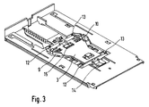
- the cassette holder consists in particular of a base plate 1, a longitudinally displaceable slide 2 and a transversely displaceable sliding element 3.
- the slide 2 can be pushed in against the spring force of a spring 4 in the direction of arrow 5 in the direction of the rear wall 6 and snaps into a storage position, which is shown in FIG , a.
- a storage position which is shown in FIG , a.
- centering elements 7, 8 designed as inclined surfaces onto the back of control wedges 9, 10 which protrude upward on the transversely displaceable sliding element 3.
- the sliding element 3 is thereby pressed into the middle position shown.
- Locking devices covered by a support tongue 11 of the slide 2 are attached to the sliding element 3, on each of which a shaft with pivot pins 12, 13 protrudes. These locking devices 14, 15 with shafts 16, 17 can be seen more clearly in FIGS. 2, 4 and 5.
- the locking devices 14, 15 are in a lower position, while in Figure 4 and Figure 5 and also in Figure 2, the locking devices 14, 15 are shown in an upper position, namely in the locking position.
- Control edges 18, 19 and 20, 21 are provided, which can be seen in Figure 5.
- the control edges 18, 19 serve to pivot the locking devices 14, 15 into the locking position shown there, while the control edges 20, 21 serve to return the locking devices 14, 15 to the lower position, as shown in FIG. 1.
- a side guide 22 is arranged laterally on the base plate 1, which serves as a device for inserting the cassette holder into a container housing.
- the magnetic tape cassette 23 mounted in the slide 2 is pushed so far towards the rear wall 6 that the magnetic tape cassette 23 practically no longer protrudes from the front 24 and a housing closure flap (not shown here) can be closed.
- the bead 24, 25 projecting up and down on the magnetic tape cassette 23 is used for positioning the locking devices.
- the lower bead 25 presses against the control wedge 10 (FIG. 1 and FIG. 3) and thereby pushes the sliding element 3 into the left position shown in FIG. 2. This position is shown from below in FIG. 5, but without a base plate 1.
- the locking devices 14, 15 engage upwards in the coil hubs 26, 27.
- a locking element 28 is arranged on the underside of the slide 2, which in conjunction with a so-called push-push locking device holds the slide 2 in the storage position and releases it when the magnetic tape cassette is tapped again, so that the slide 2 then extends to the removal position.
- the push-push latching device is known per se and is not the subject of the present invention and is therefore not shown in any more detail here.
- the cassette holder has devices with which it can be inserted into and connected to a container housing. These devices include in particular the side guides 22 and the base plate 1.
Landscapes
- Packaging Of Annular Or Rod-Shaped Articles, Wearing Apparel, Cassettes, Or The Like (AREA)
- Automatic Tape Cassette Changers (AREA)
- Registering, Tensioning, Guiding Webs, And Rollers Therefor (AREA)
- Recording Or Reproducing By Magnetic Means (AREA)
Abstract
Description
- Die Erfindung betrifft eine Kassettenhalterung für in Längsrichtung einschiebbare Magnetbandkassetten gemäß Oberbegriff des Anspruchs 1.
- Zur Aufbewahrung von Magnetbandkassetten sind Behälter bekannt, die mehrere Einschuböffnungen für den Längseinschub von Magnetbandkassetten haben. In der eingeschobenen Stellung rastet ein die Magnetbandkassette aufnehmender Schieber ein, so daß die Magnetbandkassette vollständig vom Behälter und einer Verschlußklappe umschlossen ist. Die Entnahme der eingeschobenen Magnetbandkassette erfolgt nun dadurch, daß der Schieber entriegelt wird und eine Feder diesen zusammen mit der darauf abgelegten Magnetbandkassette in eine Entnahmeposition verschiebt. In der Entnahmeposition ragt die Magnetbandkassette aus der Einschuböffnung heraus und kann bequem entnommen werden.
- Ein derartiger Behälter mit mehreren Einschuböffnungen und mehreren Schiebern, die jeweils eine Magnetbandkassette aufnehmen können, ist aus der EP 0 538 585 A2 bekannt. Den einzelnen Einschuböffnungen sind Aufnahmeräume für den Längseinschub von Magnetbandkassetten zugeordnet. In jedem Aufnahmeraum ist auf einer Bodenplatte ein verriegelbarer Schieber gelagert, an dem in die Spulennaben der Magnetbandkassetten eingreifende und in Einschubrichtung fluchtende Arretiereinrichtungen angeordnet sind. Die Arretiereinrichtungen haben den Zweck, daß sich die Spulen nicht unbeabsichtigt drehen können. Eine solche Kassettenhalterung mit Spulenarretierung ist insbesondere bei der Aufbewahrung von Magnetbandkassetten in Kraftfahrzeugen wichtig, da die dort auftretenden Erschütterungen sonst zu unbeabsichtigtem Verdrehen der Spulen führen könnten. Diese bekannte Kassettenhalterung besitzt im Bereich jeder Spulennabe zwei seitlich versetzte Kipphebel als Arretiereinrichtung, wobei je nach Lage der eingelegten Magnetbandkassette der linke oder der rechte Kipphebel in die Spulennabe eingreift. Bei einer eingelegten Magnetbandkassette ohne von außen zugängliche Spulennaben ist keiner der Kipphebel wirksam.
- Der Erfindung liegt die Aufgabe zugrunde, eine Kassettenhalterung für in Längsrichtung einschiebbare Magnetbandkassetten zu schaffen, bei der seitlich verschiebbare Arretiereinrichtungen positionsgenau in die Spulennaben eingreifen können.
- Die Lösung dieser Aufgabe erhält man durch die im Anspruch 1 angegebenen Merkmale. Die Arretiereinrichtungen sind an einem quer verschiebbaren Schiebeelement angebracht, wodurch es möglich ist, daß die Arretiereinrichtung exakt auf die Position der zugehörigen Spulennabe ausgerichtet wird. Die Ausrichtung erfolgt dabei durch den an Magnetbandkassetten beidseitig ausgebildeten Wulst, der je nach Ausrichtung der Magnetbandkassette an linksseitige oder rechtsseitige Steuerkeile des Schiebeelements drückt und dieses zusammen mit den daran angebrachten Arretiereinrichtungen in die erforderliche Position verschiebt. Am längsverschiebbaren Schieber bewirken Steuerkanten, daß die Arretiereinrichtungen bei eingeschobenem Schieber in die Arretierposition verschwenkt werden. Die seitliche Verschiebbarkeit der Arretiereinrichtungen hat insbesondere den Vorteil, daß die Arretiereinrichtungen in ihrer Breite an den Durchmesser der Spulennaben angepaßt sein können und somit an beiden Seitenrändern der Arretiereinrichtungen an den Spulennaben eingreifen.
- Als Betätigungselement für die Arretiereinrichtungen kann eine zu beiden Seiten der Arretiereinrichtungen überstehende Welle vorgesehen sein, an deren beiden freien Enden Schwenkzapfen radial abstehen. Die Schwenkzapfen verändern somit ihre seitliche Position entsprechend der Positionierung des quer verschiebbaren Schiebeelements. Ist das Schiebeelement in einer Mittenposition, so sind die Schwenkzapfen der Arretiereinrichtungen wirkungslos, d. h. daß beim Einschieben einer DAT-Kassette die Arretiereinrichtungen nicht in eine Arretierposition verschwenkt werden. Bei Einschieben einer DAT-Kassette bleibt nämlich das quer verschiebbare Schiebeelement in einer Mittenposition, da an einer solchen DAT-Kassette kein Wulst übersteht, der eine seitliche Verschiebung des Schiebeelements bewirken könnte.
- Das quer verschiebbare Schiebeelement befindet sich vorzugsweise in einer Aussparung der Bodenplatte der Kassettenhalterung und wird von einer am längsverschiebbaren Schieber abstehenden Auflagezunge übergriffen. An der Unterseite der Auflagezunge können sich die Steuerkanten befinden, die je nach Position des quer verschiebbaren Schiebeelements mit den Schwenkzapfen der Arretiereinrichtungen zusammenwirken. Die Auflagezunge hat somit nicht nur die Funktion das Auflageelement für eine eingelegte Magnetbandkassette zu bilden, sondern übernimmt auch die Betätigung der Arretiereinrichtungen.
- Außerdem könnten am längsverschiebbaren Schieber als Schrägflächen ausgebildete Zentrierelemente vorgesehen sein, die in der Endposition des ausgefahrenen Schiebers auf die Steuerkeile des quer verschiebbaren Schiebeelements auftreffen und dieses in eine Mittelposition bringen. Dabei kann die rückwärtige Kante der Steuerkeile für die Ausrichtung des Schiebeelements in Mittelposition dienen, während die vorderen Kanten der Steuerkeile in Verbindung mit den Wulsten der Magnetbandkassetten zur Querverschiebung des Schiebeelements vorgesehen sind.
- Die Kassettenhalterung ist vorzugsweise als Einschub ausgebildet, der in ein Behältergehäuse einsetzbar und mit diesem verbindbar ist. Durch die Ausbildung als Einschub ist es möglich, Behälter mit unterschiedlicher Anzahl von Aufnahmeräumen für Magnetbandkassetten auszubilden, die dann mit einer entsprechenden Anzahl von identischen Einschüben bestückt werden. Bezüglich Anzahl der Aufnahmeräume und bezüglich der äußeren Abmessungen muß lediglich das Behältergehäuse den jeweiligen Anforderungen entsprechend angepaßt sein.
- Die Erfindung wird nachfolgend anhand eines in der Zeichnung dargestellten Ausführungsbeispiels näher erläutert.
- Es zeigen:
- Figur 1 eine Kassettenhalterung mit längsverschiebbarem Schieber und quer verschiebbarem Schiebeelement, wobei sich der Schieber in der ausgefahrenen Entnahmeposition befindet,
- Figur 2 die Kassettenhalterung von Figur 1 mit einer in Aufbewahrungsposition eingeschobenen Magnetbandkassette,
- Figur 3 die Kassettenhalterung von Figur 1 ohne längsverschiebbaren Schieber,
- Figur 4 die Kassettenhalterung von unten in der Position gemäß Figur 2, jedoch ohne Bodenplatte und
- Figur 5 die Kassettenhalterung gemäß Figur 4, jedoch bei um 180° um die Längsachse gedrehter Magnetbandkassette.
- Die in Figur 1 dargestellte Kassettenhalterung ist als ein Einschub ausgebildet, der in Aufnahmeräume eines hier nicht dargestellten Behälters einsetzbar ist. Ein solcher Behälter ist aus der Eingangs genannten EP 0 538 585 A2 bekannt.
- Die Kassettenhalterung besteht insbesondere aus einer Bodenplatte 1, einem längsverschiebbaren Schieber 2 und einem quer verschiebbaren Schiebeelement 3. Der Schieber 2 ist gegen die Federkraft einer Feder 4 in Pfeilrichtung 5 in Richtung Rückwand 6 einschiebbar und rastet in einer Aufbewahrungsposition, die in Figur 2 dargestellt ist, ein. In der in Figur 1 dargestellten Entnahmeposition des Schiebers 2 drückt dieser mit als Schrägflächen ausgebildeten Zentrierelementen 7, 8 auf die Rückseite von Steuerkeilen 9, 10, die am quer verschiebbaren Schiebeelement 3 nach oben abstehen. Das Schiebeelement 3 wird dadurch in die dargestellte Mittelposition gedrückt.
- Am Schiebeelement 3 sind von einer Auflagezunge 11 des Schiebers 2 überdeckte Arretiereinrichtungen angebracht, an denen zu beiden Seiten jeweils eine Welle mit Schwenkzapfen 12, 13 übersteht. In den Figuren 2, 4 und 5 sind diese Arretiereinrichtungen 14, 15 mit Wellen 16, 17 deutlicher ersichtlich. In Figur 3 befinden sich die Arretiereinrichtungen 14, 15 in einer unteren Position, während in Figur 4 und Figur 5 sowie auch in Figur 2 die Arretiereinrichtungen 14, 15 in einer oberen Stellung, nämlich in der Arretierposition dargestellt sind.
- Zur Betätigung der Arretiereinrichtungen 14, 15 sind am Schieber 2 bzw. an dessen Auflagezunge 11 an der Unterseite Steuerkanten 18, 19 sowie 20, 21 vorgesehen, die in Figur 5 ersichtlich sind. Die Steuerkanten 18, 19 dienen dabei dazu, die Arretiereinrichtungen 14, 15 in die dort dargestellte Arretierposition zu verschwenken, während die Steuerkanten 20, 21 für die Rückstellung der Arretiereinrichtungen 14, 15 in die untere Position dienen, wie diese in Figur 1 dargestellt ist.
- In Figur 1 ist weiterhin ersichtlich, daß seitlich an der Bodenplatte 1 eine Seitenführung 22 angeordnet ist, die als Einrichtung zum Einschieben der Kassettenhalterung in ein Behältergehäuse dient.
- Bei der in Figur 2 dargestellten Aufbewahrungsposition befindet sich die im Schieber 2 gelagerte Magnetbandkassette 23 so weit zur Rückwand 6 eingeschoben, daß die Magnetbandkassette 23 an der Vorderseite 24 praktisch nicht mehr übersteht und eine hier nicht dargestellte Gehäuse-Verschlußklappe geschlossen werden kann. Der an der Magnetbandkassette 23 nach oben und unten überstehende Wulst 24, 25 wird zur Positionierung der Arretiereinrichtungen verwendet. Beim Einschieben der Magnetbandkassette 23 drückt der untere Wulst 25 gegen den Steuerkeil 10 (Figur 1 und Figur 3) und drückt dadurch das Schiebeelement 3 in die in Figur 2 dargestellte linke Position. In Figur 5 ist diese Position von unten dargestellt, jedoch ohne Bodenplatte 1.
- Die Arretiereinrichtungen 14, 15 greifen nach oben in die Spulennaben 26, 27 ein.
- Wird die Kassette um ihre Längsachse um 180° verdreht in die Kassettenhalterung eingeschoben, so ergibt sich dadurch die in Figur 4 dargestellte Position, wobei das Schiebeelement 3 von dem Wulst 24 entgegengesetzt zur Darstellung von Figur 5 quer verschoben ist. Beim Einschieben der Magnetbandkassette 23 drückt der Wulst 24 das Schiebeelement 3 an dem Steuerkeil 9 seitlich aus der Mittenposition.
- In Figur 4 und Figur 5 ist an der Unterseite des Schiebers 2 ein Rastelement 28 angeordnet, welches in Verbindung mit einer sogenannten Push-Push-Rasteinrichtung den Schieber 2 in der Aufbewahrungsposition hält und diesen bei erneutem Antippen der Magnetbandkassette wieder freigibt, so daß der Schieber 2 dann in die Entnahmeposition ausfährt. Die Push-Push-Rasteinrichtung ist ansich bekannt und nicht Gegenstand der vorliegenden Erfindung und daher hier auch nicht näher dargestellt.
- Die Kassettenhalterung besitzt Einrichtungen, mit denen sie in ein Behältergehäuse einschiebbar und mit diesem verbindbar ist. Zu diesen Einrichtungen gehören insbesondere die Seitenführungen 22 und die Bodenplatte 1.
Claims (6)
- Kassettenhalterung für in Längsrichtung einschiebbare Magnetbandkassetten, die in die Spulennaben der Magnetbandkassetten eingreifende und in Einschubrichtung fluchtende Arretiereinrichtungen und eine Bodenplatte hat, auf der ein verriegelbarer und mit einer Feder die Magnetbandkassetten in eine Entnahmeposition ausfahrbarer Schieber gelagert ist, wobei in der Bodenplatte ein von der Magnetbandkassette quer zur Einschubrichtung verschiebbares Schiebeelement mit seitlichen Steuerkeilen gelagert ist, und die Schwenkelemente hat, mit denen die Arretiereinrichtungen in die Spulennaben verschwenkbar sind, dadurch gekennzeichnet, daß am quer verschiebbaren Schiebeelement (3) für jede Spulennabe (26, 27) eine Arretiereinrichtung (14, 15) angebracht ist, und daß am längsverschiebbaren Schieber (2) Steuerkanten (18, 19; 20, 21) angeordnet sind, die bei einseitig ausgelenktem Schiebeelement (3) und bei einer Längsverschiebung des Schiebers (2) an einem an einem Betätigungselement der Arretiereinrichtungen (14, 15) abstehenden Schwenkzapfen (12, 13) angreifen und dadurch die Arretiereinrichtungen (14, 15) verschwenken.
- Kassettenhalterung nach Anspruch 1, dadurch gekennzeichnet, daß das Betätigungselement der Arretiereinrichtungen (14, 15) jeweils eine Welle (16, 17) ist, die zu beiden Seiten der zugehörigen Arretiereinrichtung (14, 15) übersteht und an ihren beiden freien Enden radial abstehende Schwenkzapfen (12, 13) hat.
- Kassettenhalterung nach Anspruch 2, dadurch gekennzeichnet, daß das quer verschiebbare Schiebeelement (3) in einer Aussparung der Bodenplatte (1) unter einer am längsverschiebbaren Schieber (2) abstehenden Auflagezunge (11) angeordnet ist, und daß an der Unterseite der Auflagezunge (11) die Steuerkanten (18, 19; 20, 21) angeordnet sind.
- Kassettenhalterung nach einem der vorhergehenden Ansprüche, dadurch gekennzeichnet, daß an dem längsverschiebbaren Schieber (2) als Schrägflächen ausgebildete Zentrierelemente (7, 8) angeordnet sind, die in der Endposition des ausgefahrenen Schiebers (2) auf die Steuerkeile (9, 10) des Schiebeelements (3) auftreffen und dieses in eine Mittelposition verschieben.
- Kassettenhalterung nach einem der vorhergehenden Ansprüche, dadurch gekennzeichnet, daß in der Mittelposition des Schiebeelements (3) die Steuerkanten (18, 19; 20, 21) wirkungslos sind.
- Kassettenhalterung nach einem der vorhergehenden Ansprüche, dadurch gekennzeichnet, daß die Kassettenhalterung ein Einschub ist, der an seiner Bodenplatte (1) Einrichtungen hat, mit denen er in ein Behältergehäuse einschiebbar und mit diesem verbindbar ist.
Applications Claiming Priority (2)
| Application Number | Priority Date | Filing Date | Title |
|---|---|---|---|
| DE4324265A DE4324265A1 (de) | 1993-07-20 | 1993-07-20 | Kassettenhalterung für in Längsrichtung einschiebbare Magnetbandkassetten |
| DE4324265 | 1993-07-20 |
Publications (3)
| Publication Number | Publication Date |
|---|---|
| EP0635831A2 true EP0635831A2 (de) | 1995-01-25 |
| EP0635831A3 EP0635831A3 (en) | 1995-02-15 |
| EP0635831B1 EP0635831B1 (de) | 1998-12-09 |
Family
ID=6493236
Family Applications (1)
| Application Number | Title | Priority Date | Filing Date |
|---|---|---|---|
| EP94107702A Expired - Lifetime EP0635831B1 (de) | 1993-07-20 | 1994-05-18 | Kassettenhalterung für in Längsrichtung einschiebbare Magnetbandkassette |
Country Status (14)
| Country | Link |
|---|---|
| US (1) | US5478144A (de) |
| EP (1) | EP0635831B1 (de) |
| JP (1) | JP2531933B2 (de) |
| KR (2) | KR950004194A (de) |
| AT (1) | ATE174448T1 (de) |
| BR (1) | BR9402860A (de) |
| CZ (1) | CZ285150B6 (de) |
| DE (2) | DE4324265A1 (de) |
| ES (1) | ES2127310T3 (de) |
| HU (1) | HU216766B (de) |
| NO (1) | NO306748B1 (de) |
| PL (1) | PL174318B1 (de) |
| SG (1) | SG42963A1 (de) |
| SK (1) | SK279205B6 (de) |
Families Citing this family (3)
| Publication number | Priority date | Publication date | Assignee | Title |
|---|---|---|---|---|
| DE19609998A1 (de) | 1996-03-14 | 1997-09-18 | Fischer Artur Werke Gmbh | Kassettenhalterung |
| US8049768B2 (en) * | 2006-08-09 | 2011-11-01 | Primera Technology, Inc. | Disc output storage drawer for processor |
| KR102134454B1 (ko) | 2013-06-11 | 2020-07-15 | 삼성전자주식회사 | 컨텐츠 중심 네트워크에서 컨텐츠를 엿듣는 노드의 통신 방법 및 그 노드 |
Family Cites Families (8)
| Publication number | Priority date | Publication date | Assignee | Title |
|---|---|---|---|---|
| US3475031A (en) * | 1961-12-05 | 1969-10-28 | Grundig Emv | Sound reproducing apparatus |
| US3540738A (en) * | 1967-03-15 | 1970-11-17 | Matsushita Electric Industrial Co Ltd | Magnetic tape recorder of magazine type |
| DE2427109C3 (de) * | 1974-06-05 | 1988-02-11 | IDN Inventions and Development of Novelties AG, Chur | Behälter für eine Magnetbandkassette |
| US4216857A (en) * | 1979-04-19 | 1980-08-12 | Huang Lung Fei | Box for reserving cassette or cartridge |
| DE3307451A1 (de) * | 1983-03-03 | 1984-09-06 | Ymos-Metallwerke Wolf & Becker Gmbh & Co, 6053 Obertshausen | Behaelter, insbesondere fuer kassetten |
| DE8808652U1 (de) * | 1988-07-06 | 1989-11-02 | Fischer-Werke Artur Fischer GmbH & Co KG, 7244 Waldachtal | Behälter für Tonbandkassetten |
| DE4039954A1 (de) * | 1990-12-14 | 1992-06-17 | Fischer Artur Werke Gmbh | Behaelter fuer magnetbandkassetten |
| EP0538585B1 (de) * | 1991-10-22 | 1997-01-02 | fischerwerke Artur Fischer GmbH & Co. KG | Behälter für Magnetbandkassetten |
-
1993
- 1993-07-20 DE DE4324265A patent/DE4324265A1/de not_active Withdrawn
-
1994
- 1994-05-18 SG SG1996001494A patent/SG42963A1/en unknown
- 1994-05-18 DE DE59407428T patent/DE59407428D1/de not_active Expired - Fee Related
- 1994-05-18 AT AT94107702T patent/ATE174448T1/de not_active IP Right Cessation
- 1994-05-18 EP EP94107702A patent/EP0635831B1/de not_active Expired - Lifetime
- 1994-05-18 ES ES94107702T patent/ES2127310T3/es not_active Expired - Lifetime
- 1994-06-06 HU HU9401690A patent/HU216766B/hu not_active IP Right Cessation
- 1994-07-08 US US08/273,013 patent/US5478144A/en not_active Expired - Fee Related
- 1994-07-14 SK SK848-94A patent/SK279205B6/sk unknown
- 1994-07-18 JP JP6165409A patent/JP2531933B2/ja not_active Expired - Fee Related
- 1994-07-19 KR KR1019940017345A patent/KR950004194A/ko not_active Withdrawn
- 1994-07-19 NO NO942712A patent/NO306748B1/no not_active IP Right Cessation
- 1994-07-19 PL PL94304344A patent/PL174318B1/pl unknown
- 1994-07-20 BR BR9402860A patent/BR9402860A/pt not_active IP Right Cessation
- 1994-07-20 CZ CZ941745A patent/CZ285150B6/cs not_active IP Right Cessation
-
1998
- 1998-05-06 KR KR2019980007232U patent/KR0138637Y1/ko not_active Expired - Fee Related
Also Published As
| Publication number | Publication date |
|---|---|
| PL174318B1 (pl) | 1998-07-31 |
| KR0138637Y1 (ko) | 1999-04-15 |
| CZ285150B6 (cs) | 1999-05-12 |
| US5478144A (en) | 1995-12-26 |
| EP0635831B1 (de) | 1998-12-09 |
| SG42963A1 (en) | 1997-10-17 |
| NO942712L (no) | 1995-01-23 |
| PL304344A1 (en) | 1995-01-23 |
| BR9402860A (pt) | 1995-04-04 |
| JPH0752991A (ja) | 1995-02-28 |
| JP2531933B2 (ja) | 1996-09-04 |
| SK84894A3 (en) | 1995-03-08 |
| HUT70769A (en) | 1995-11-28 |
| NO942712D0 (no) | 1994-07-19 |
| SK279205B6 (sk) | 1998-08-05 |
| DE4324265A1 (de) | 1995-01-26 |
| KR950004194A (ko) | 1995-02-17 |
| HU9401690D0 (en) | 1994-09-28 |
| DE59407428D1 (de) | 1999-01-21 |
| CZ174594A3 (en) | 1995-02-15 |
| ATE174448T1 (de) | 1998-12-15 |
| EP0635831A3 (en) | 1995-02-15 |
| NO306748B1 (no) | 1999-12-13 |
| ES2127310T3 (es) | 1999-04-16 |
| HU216766B (hu) | 1999-08-30 |
Similar Documents
| Publication | Publication Date | Title |
|---|---|---|
| DE69321805T2 (de) | Magnetbandkassette mit Bandführungsblockverriegelungsmechanismus | |
| DE68918383T2 (de) | Lagerungsgerät für Aufzeichnungsträger. | |
| DE3007948C2 (de) | Kassette für einen bandförmigen Aufzeichnungsträger | |
| DE69207439T2 (de) | Zuführapparat für chipartige elektronische Bauelemente | |
| DE2452647A1 (de) | Aufnahme- und/oder wiedergabegeraet der kassettenbauart | |
| EP0490049B1 (de) | Behälter für Magnetbandkassetten | |
| DE2557519C3 (de) | Bandkassette mit Bandspulen-Bremsvorrichtung | |
| DE2357445B2 (de) | Verriegelungsvorrichtung fuer einen aufzeichnungstraeger-behaelter mit einem diesen behaelter aufnehmenden geraet | |
| DE1586737A1 (de) | Faltschachtel fuer eine Farbband- oder aehnliche Kassette | |
| DE4231574A1 (de) | Ladevorrichtung fuer bandkassetten | |
| DE69923018T2 (de) | Aufzeichnungsträgerkassette mit federgesteuertem Verschluss | |
| EP0134279A1 (de) | Behälter zur Aufbewahrung von Magnetbandkassetten | |
| DE3137889C2 (de) | ||
| DE3546322C2 (de) | ||
| DE60131792T2 (de) | Magnetbandkassette | |
| EP0635831A2 (de) | Kassettenhalterung für in Längsrichtung einschiebbare Magnetbandkassette | |
| DE69325318T2 (de) | Bandkassette | |
| EP0383007A2 (de) | Behälter mit Mangnetbandkassette | |
| DE10220530A1 (de) | Datenspeicherbandkassette mit einem Bandspulenanordnungs-Zentriermittel | |
| DE10023319B4 (de) | Verfahren zum Umspulen von Thermotransferband zum Bebildern von Druckformen | |
| DE4029843A1 (de) | Gehaeuse fuer eine magnetbandkassette | |
| EP0538585B1 (de) | Behälter für Magnetbandkassetten | |
| EP0463320B1 (de) | Behälter für Magnetbandkassetten | |
| DE2019160B2 (de) | Kassette fuer eine mit bandmaterial bewickelte flanschspule | |
| DE10222017B4 (de) | Bandkassette und Bandlaufwerk für breites Magnetaufzeichnungsband |
Legal Events
| Date | Code | Title | Description |
|---|---|---|---|
| PUAI | Public reference made under article 153(3) epc to a published international application that has entered the european phase |
Free format text: ORIGINAL CODE: 0009012 |
|
| PUAL | Search report despatched |
Free format text: ORIGINAL CODE: 0009013 |
|
| AK | Designated contracting states |
Kind code of ref document: A2 Designated state(s): AT BE CH DE DK ES FR GB GR IE IT LI LU NL PT SE |
|
| AK | Designated contracting states |
Kind code of ref document: A3 Designated state(s): AT BE CH DE DK ES FR GB GR IE IT LI LU NL PT SE |
|
| 17P | Request for examination filed |
Effective date: 19950622 |
|
| GRAG | Despatch of communication of intention to grant |
Free format text: ORIGINAL CODE: EPIDOS AGRA |
|
| GRAG | Despatch of communication of intention to grant |
Free format text: ORIGINAL CODE: EPIDOS AGRA |
|
| GRAH | Despatch of communication of intention to grant a patent |
Free format text: ORIGINAL CODE: EPIDOS IGRA |
|
| 17Q | First examination report despatched |
Effective date: 19980519 |
|
| GRAH | Despatch of communication of intention to grant a patent |
Free format text: ORIGINAL CODE: EPIDOS IGRA |
|
| GRAA | (expected) grant |
Free format text: ORIGINAL CODE: 0009210 |
|
| AK | Designated contracting states |
Kind code of ref document: B1 Designated state(s): AT BE CH DE DK ES FR GB GR IE IT LI LU NL PT SE |
|
| PG25 | Lapsed in a contracting state [announced via postgrant information from national office to epo] |
Ref country code: GR Free format text: LAPSE BECAUSE OF NON-PAYMENT OF DUE FEES Effective date: 19981209 |
|
| REF | Corresponds to: |
Ref document number: 174448 Country of ref document: AT Date of ref document: 19981215 Kind code of ref document: T |
|
| REG | Reference to a national code |
Ref country code: CH Ref legal event code: EP |
|
| ET | Fr: translation filed | ||
| REF | Corresponds to: |
Ref document number: 59407428 Country of ref document: DE Date of ref document: 19990121 |
|
| REG | Reference to a national code |
Ref country code: IE Ref legal event code: FG4D Free format text: GERMAN |
|
| ITF | It: translation for a ep patent filed | ||
| PG25 | Lapsed in a contracting state [announced via postgrant information from national office to epo] |
Ref country code: DK Free format text: LAPSE BECAUSE OF FAILURE TO SUBMIT A TRANSLATION OF THE DESCRIPTION OR TO PAY THE FEE WITHIN THE PRESCRIBED TIME-LIMIT Effective date: 19990309 |
|
| PGFP | Annual fee paid to national office [announced via postgrant information from national office to epo] |
Ref country code: PT Payment date: 19990330 Year of fee payment: 6 |
|
| GBT | Gb: translation of ep patent filed (gb section 77(6)(a)/1977) |
Effective date: 19990310 |
|
| REG | Reference to a national code |
Ref country code: ES Ref legal event code: FG2A Ref document number: 2127310 Country of ref document: ES Kind code of ref document: T3 |
|
| PG25 | Lapsed in a contracting state [announced via postgrant information from national office to epo] |
Ref country code: LU Free format text: LAPSE BECAUSE OF NON-PAYMENT OF DUE FEES Effective date: 19990518 |
|
| PGFP | Annual fee paid to national office [announced via postgrant information from national office to epo] |
Ref country code: AT Payment date: 19990518 Year of fee payment: 6 |
|
| PGFP | Annual fee paid to national office [announced via postgrant information from national office to epo] |
Ref country code: ES Payment date: 19990526 Year of fee payment: 6 |
|
| PG25 | Lapsed in a contracting state [announced via postgrant information from national office to epo] |
Ref country code: LI Free format text: LAPSE BECAUSE OF NON-PAYMENT OF DUE FEES Effective date: 19990531 Ref country code: CH Free format text: LAPSE BECAUSE OF NON-PAYMENT OF DUE FEES Effective date: 19990531 Ref country code: BE Free format text: LAPSE BECAUSE OF NON-PAYMENT OF DUE FEES Effective date: 19990531 |
|
| PGFP | Annual fee paid to national office [announced via postgrant information from national office to epo] |
Ref country code: NL Payment date: 19990531 Year of fee payment: 6 |
|
| REG | Reference to a national code |
Ref country code: PT Ref legal event code: SC4A Free format text: AVAILABILITY OF NATIONAL TRANSLATION Effective date: 19990301 |
|
| PG25 | Lapsed in a contracting state [announced via postgrant information from national office to epo] |
Ref country code: IE Free format text: LAPSE BECAUSE OF NON-PAYMENT OF DUE FEES Effective date: 19990820 |
|
| REG | Reference to a national code |
Ref country code: IE Ref legal event code: FD4D |
|
| PLBE | No opposition filed within time limit |
Free format text: ORIGINAL CODE: 0009261 |
|
| STAA | Information on the status of an ep patent application or granted ep patent |
Free format text: STATUS: NO OPPOSITION FILED WITHIN TIME LIMIT |
|
| BERE | Be: lapsed |
Owner name: FISCHERWERKE ARTUR FISCHER G.M.B.H. & CO. K.G. Effective date: 19990531 |
|
| 26N | No opposition filed | ||
| REG | Reference to a national code |
Ref country code: CH Ref legal event code: PL |
|
| PG25 | Lapsed in a contracting state [announced via postgrant information from national office to epo] |
Ref country code: AT Free format text: LAPSE BECAUSE OF NON-PAYMENT OF DUE FEES Effective date: 20000518 |
|
| PG25 | Lapsed in a contracting state [announced via postgrant information from national office to epo] |
Ref country code: ES Free format text: THE PATENT HAS BEEN ANNULLED BY A DECISION OF A NATIONAL AUTHORITY Effective date: 20000519 |
|
| PG25 | Lapsed in a contracting state [announced via postgrant information from national office to epo] |
Ref country code: PT Free format text: LAPSE BECAUSE OF NON-PAYMENT OF DUE FEES Effective date: 20001130 |
|
| PG25 | Lapsed in a contracting state [announced via postgrant information from national office to epo] |
Ref country code: NL Free format text: LAPSE BECAUSE OF NON-PAYMENT OF DUE FEES Effective date: 20001201 |
|
| NLV4 | Nl: lapsed or anulled due to non-payment of the annual fee |
Effective date: 20001201 |
|
| REG | Reference to a national code |
Ref country code: PT Ref legal event code: MM4A Free format text: LAPSE DUE TO NON-PAYMENT OF FEES Effective date: 20001130 |
|
| REG | Reference to a national code |
Ref country code: GB Ref legal event code: IF02 |
|
| REG | Reference to a national code |
Ref country code: ES Ref legal event code: FD2A Effective date: 20020204 |
|
| PGFP | Annual fee paid to national office [announced via postgrant information from national office to epo] |
Ref country code: GB Payment date: 20030514 Year of fee payment: 10 |
|
| PGFP | Annual fee paid to national office [announced via postgrant information from national office to epo] |
Ref country code: SE Payment date: 20030515 Year of fee payment: 10 |
|
| PGFP | Annual fee paid to national office [announced via postgrant information from national office to epo] |
Ref country code: FR Payment date: 20030527 Year of fee payment: 10 |
|
| PGFP | Annual fee paid to national office [announced via postgrant information from national office to epo] |
Ref country code: DE Payment date: 20040312 Year of fee payment: 11 |
|
| PG25 | Lapsed in a contracting state [announced via postgrant information from national office to epo] |
Ref country code: GB Free format text: LAPSE BECAUSE OF NON-PAYMENT OF DUE FEES Effective date: 20040518 |
|
| PG25 | Lapsed in a contracting state [announced via postgrant information from national office to epo] |
Ref country code: SE Free format text: LAPSE BECAUSE OF NON-PAYMENT OF DUE FEES Effective date: 20040519 |
|
| EUG | Se: european patent has lapsed | ||
| GBPC | Gb: european patent ceased through non-payment of renewal fee |
Effective date: 20040518 |
|
| PG25 | Lapsed in a contracting state [announced via postgrant information from national office to epo] |
Ref country code: FR Free format text: LAPSE BECAUSE OF NON-PAYMENT OF DUE FEES Effective date: 20050131 |
|
| REG | Reference to a national code |
Ref country code: FR Ref legal event code: ST |
|
| PG25 | Lapsed in a contracting state [announced via postgrant information from national office to epo] |
Ref country code: IT Free format text: LAPSE BECAUSE OF NON-PAYMENT OF DUE FEES;WARNING: LAPSES OF ITALIAN PATENTS WITH EFFECTIVE DATE BEFORE 2007 MAY HAVE OCCURRED AT ANY TIME BEFORE 2007. THE CORRECT EFFECTIVE DATE MAY BE DIFFERENT FROM THE ONE RECORDED. Effective date: 20050518 |
|
| PG25 | Lapsed in a contracting state [announced via postgrant information from national office to epo] |
Ref country code: DE Free format text: LAPSE BECAUSE OF NON-PAYMENT OF DUE FEES Effective date: 20051201 |