EP0635967A2 - Appareil de synthèse d'image - Google Patents
Appareil de synthèse d'image Download PDFInfo
- Publication number
- EP0635967A2 EP0635967A2 EP94111475A EP94111475A EP0635967A2 EP 0635967 A2 EP0635967 A2 EP 0635967A2 EP 94111475 A EP94111475 A EP 94111475A EP 94111475 A EP94111475 A EP 94111475A EP 0635967 A2 EP0635967 A2 EP 0635967A2
- Authority
- EP
- European Patent Office
- Prior art keywords
- image
- mode
- input
- setting
- print data
- Prior art date
- Legal status (The legal status is an assumption and is not a legal conclusion. Google has not performed a legal analysis and makes no representation as to the accuracy of the status listed.)
- Granted
Links
- 230000002194 synthesizing effect Effects 0.000 title claims abstract description 32
- 238000003786 synthesis reaction Methods 0.000 claims abstract description 83
- 230000015572 biosynthetic process Effects 0.000 claims abstract description 82
- 238000000034 method Methods 0.000 claims description 19
- 230000008569 process Effects 0.000 claims description 16
- 238000012545 processing Methods 0.000 claims description 16
- 230000005540 biological transmission Effects 0.000 claims description 12
- 230000004044 response Effects 0.000 claims description 3
- 230000006870 function Effects 0.000 description 15
- 238000009966 trimming Methods 0.000 description 10
- 230000000994 depressogenic effect Effects 0.000 description 4
- 230000000694 effects Effects 0.000 description 4
- 238000010586 diagram Methods 0.000 description 3
- 238000004891 communication Methods 0.000 description 2
- 239000011521 glass Substances 0.000 description 2
- 230000001678 irradiating effect Effects 0.000 description 2
- 238000012546 transfer Methods 0.000 description 2
- 230000007704 transition Effects 0.000 description 2
- 230000004075 alteration Effects 0.000 description 1
- 238000006243 chemical reaction Methods 0.000 description 1
- 238000001514 detection method Methods 0.000 description 1
- 238000012986 modification Methods 0.000 description 1
- 230000004048 modification Effects 0.000 description 1
- 230000003287 optical effect Effects 0.000 description 1
Images


Classifications
-
- H—ELECTRICITY
- H04—ELECTRIC COMMUNICATION TECHNIQUE
- H04N—PICTORIAL COMMUNICATION, e.g. TELEVISION
- H04N1/00—Scanning, transmission or reproduction of documents or the like, e.g. facsimile transmission; Details thereof
- H04N1/387—Composing, repositioning or otherwise geometrically modifying originals
- H04N1/3872—Repositioning or masking
- H04N1/3873—Repositioning or masking defined only by a limited number of coordinate points or parameters, e.g. corners, centre; for trimming
-
- H—ELECTRICITY
- H04—ELECTRIC COMMUNICATION TECHNIQUE
- H04N—PICTORIAL COMMUNICATION, e.g. TELEVISION
- H04N1/00—Scanning, transmission or reproduction of documents or the like, e.g. facsimile transmission; Details thereof
Definitions
- the present invention relates to an image synthesizing apparatus for synthesizing an original image and an externally entered image.
- Such apparatus is provided with a memory for storing image data, for the purpose of synthesizing an original image with an externally entered (input) image, and the image synthesis is conducted in such memory.
- the image scanned in the scanner is exclusively used for synthesis with the image from the computer while the image synthesizing mode is selected. Consequently the scanner unit cannot be utilized for other functions such as copying or facsimile transmission but is entirely occupied by the specified function, so that the utilization of the apparatus for other functions is limited.
- the operator For releasing the scanner unit from the occupied state for image synthesis, the operator is required to intentionally effect a cancelling operation for said image synthesis mode, so that the burden for the operator becomes larger.
- An object of the present invention is to provide an image synthesizing apparatus not associated with the above-mentioned drawbacks.
- Still another object of the present invention is to provide an image synthesizing apparatus capable of automatically cancelling the synthesizing mode in case the information to be synthesized is not released from the computer, thereby enabling operations in other functions and reducing the wasted inoperable time.
- Fig. 1 is a block diagram showing the configuration of a multifunctional image processing apparatus in which the present invention is applicable.
- an image input device (reader unit) 1 for reading an original and converting the image thereof into image data
- an image output device (printer unit) 2 containing plural recording sheet cassettes and adapted, in response to a printing command, to release the image data as a visible image on a recording sheet
- an external device 3 electrically connected with said reader unit 1 and adapted to effect various functions.
- the external device 3 is provided with a facsimile unit 4, a file unit 5, an external memory device 6 connected to said file unit 5, a computer interface unit 7 for connection with a computer and a LAN, a formatter unit 9 for converting information from the computer into image information, an image memory unit 9 for storing the information from said reader unit 1 and temporarily storing the information transmitted from the computer, and a core unit 10 for controlling the functions of the above-mentioned units.
- a reader control unit CONT1 and a printer control unit CONT2 capable of communication with the core unit 10 of the external device 3 and respectively provided with a CPU, a ROM, a RAM etc.
- an editor 11 is connected to the reader unit 1, and is used for area designation etc.
- Fig. 2 is a cross-sectional view showing the configuration of the reader unit 1 and the printer unit 2 shown in Fig. 1, and the structure and function of these units will be explained in the following.
- Originals stacked on an original feeder 101 are transported, one by one, onto an original supporting glass 102.
- a lamp 103 is turned on in the scanner unit, and a scanner unit 104 is moved to illuminate the original.
- the light reflected from the original is guided through mirrors 105, 106, 107 and a lens 108 and is focused on a CCD image sensor 109.
- the light reflected from the original and focused on the CCD 109 is subjected to photoelectric conversion therein, and the electrical signal released therefrom is subjected, in an image processing unit 110, to various image processings.
- the image processing unit 110 is provided with a selector guiding thus processed image signal either to the printer unit 2 or to the external device 3. Said selector also serves to select either the signal from the reader unit 1 or the signal from the external device 3 for supply to the printer unit 2.
- the electrical signal supplied from the selector of the image processing unit 110 to the printer unit 2 is converted, in an exposure control unit 201, into a modulated optical signal for irradiating a photosensitive member 202.
- a latent image, formed by said irradiating light on the photosensitive member 202 is developed with toner in a developing unit 203.
- a recording sheet is transported from a sheet stacker unit 204 or 205, in synchronization with the front end of said latent image, and thus developed image is transferred onto the recording sheet in a transfer unit 206.
- the transferred image is fixed, in a fixing unit 207, onto the recording sheet, which is then discharged from the apparatus through a discharge unit 208.
- the sheets from the discharge unit 208 is discharged, into bins of a sorter 220 when the sorting function thereof is selected. On the other hand, when said sorting function is not selected, the sheets are discharged into the uppermost bin of the sorter 220.
- the recording sheet subjected to the image fixation in the fixing unit 207, is transported to the discharge unit 208, and is then transported in the opposite direction through a switching member 209, to a re-feeding stacker 210.
- the original image is read in the same manner as explained above but the recording sheet is supplied from the re-feeding stacker 210, so that two original images can be recorded on both faces of a same recording sheet.
- the external device 3 is connected, as shown in Fig. 1, with a cable to the reader unit 1, and the core unit 10 in said external device 3 controls various signals and various functions.
- the external unit 3 is provided therein with a facsimile unit 4 for facsimile transmission and reception, a file unit 5 for converting original information into electrical signals and storing said signals on a magnetooptical disk, a formatter unit 8 for developing the code information from a computer into image information, a computer interface unit 7 for interfacing with a LAN and a computer, an image memory unit 9 for storing the information from the reader unit 1 or temporarily storing the information from the computer, and a core unit 10 for controlling the above-mentioned units.
- Fig. 3 is a plan view showing an example of the operation panel provided on the reader unit 1 shown in Fig. 1.
- a display unit 301 displays the states of operation and messages.
- the surface of said display unit 301 is composed of a touch panel, serving as selection keys when touched with a finger.
- Numeral keys 302 are used for entering numbers.
- a start key 303 initiates the function of copying or facsimile.
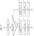
- initialization (1) After the start of power supply, there is executed initialization (1). At the right-hand end of the display unit 301 of the operation panel there are displayed operation mode selection keys, and an operation mode is selected when the panel on a displayed selection key is touched. Then there is discriminated whether the selected mode is the copy mode (2), and, if the copy mode is selected, the sequence proceeds to a step (1) shown in Fig. 5.
- step (2) if the step (2) identifies that the copy mode is not selected, there is discriminated whether the facsimile transmission mode is selected (3), and, if so, the sequence proceeds to a step (1) shown in Fig. 6.
- step (3) identifies that the facsimile transmission mode is not selected, there is discriminated whether the file mode is selected (4), and, if selected, the sequence proceeds to a step (1) in Fig. 7.
- step (4) identifies that the file mode is not selected, there is discriminated whether the input mode from the computer interface unit 7 is selected as the printer mode (5), and, if selected, the sequence proceeds to a step (1) in Fig. 8.
- step (5) identifies that the input mode is not selected, there is discriminated whether the image synthesis mode is selected as the printer mode (6), and, if selected, the sequence proceeds to a step (16) in Fig. 10.
- the image synthesis mode effects synthesis of an image read in the reader unit 1 with an image released from the formatter unit 8, as will be explained later in more details.
- step (6) identifies that the image synthesis mode is not selected, there is discriminated whether the facsimile reception mode is selected (7), and, if selected, the sequence proceeds to a step (1) in Fig. 9.
- step (7) identifies that the facsimile reception mode is not selected, the sequence returns to the step (2) and repeats the above-mentioned steps.
- step (2) in Fig. 4 identifies that the copy mode is selected
- the flow shown in Fig. 5 is initiated.
- initialization for the copying operation (1) There is executed initialization for the copying operation (1).
- copying conditions are set by reading the key information entered from the operation panel (2), and the actuation of the start key 303 is awaited (3).
- start key 303 is depressed, the original is read in the reader unit 1 (4), and the printing operation is conducted in the printer unit 2 as explained in the foregoing (5).
- the sequence returns to the step (1) shown in Fig. 4, for the purpose of initialization.
- step (3) in Fig. 4 identifies that the facsimile transmission mode is selected
- the flow shown in Fig. 6 is initiated. At first there is executed initialization for the facsimile transmission (1). Then facsimile transmission conditions are set by reading the key information entered from the operation panel (2), and the actuation of the start key 303 is awaited (3).
- the original is read in the reader unit 1 (4), and the obtained image data are supplied to the facsimile unit 4, which effects the facsimile transmission according to the set format and a predetermined protocol (5). After the transmission is completed, the sequence returns to the step (1) in Fig. 4.
- the flow shown in Fig. 7 is initiated. At first there is executed initialization for the file operation (1). On the operation panel there are displayed mode selection keys for file recording and for file search, and the key input by the operator is awaited (2). If the recording key is selected, there is effected setting of the recording conditions (3). Then the original is read in the reader unit 1 (4), the obtained data are transferred to the file unit 5 and are recorded in the external memory device 6 thereof (5).
- the search conditions are set (6), then the file is searched from the external memory device 6 (7), and the result of search is released (8). After the completion of file recording or file search, the sequence returns to the step (1) in Fig. 4 for initialization.
- step (5) in Fig. 4 identifies the entry of command and data from the outside
- the flow shown in Fig. 8 is initiated.
- command is received in the computer interface unit 7 (1), then the data are supplied through the core unit 10 to the formatter unit 8 and are converted into image information for printing (2).
- the printer unit 2 is in operation (3), and, if not, the image information is supplied to the printer unit 2 and printed therein (4). Thereafter the sequence returns to the step (1) in Fig. 4.
- the image information is stored in the image memory unit 9 (5). Then the sequence returns to the step (3), and the stored data are read and printed in the printer unit 2 when the printer unit 2 is not in operation (3, 4). Thereafter the sequence returns to the step (1) in Fig. 4.
- step (5) in Fig. 4 identifies that command and data are not received from the outside, there is discriminated whether the operation in the synthesis mode is in progress (6), and, if in progress, the flow shown in Fig. 10 is initiated. If the operation in the synthesis mode is not in progress, there is discriminated whether the facimile reception is in progress (7), and, if not, the sequence returns to the step (2) shown in Fig. 4. If it is identified that the facsimile reception is in progress, the flow shown in Fig. 9 is initiated. At first the facsimile reception is conducted by the facsimile unit 4 (1), then there is discriminated whether the printer unit 2 is in operation (2), and, if not, the received data are supplied to the printer unit 2 and printed therein (3).
- step (2) if the step (2) identifies that the printer unit 2 is in operation, the received data are stored in the rigid disk of the facsimile unit 4 (4), and are printed in the printer unit 2 when it is not in operation (2, 3). After the completion of the printing operation, the sequence returns to the step (1) in Fig. 4 for initialization.
- the above-explained modes are executed according to the mode selection by the selection keys 301 of the operation panel, reception of information by the facsimile unit 4, or detection of the external command by the computer interface unit 7.
- the core unit 10 controls the priority setting and the parallel execution of the operations of these functions.
- the scanner synthesis operation for synthesizing the image information, converted in the formatter unit 8, with the original image read in the reader unit 1, according to synthesis area data indicated by the keys 301, 302 of the operation unit shown in Fig. 3 or by the deiter 11.
- Fig. 10 is a flow chart showing an example of the image synthesizing sequence in the multifunctional image processing apparatus of the present invention, wherein parenthesized numbers (1) to (18) indicate process steps.
- the sequence normally proceeds to the printing sequence shown in Fig. 8, but there is discriminated whether the synthesis mode is selected in the operation unit (1), and, if not, the sequence shown in Fig. 8 is initiated, but, if selected, the sequence shown in Fig. 10 is initiated.
- the synthesis mode is initiated, the use of the reader unit 1 in the copy mode, facsimile transmission mode or file recording mode is inhibited (2). This is to prevent that the original to be used in the synthesis mode is replaced by an original for another mode, while the transmission of the image to be synthesized from the formatter unit 8 is awaited.
- the formatter unit 8 Upon receiving a print command from the computer (3), the formatter unit 8 terminates the time measuring operation of a timer 10d (4), and converts the command and data into image information, representing characters etc. in the same manner as in the ordinary command converting operation (5). Then, if the printer unit is not in operation when the converted image information becomes ready for output (6), the data output to the printer unit is initiated. At this point, the reader control unit discriminates whether the original image reading is in the feeder mode (7). This discrimination is achieved by an unrepresented sensor provided in the original feeder 101 shown in Fig. 1, depending on whether an original is present on the original stacker.
- said original is transported to the exposure position, prior to the reception of the image information from the formatter unit 8 (8). Then a recording sheet is fed from a suitable stacker (cassette) 204, 205 (9) to the transfer position 206.
- the scanner unit 104 is so moved that a latent image synthesized from the image information from the formatter unit 8 and from the original image is formed with a suitable timing on the photosensitive member 202 (10), and the original image data are read with the CCD 109.
- the original image thus read and the image data released from the formatter unit 8 are selectively supplied, according to data indicating the designated synthesis areas, in the external switching circuit to be explained later, to the exposure control unit 201 and are printed by a known electrophotographic process (11).
- the printing operation will not be explained further as it is similar to that in the above-explained various modes.
- FIG. 11 there are shown an image data signal 1101 from an external equipment; an image data signal 1102 from the above-mentioned image processing unit 110; a selector 1100 for selecting either the image signal 1101 or 1102; an image data signal 1103 selected by the selector 1100 and supplied to the exposure control unit 201 for forming the latent image; an area judging circuit 1105 for the main scanning direction and an area judging circuit 1106 for the sub scanning direction, for judging inside and outside of the area in respective directions; and an area judging circuit 1104 for effecting final area judgment, based on the results of judgment in the above-mentioned directions and transmitting the result of final judgment to the selector 1100 for selecting the signals accordingly.
- a CPU 10a for effecting various image processings by controlling the access to the units 4 - 9 shown in Fig. 1 and the communication with the reader unit 1 and the printer unit 2, according to a control program stored in a ROM 10b; a RAM 10c for storing the time for cancelling the image synthesis mode instructed by the operation unit 20, the number of synthesized images (number of pages), the measured time etc.; and a timer 10d for effecting a time measuring process depending on the result of discrimination whether the number of pages of the synthesized images does not exceed a designated number of pages.
- a first original to be synthesized is fed from the stacker of the original feeder 101 (11), and said original feeder 101 discriminates, by means of the aforementioned sensor, whether a next original is present (12). If the next original is absent, the sequence is executed once after the printing of the synthesized image, but, in case of presence of the next original, the original is changed (8) and a next recording sheet is fed.
- the same external image data can be synthesized with each of the images of plural originals, by repeating the above-explained sequence.
- the formatter unit 8 can send same image data to the external switching circuit any number of times, in synchronization with the timing of original reading of the reader unit 1.
- the main scanning area judging circuit 1105 receives a pixel clock signal 1107 in the main scanning direction and a main scanning reference signal 1108 indicating the reference position of each main scanning line, and judges, for each main scanning line, whether the current scanning position is inside or outside the designated synthesis area.
- the sub scanning area judging circuit 1106 receives a line clock signal 1110 in the sub scanning direction and a sub scanning reference signal 1109 indicating the reference position in the sub scanning direction, and discriminates whether the current scanning position is inside or outside the designated synthesis area.
- the number of pages of the external image data to be synthesized can be designated, for example, by the keys of the operation unit 20 shown in Fig. 1. After the completion of synthesis of same external image data with plural originals, there is discriminated whether a page number is designated for cancelling the synthesis mode (13).
- step (14) if the step (14) identifies that the designated number of pages has not been reached, there is initiated the counting operation of the designated time by the timer 10d (15).
- step (16) is also executed in case the step (5) in Fig. 4 identifies the absence of the external input or in case the step (6) in Fig. 4 identifies the selection of the synthesis mode.
- step (16) identifies that the designated time has elapsed, the synthesis mode is automatically cancelled (17), then the request for use of the reader unit 1 is permitted (18), and the sequence returns to the step (1) in Fig. 4.
- the image synthesis mode is cancelled, based on the number of pages, designated from the operation unit, of the print data to be subjected to scanner synthesis, but it is also possible to designate the number of pages of the originals to be read by the reader unit and to cancel the image synthesis mode, based on said number of pages of the originals.
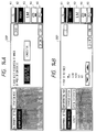
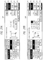
- Figs. 12A to 14B are views showing the transitions of the displayed image of the display unit 301 in said scanner synthesis mode.
- the operation unit 301 is composed of a display DSP with a touch panel including keys K1 - K5, and the instruction for operation can be entered by touching one of the key areas displayed on said display DSP.
- a key area "OFF LINE” is touched as shown in Fig. 12A, whereby the display of said area is inverted and the printer unit is shifted to the off-line state.
- the display DSP is switched to a state shown in Fig. 12B, wherein the display of the key area "SCANNER SYNTHESIS” is inverted.
- an area, in which the image is to be fitted is designated by two diagonal points on the editor 11, by means of a pen, or by touching a key area "TEN KEY INPUT" to shift the display DSP to a state shown in Fig. 12C and by entering the numbers of coordinates by means of the numeral keys 302 of the operation unit.
- the entered two points are displayed as shown in Fig. 12D. If a key area "POINT CLEAR" is depressed in this state, the display DSP is switched to a state shown in Fig. 12B, whereby the two points designating the area for image fitting are entered again. In the present embodiment, the point clearing operaiton is conducted one by one among the designated two points.
- the display DSP is shifted to a state shown in Fig. 13B for designating whether the original image read by the scanner is to be synthesized either inside or outside of the image fitting area designated above.
- the outside is selected whereby "OUTSIDE" area is inverted in display.
- a key area "CANCEL” is touched in the state shown in Fig. 13B, the display DSP is shifted to a state shown in Fig. 13A, in which the alteration of the area is enabled.
- the display is shifted to a state shown in Fig. 12B for re-designation of the area.
- the key area "CANCEL” is touched in a state shown in Fig. 13A, the display DSP is shifted to a state shown in Fig. 12A.
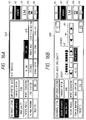
- Fig. 15 shows an example of the display of a stand-by state for scanner synthesis.
- Figs. 16A and 16B show an example of the option setting display in the scanner synthesis mode, relating particularly to image quality setting operations.
- a display state shown in Fig. 16A in which a key area "SCANNER SYNTHESIS” is inverted in display, the depression of a key area “IMAGE QUALITY” shifts the display to a state shown in Fig. 16B to enable designation of density (hi-fi/character emphasis), sharpness etc.. It is thus rendered possible to regulate the print density or to emphasize the image contrast, according to the kind or original, such as a character original or a photograph original. If a key area "OK” or "C” is touched in a display state shown in Fig. 16B, the display DSP is switched to a state shown in Fig. 16A, whereby the re-setting of the conditions is rendered possible.
- Figs. 17A and 17B show an example of the option setting display in the scanner synthesis mode, relating particularly to image creation setting operations.
- a display state shown in Fig. 17A in which a key area "SCANNER SYNTHESIS” is inverted in display, the depression of a key area “IMAGE CREATE” shifts the display DSP to a state shown in Fig. 17B, to enable various image creating processes, as indicated by key areas "OUTLINE", “NET”, “SHADOW” and "NEG/POS REVERSAL". If a key area "OK” or “C” is touched in a display state shown in Fig. 17A, the display DSP is switched to a state shown in Fig. 17A, whereby the re-setting of the conditions is rendered possible.
- Figs. 18A to 19B show an example of the option setting display in the scanner synthesis mode, relating particularly to trimming/movement setting operations.
- an area, in which the image is to be fitted is designated by two diagonal points on the editor 11, by means of a pen, or by touching a key area "TEN KEY INPUT" to shift the display DSP to a state shown in Fig. 18C and by entering the coordinate values by means of the numeral keys 302 of the operation unit.
- the entered two points are displayed as shown in Fig. 18D. If a key area "POINT CLEAR" is depressed in this state, the display DSP is switched to a state shown in Fig. 18B, whereby the two points designating the area for image fitting are entered again. In the present embodiment, the point clearing operation is conducted one by one among the designated two points.
- a key area "OK” is touched in the state shown in Fig. 18D
- the display DSP is shifted to a state shown in Fig. 19B.
- a key area "TRIMMING/MOVEMENT” is touched, the display DSP is switched to a state shown in Fig. 19A, in which the designated trimming or movement is graphically displayed. If the key area "OK” is touched in this state, the display DSP is switched again to the state shown in Fig. 19B, and the trimming/movement setting operation is thus completed.
- a key area "AREA CLEAR" is touched in a state shown in Fig. 19A
- the display DSP is switched to a state shown in Fig. 18B, whereby the area designation for trimming/movement is enabled again.
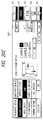
- Figs. 20A to 21B show an example of the option setting display in the scanner synthesis mode, relating particularly to zoom setting operations.
- the image magnification is determined, based on the size of the original image and that of the designated area of synthesis, so as to select a maximum magnification capable of fitting the original image in the entire area of synthesis.
- the image magnification is determined, based on the size of the original and that of the recording sheet, so as to select a maximum magnification capable of fitting the original image in the entire recording sheet.
- the magnification is determined according to the size of the trimming area, instead of the original size.
Landscapes
- Engineering & Computer Science (AREA)
- Multimedia (AREA)
- Signal Processing (AREA)
- Editing Of Facsimile Originals (AREA)
- Facsimiles In General (AREA)
- Image Processing (AREA)
- Processing Or Creating Images (AREA)
Applications Claiming Priority (3)
| Application Number | Priority Date | Filing Date | Title |
|---|---|---|---|
| JP20260793A JP3337768B2 (ja) | 1993-07-23 | 1993-07-23 | 複合画像形成装置および複合画像形成装置の制御方法 |
| JP202607/93 | 1993-07-23 | ||
| JP20260793 | 1993-07-23 |
Publications (3)
| Publication Number | Publication Date |
|---|---|
| EP0635967A2 true EP0635967A2 (fr) | 1995-01-25 |
| EP0635967A3 EP0635967A3 (fr) | 1996-05-01 |
| EP0635967B1 EP0635967B1 (fr) | 1999-11-03 |
Family
ID=16460226
Family Applications (1)
| Application Number | Title | Priority Date | Filing Date |
|---|---|---|---|
| EP94111475A Expired - Lifetime EP0635967B1 (fr) | 1993-07-23 | 1994-07-22 | Appareil de synthèse d'image |
Country Status (6)
| Country | Link |
|---|---|
| US (1) | US5732161A (fr) |
| EP (1) | EP0635967B1 (fr) |
| JP (1) | JP3337768B2 (fr) |
| KR (1) | KR0134739B1 (fr) |
| CN (1) | CN1110418A (fr) |
| DE (1) | DE69421460T2 (fr) |
Cited By (1)
| Publication number | Priority date | Publication date | Assignee | Title |
|---|---|---|---|---|
| EP0833210A3 (fr) * | 1996-09-30 | 1998-12-09 | Kabushiki Kaisha Toshiba | Appareil de formation d'images pour stocker d'une image de document dans un mémoire en cours d'une opération d'alimentation de document et procédé associé |
Families Citing this family (13)
| Publication number | Priority date | Publication date | Assignee | Title |
|---|---|---|---|---|
| TW293981B (fr) * | 1995-07-21 | 1996-12-21 | Philips Electronics Nv | |
| US6229620B1 (en) * | 1995-08-29 | 2001-05-08 | Canon Kabushiki Kaisha | Image processing apparatus and method thereof |
| JP3745136B2 (ja) * | 1997-12-15 | 2006-02-15 | キヤノン株式会社 | 印刷装置及び情報処理装置及びそれらの制御方法 |
| US6513073B1 (en) * | 1998-01-30 | 2003-01-28 | Brother Kogyo Kabushiki Kaisha | Data output method and apparatus having stored parameters |
| US6667814B1 (en) | 1999-09-15 | 2003-12-23 | Lexmark International, Inc. | Automatic up image printing |
| JP2001177764A (ja) * | 1999-12-17 | 2001-06-29 | Canon Inc | 画像処理装置、画像処理方法および記憶媒体 |
| US7262778B1 (en) * | 2000-02-11 | 2007-08-28 | Sony Corporation | Automatic color adjustment of a template design |
| US7136528B2 (en) * | 2000-02-11 | 2006-11-14 | Sony Corporation | System and method for editing digital images |
| US6993719B1 (en) | 2000-02-11 | 2006-01-31 | Sony Corporation | System and method for animated character photo-editing interface and cross-platform education icon |
| US20020012424A1 (en) * | 2000-07-18 | 2002-01-31 | Tatsuya Nishio | Communication apparatus |
| US6654507B2 (en) * | 2000-12-14 | 2003-11-25 | Eastman Kodak Company | Automatically producing an image of a portion of a photographic image |
| US7454707B2 (en) * | 2002-09-30 | 2008-11-18 | Canon Kabushiki Kaisha | Image editing method, image editing apparatus, program for implementing image editing method, and recording medium recording program |
| US7433091B2 (en) * | 2002-11-28 | 2008-10-07 | Canon Kabushiki Kaisha | Image forming and reading apparatus |
Family Cites Families (14)
| Publication number | Priority date | Publication date | Assignee | Title |
|---|---|---|---|---|
| JPS5487011A (en) * | 1977-12-22 | 1979-07-11 | Ricoh Co Ltd | Telautogram information transmitting device |
| JPS57150062A (en) * | 1981-03-12 | 1982-09-16 | Fuji Xerox Co Ltd | Processing of papers |
| GB2101838B (en) * | 1981-04-20 | 1986-03-05 | Canon Kk | Image processing method and apparatus therefor |
| JPH0677173B2 (ja) * | 1982-11-10 | 1994-09-28 | キヤノン株式会社 | 像形成装置 |
| US4727435A (en) * | 1984-09-21 | 1988-02-23 | Canon Kabushiki Kaisha | Image information processing system |
| US4897734A (en) * | 1985-10-28 | 1990-01-30 | Canon Kabushiki Kaisha | Image processing apparatus |
| JPS6319952A (ja) * | 1986-07-12 | 1988-01-27 | Ricoh Co Ltd | フアクシミリ装置 |
| JP2740181B2 (ja) * | 1987-05-09 | 1998-04-15 | 株式会社リコー | 複写装置 |
| US5204759A (en) * | 1987-10-16 | 1993-04-20 | Canon Kabushiki Kaisha | Image processing apparatus |
| EP0312301B1 (fr) * | 1987-10-16 | 1994-04-27 | Canon Kabushiki Kaisha | Appareil de production d'images |
| DE68928557T2 (de) * | 1988-11-14 | 1998-05-14 | Canon Kk | Bildverarbeitungsgerät und -methode |
| JP3039658B2 (ja) * | 1989-05-10 | 2000-05-08 | キヤノン株式会社 | 画像処理装置及び方法 |
| US5038218A (en) * | 1990-10-10 | 1991-08-06 | Fuji Xerox Co., Ltd. | Image processing assembly with conversion and rotation of input image data or predetermined data to match data resolution and orientation |
| US5396345A (en) * | 1991-12-19 | 1995-03-07 | Ricoh Company, Ltd. | Multi-function machine for combining and routing image data |
-
1993
- 1993-07-23 JP JP20260793A patent/JP3337768B2/ja not_active Expired - Fee Related
-
1994
- 1994-07-22 KR KR1019940017734A patent/KR0134739B1/ko not_active Expired - Fee Related
- 1994-07-22 DE DE69421460T patent/DE69421460T2/de not_active Expired - Fee Related
- 1994-07-22 CN CN94108647A patent/CN1110418A/zh active Pending
- 1994-07-22 EP EP94111475A patent/EP0635967B1/fr not_active Expired - Lifetime
-
1996
- 1996-12-02 US US08/755,887 patent/US5732161A/en not_active Expired - Fee Related
Cited By (2)
| Publication number | Priority date | Publication date | Assignee | Title |
|---|---|---|---|---|
| EP0833210A3 (fr) * | 1996-09-30 | 1998-12-09 | Kabushiki Kaisha Toshiba | Appareil de formation d'images pour stocker d'une image de document dans un mémoire en cours d'une opération d'alimentation de document et procédé associé |
| US6178273B1 (en) | 1996-09-30 | 2001-01-23 | Kabushiki Kaisha Toshiba | Image forming apparatus for storing document image in memory by one document feeding operation and the method thereof |
Also Published As
| Publication number | Publication date |
|---|---|
| CN1110418A (zh) | 1995-10-18 |
| KR950003958A (ko) | 1995-02-17 |
| US5732161A (en) | 1998-03-24 |
| EP0635967A3 (fr) | 1996-05-01 |
| EP0635967B1 (fr) | 1999-11-03 |
| KR0134739B1 (ko) | 1998-04-22 |
| JPH0738742A (ja) | 1995-02-07 |
| JP3337768B2 (ja) | 2002-10-21 |
| DE69421460D1 (de) | 1999-12-09 |
| DE69421460T2 (de) | 2000-05-04 |
Similar Documents
| Publication | Publication Date | Title |
|---|---|---|
| US5745661A (en) | Composite-image forming apparatus with control of recovery operation from jammed state | |
| EP0635967B1 (fr) | Appareil de synthèse d'image | |
| EP0442541A2 (fr) | Système de formation d'image | |
| US5592305A (en) | Image forming apparatus for synthesizing plural images | |
| US5734482A (en) | Image processing apparatus and its control method | |
| US5818606A (en) | Digital copying apparatus | |
| EP0695077B1 (fr) | Appareil numérique de formation d'images | |
| US5828465A (en) | Facsimile apparatus | |
| US5896202A (en) | Information processing apparatus and method for rotating an image based on an intended process | |
| JP2003244365A (ja) | 画像複写装置及びその制御方法 | |
| EP0543553A1 (fr) | Traitement d'image | |
| US7170615B2 (en) | Image processing device including image data management capabilities | |
| US6636323B2 (en) | Image forming apparatus for forming image in copy mode and mode other than copy mode | |
| JP3387565B2 (ja) | 複合画像形成装置および複合画像形成装置の制御方法 | |
| JP3524152B2 (ja) | 画像処理システム、その制御方法及び画像処理装置 | |
| US20050036164A1 (en) | Image forming apparatus, image processing device, and image forming method | |
| JPH0723211A (ja) | 複数原稿一括複写装置 | |
| JP3352163B2 (ja) | 複合画像形成装置 | |
| JP3359110B2 (ja) | 複合画像形成装置および複合画像形成装置の制御方法 | |
| JP3355220B2 (ja) | 複数原稿一括複写装置 | |
| JP3298928B2 (ja) | 通信処理装置 | |
| JP3385924B2 (ja) | 画像形成装置 | |
| JPH06268843A (ja) | 画像形成装置 | |
| JPH1013654A (ja) | 画像出力システム | |
| JPS6135059A (ja) | 画像処理装置 |
Legal Events
| Date | Code | Title | Description |
|---|---|---|---|
| PUAI | Public reference made under article 153(3) epc to a published international application that has entered the european phase |
Free format text: ORIGINAL CODE: 0009012 |
|
| AK | Designated contracting states |
Kind code of ref document: A2 Designated state(s): DE ES FR GB IT NL |
|
| PUAL | Search report despatched |
Free format text: ORIGINAL CODE: 0009013 |
|
| AK | Designated contracting states |
Kind code of ref document: A3 Designated state(s): DE ES FR GB IT NL |
|
| 17P | Request for examination filed |
Effective date: 19960917 |
|
| 17Q | First examination report despatched |
Effective date: 19961107 |
|
| GRAG | Despatch of communication of intention to grant |
Free format text: ORIGINAL CODE: EPIDOS AGRA |
|
| GRAG | Despatch of communication of intention to grant |
Free format text: ORIGINAL CODE: EPIDOS AGRA |
|
| GRAH | Despatch of communication of intention to grant a patent |
Free format text: ORIGINAL CODE: EPIDOS IGRA |
|
| GRAH | Despatch of communication of intention to grant a patent |
Free format text: ORIGINAL CODE: EPIDOS IGRA |
|
| GRAA | (expected) grant |
Free format text: ORIGINAL CODE: 0009210 |
|
| AK | Designated contracting states |
Kind code of ref document: B1 Designated state(s): DE ES FR GB IT NL |
|
| PG25 | Lapsed in a contracting state [announced via postgrant information from national office to epo] |
Ref country code: ES Free format text: THE PATENT HAS BEEN ANNULLED BY A DECISION OF A NATIONAL AUTHORITY Effective date: 19991103 |
|
| REF | Corresponds to: |
Ref document number: 69421460 Country of ref document: DE Date of ref document: 19991209 |
|
| ET | Fr: translation filed | ||
| ITF | It: translation for a ep patent filed | ||
| PLBE | No opposition filed within time limit |
Free format text: ORIGINAL CODE: 0009261 |
|
| STAA | Information on the status of an ep patent application or granted ep patent |
Free format text: STATUS: NO OPPOSITION FILED WITHIN TIME LIMIT |
|
| 26N | No opposition filed | ||
| REG | Reference to a national code |
Ref country code: GB Ref legal event code: IF02 |
|
| PGFP | Annual fee paid to national office [announced via postgrant information from national office to epo] |
Ref country code: FR Payment date: 20090722 Year of fee payment: 16 |
|
| PGFP | Annual fee paid to national office [announced via postgrant information from national office to epo] |
Ref country code: NL Payment date: 20090717 Year of fee payment: 16 Ref country code: DE Payment date: 20090731 Year of fee payment: 16 |
|
| PGFP | Annual fee paid to national office [announced via postgrant information from national office to epo] |
Ref country code: IT Payment date: 20090717 Year of fee payment: 16 |
|
| PGFP | Annual fee paid to national office [announced via postgrant information from national office to epo] |
Ref country code: GB Payment date: 20100726 Year of fee payment: 17 |
|
| REG | Reference to a national code |
Ref country code: NL Ref legal event code: V1 Effective date: 20110201 |
|
| REG | Reference to a national code |
Ref country code: FR Ref legal event code: ST Effective date: 20110331 |
|
| PG25 | Lapsed in a contracting state [announced via postgrant information from national office to epo] |
Ref country code: DE Free format text: LAPSE BECAUSE OF NON-PAYMENT OF DUE FEES Effective date: 20110201 |
|
| REG | Reference to a national code |
Ref country code: DE Ref legal event code: R119 Ref document number: 69421460 Country of ref document: DE Effective date: 20110201 |
|
| PG25 | Lapsed in a contracting state [announced via postgrant information from national office to epo] |
Ref country code: NL Free format text: LAPSE BECAUSE OF NON-PAYMENT OF DUE FEES Effective date: 20110201 Ref country code: FR Free format text: LAPSE BECAUSE OF NON-PAYMENT OF DUE FEES Effective date: 20100802 Ref country code: IT Free format text: LAPSE BECAUSE OF NON-PAYMENT OF DUE FEES Effective date: 20100722 |
|
| GBPC | Gb: european patent ceased through non-payment of renewal fee |
Effective date: 20110722 |
|
| PG25 | Lapsed in a contracting state [announced via postgrant information from national office to epo] |
Ref country code: GB Free format text: LAPSE BECAUSE OF NON-PAYMENT OF DUE FEES Effective date: 20110722 |