EP0635975A2 - Système de projection d'images - Google Patents
Système de projection d'images Download PDFInfo
- Publication number
- EP0635975A2 EP0635975A2 EP94305258A EP94305258A EP0635975A2 EP 0635975 A2 EP0635975 A2 EP 0635975A2 EP 94305258 A EP94305258 A EP 94305258A EP 94305258 A EP94305258 A EP 94305258A EP 0635975 A2 EP0635975 A2 EP 0635975A2
- Authority
- EP
- European Patent Office
- Prior art keywords
- spacer
- image
- lens
- spacers
- projection system
- Prior art date
- Legal status (The legal status is an assumption and is not a legal conclusion. Google has not performed a legal analysis and makes no representation as to the accuracy of the status listed.)
- Granted
Links
Images



Classifications
-
- H—ELECTRICITY
- H04—ELECTRIC COMMUNICATION TECHNIQUE
- H04N—PICTORIAL COMMUNICATION, e.g. TELEVISION
- H04N5/00—Details of television systems
- H04N5/74—Projection arrangements for image reproduction, e.g. using eidophor
- H04N5/7408—Direct viewing projectors, e.g. an image displayed on a video CRT or LCD display being projected on a screen
-
- H—ELECTRICITY
- H04—ELECTRIC COMMUNICATION TECHNIQUE
- H04N—PICTORIAL COMMUNICATION, e.g. TELEVISION
- H04N5/00—Details of television systems
- H04N5/74—Projection arrangements for image reproduction, e.g. using eidophor
Definitions
- the present invention relates to image projection systems and, more particularly, to an image projection system of a spacer type which includes spacers to project an image obtained on an image field onto a screen correctly.
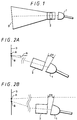
- FIG. 1 of the accompanying drawings schematically shows an image projection system which includes a CRT (cathode ray tube) 1, a lens 2 and a screen 3 disposed with an illustrated positional relationship.
- the image projection system shown in FIG. 1 can project an image obtained on an image field onto a screen insofar as the CRT 1 and the lens 2 are properly placed relative to the screen 3. Therefore, if the lens 2 is disposed at a predetermined position (angle) determined by the image filed of the image projection system, such as the CRT 1 and the screen 3, it is possible to correctly project an image onto the screen 3.
- There is an image projection system of a spacer type which includes spacers interposed in respective areas between the lens 2 and the image field of the CRT 1 to provide a necessary angle.
- the image projection system of the spacer type includes only one pattern of optical system, then it is sufficient that the image field of the CRT 1 and the lens 2 are fixed at a predetermined angle with rigid spacers.
- a relationship between the surface of the screen 3 and the image field of the CRT 1 is changed variously with a combination of a screen size and an incident angle a (see FIG. 2A).
- reference symbol ⁇ V represents an angle (declination) in the vertical direction formed by the video screen of the CRT 1 and the end face of the lens 2 as seen from the side surface direction of the set position of the CRT 1 and the lens 2 (see FIG. 2A).
- Reference symbol ⁇ H represents an angle (declination) in the horizontal direction formed by the video surface of the CRT 1 and the end face of the lens 2 as seen from the upper surface direction of the set position of the CRT 1 and the lens 2 (see FIG. 2B).
- a center A of the screen 3 and an optical axis center B are not always coincident.
- the angle ⁇ H is small. If the size of the screen 3 is small, then the angle ⁇ H is large. The incident angle ⁇ is changed variously in respective cases.
- predetermined angles can reliably determined in several fundamental optical systems but angles larger than the predetermined angles cannot be fine adjusted.
- angles other than those of the fundamental optical system are required, special spacers should be prepared additionally. If the thickness of the spacer itself is made variable, then the spacer itself becomes expensive. Also, those who adjust the spacer angle are required to become skillful.
- the lens and the video screen (CRT, etc.) are coupled with a gimbal structure having independent vertical and horizontal axes without using the spacer, accuracy between the respective axes and the bearings and a countermeasure for removing a vibration are low in reliability and disadvantageous from a cost standpoint. Moreover, upon adjustment, those who are skilled in adjustment are also required.
- an aim of the present invention to provide an image projection system of a spacer type in which an angle of a spacer can be adjusted by those who are not so skilled.
- an image projection system for projecting an image obtained on an image field onto a screen through a projection lens.
- the image projection system comprises a plurality of spacers overlaid with each other and arranged between the image field and the lens, each of the spacers having first and second surfaces through which the image is projected and an angle defined by the first and second surfaces being a predetermined value, an adjusting device for each of the spacers for adjusting a rotational angle of the spacers on a rotational axis substantially parallel to an image projection direction and a fixing device for fixing the plurality of spacers relative to the image field and the lens.
- reference symbol ⁇ V assumes an angle (declination) in the vertical direction formed by the video screen of the CRT 1 and the end face of the lens 2 as seen from the side surface direction of the set position of the CRT 1 and the lens 2 (see FIG. 2A).
- Reference symbol ⁇ H assumes an angle (declination) in the horizontal direction formed by the video screen of the CRT 1 and the end face of the lens 2 as seen from the upper surface direction of the set position of the CRT 1 and the lens 2 (see FIG. 2B).
- spacers 5a, 5b whose respective end faces have predetermined angles are inserted between the CRT 1 and the lens 2. It is possible to obtain an arbitrary declinations expressed by the angles ⁇ V and ⁇ H between the CRT 1 and the lens 2 by rotating the spacers 5a, 5b in the direction shown by an arrow A in FIG. 3A, i.e., rotating the spacers 5a, 5b about a rotation axis which is the direction (z-axis direction in FIG. 3B) through which an image from the CRT 1 passes the spacers 5a, 5b toward the lens 2.
- These declinations ⁇ V, ⁇ H are intrinsic angles determined by the combination of the CRT and the lens.
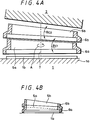
- FIGS. 4A and 4B are fragmentary enlarged cross-sectional views showing a spacer portion in which the two spacers 5a, 5b are disposed as shown in FIG. 3A.
- FIG. 4A shows a positional relationship among the CRT 1, the spacers 5a, 5b and the lens 2.
- the spacers 5a, 5b respectively include guides 6a, 6b integrally formed therewith.
- FIG. 4B shows the state that the spacers 5a, 5b are set by the guides 1b, 6a, 6b. Therefore, when the guides 6a, 6b are each rotated about a virtual rotation axis 7 in the arrow A direction (see FIG. 4A) by a rotation angle adjustment apparatus (not shown), the spacers 5a, 5b are rotated together with the guides 6a, 6b.
- Reference symbol ⁇ c1 assumes an angle formed by the respective end faces of the spacer 5a.
- Reference symbol ⁇ c2 assumes an angle formed by the respective end faces of the spacer 5b. Then, the spacer 5b is rotated on the plane inclined by the spacer 5a at the angle ⁇ c1 relative to the face plate 1a of the CRT 1. As a consequence, an angle 2 ⁇ c formed by the two spacers 5a, 5b relative to the face plate 1a of the CRT 1 is expressed by the following equation (1): 2 ⁇ c ⁇ ⁇ c1 + ⁇ c2
- the face plate 1a of the CRT 1 and one end face of the spacer 5a on its side opposing the CRT 1 are brought in the parallel state, and on end face of the spacer 5b at its side opposing the lens 2 and the end face of the lens 2 at its side opposing the end face of the spacer 5b are brought in the parallel state.
- the spacers 5a, 5b are secured between the CRT 1 and the lens 2 with some suitable means, such as screws 8 at the respective corners of the lens 2 (only one screw 8 is shown in FIG. 3A).
- some suitable means such as screws 8 at the respective corners of the lens 2 (only one screw 8 is shown in FIG. 3A).
- a lower side of the face plate 1a of the CRT 1 seen from the direction opposing the face plate 1a is assumed to be a positive direction of the Y axis
- a right-hand side thereof is assumed to be a positive direction of the X axis
- this side is assumed to be a positive direction of the Z axis.
- the Z axis shown in FIG. 3B is assumed to be a rotational axis of the spacer 5a and its rotational angle relative to the X axis is assumed to be ⁇ A
- a normal of the spacer 5b relative to the center of the end face facing the spacer 5a is assumed to be a rotational axis of the spacer 5b
- a rotational angle relative to a base line (FIG. 5) of the spacer 5a is assumed to be ⁇ B .
- This state is illustrated in FIG. 5.
- the rotational angles ⁇ A , ⁇ B are 0 degree and 180 degrees, respectively.
- iB (cos ⁇ sin ⁇ (1-cos ⁇ B ), -sin ⁇ sin ⁇ B , 1-sin2 ⁇ (1-cos ⁇ B ))
- the length of the radius of this circular locus corresponds to sin ⁇ .
- An elevation angle ⁇ 2 is expressed by using the angles ⁇ V, ⁇ H as follows:
- the rotational angle ⁇ A of the spacer 5a relative to the x axis with the Z axis shown in FIG. 3B as the rotation axis and the rotational angle ⁇ B of the spacer 5b with the normal perpendicular to its center of the end face opposing the spacer 5a as the rotation axis and relative to the base line of the spacer 5a can be calculated with ease.
- the image projection system according to the present invention is simple in arrangement in which the spacer 5 includes the guide 6 and only the rotational angle of the guide 6 is adjusted.
- the image projection system according to the embodiment of the present invention can be made inexpensive.
- the image projection system according to the present invention need not prepare the spacer 5 for every optical system separately, parts thereof need not be changed when the rotational angle of the spacer 5 is adjusted.
- a rotational angle fixing means having a proper pressing force, such as the screw 8 disposed between the lens 2 and the image field of the CRT 1 (face plate 1a), a spring or the like, not shown in FIG. 3A, then it becomes possible for the user to adjust the rotational angle while watching a picture on the screen 3 in actual practice.
- the manufacturing cost of the spacer can be reduced. Also, since the different spacers need not be prepared for every optical system, the parts of the image projection system need not be changed when the rotational angle of the spacer is adjusted.
Landscapes
- Engineering & Computer Science (AREA)
- Multimedia (AREA)
- Signal Processing (AREA)
- Transforming Electric Information Into Light Information (AREA)
- Projection Apparatus (AREA)
- Liquid Crystal (AREA)
Applications Claiming Priority (3)
| Application Number | Priority Date | Filing Date | Title |
|---|---|---|---|
| JP201056/93 | 1993-07-21 | ||
| JP20105693 | 1993-07-21 | ||
| JP5201056A JPH0738828A (ja) | 1993-07-21 | 1993-07-21 | 投射型映像表示装置 |
Publications (3)
| Publication Number | Publication Date |
|---|---|
| EP0635975A2 true EP0635975A2 (fr) | 1995-01-25 |
| EP0635975A3 EP0635975A3 (fr) | 1995-05-10 |
| EP0635975B1 EP0635975B1 (fr) | 1999-09-15 |
Family
ID=16434668
Family Applications (1)
| Application Number | Title | Priority Date | Filing Date |
|---|---|---|---|
| EP94305258A Expired - Lifetime EP0635975B1 (fr) | 1993-07-21 | 1994-07-18 | Système de projection d'images |
Country Status (5)
| Country | Link |
|---|---|
| US (1) | US5422692A (fr) |
| EP (1) | EP0635975B1 (fr) |
| JP (1) | JPH0738828A (fr) |
| KR (1) | KR100293487B1 (fr) |
| DE (1) | DE69420646T2 (fr) |
Cited By (1)
| Publication number | Priority date | Publication date | Assignee | Title |
|---|---|---|---|---|
| WO2006058810A1 (fr) * | 2004-11-30 | 2006-06-08 | Robert Bosch Gmbh | Dispositif et procede pour relier un premier composant optique a un second composant optique |
Families Citing this family (2)
| Publication number | Priority date | Publication date | Assignee | Title |
|---|---|---|---|---|
| JPH09163273A (ja) * | 1995-12-08 | 1997-06-20 | Sony Corp | プロジェクタ装置 |
| US5800032A (en) * | 1996-05-14 | 1998-09-01 | Nikon Corporation | Self correcting projector |
Family Cites Families (9)
| Publication number | Priority date | Publication date | Assignee | Title |
|---|---|---|---|---|
| JPS60264172A (ja) * | 1984-06-12 | 1985-12-27 | Mitsubishi Electric Corp | 投写装置 |
| US4753519A (en) * | 1984-09-27 | 1988-06-28 | Matsushita Electric Industrial Co., Ltd. | Optical system for projection television apparatus |
| US4606628A (en) * | 1984-12-04 | 1986-08-19 | Vivid Systems Incorporated | Video projector lens angulation mechanism |
| US4672458A (en) * | 1984-12-28 | 1987-06-09 | North American Philips Corporation | Projection television systems having lens tilt compensation member |
| JPS6221383A (ja) * | 1985-07-19 | 1987-01-29 | Matsushita Electric Ind Co Ltd | ビデオプロジエクタ |
| JPH02116284A (ja) * | 1988-10-26 | 1990-04-27 | Pioneer Electron Corp | 3管式プロジェクションテレビ |
| JP3193062B2 (ja) * | 1990-12-26 | 2001-07-30 | パイオニア株式会社 | 3管式プロジェクションテレビ |
| JP2949916B2 (ja) * | 1991-07-05 | 1999-09-20 | ソニー株式会社 | プロジェクター |
| JP3271280B2 (ja) * | 1991-12-18 | 2002-04-02 | ソニー株式会社 | プロジェクタ装置用陰極線管装置 |
-
1993
- 1993-07-21 JP JP5201056A patent/JPH0738828A/ja active Pending
-
1994
- 1994-07-18 EP EP94305258A patent/EP0635975B1/fr not_active Expired - Lifetime
- 1994-07-18 DE DE69420646T patent/DE69420646T2/de not_active Expired - Fee Related
- 1994-07-20 KR KR1019940017489A patent/KR100293487B1/ko not_active Expired - Fee Related
- 1994-07-20 US US08/277,616 patent/US5422692A/en not_active Expired - Lifetime
Cited By (1)
| Publication number | Priority date | Publication date | Assignee | Title |
|---|---|---|---|---|
| WO2006058810A1 (fr) * | 2004-11-30 | 2006-06-08 | Robert Bosch Gmbh | Dispositif et procede pour relier un premier composant optique a un second composant optique |
Also Published As
| Publication number | Publication date |
|---|---|
| KR100293487B1 (ko) | 2001-09-17 |
| EP0635975B1 (fr) | 1999-09-15 |
| DE69420646T2 (de) | 2000-04-06 |
| EP0635975A3 (fr) | 1995-05-10 |
| JPH0738828A (ja) | 1995-02-07 |
| US5422692A (en) | 1995-06-06 |
| KR950005011A (ko) | 1995-02-18 |
| DE69420646D1 (de) | 1999-10-21 |
Similar Documents
| Publication | Publication Date | Title |
|---|---|---|
| US8746994B2 (en) | Auxiliary device for full-circle panoramic video imaging | |
| US6961177B2 (en) | Stereoscopic image display apparatus, display apparatus, divided wave plate filter, plate-shared filter, and filter position adjusting mechanism attached to the display apparatus, aligning apparatus, filter position adjusting method, and filter aligning method | |
| US7182464B2 (en) | Projector with adjustably positioned image plate | |
| US6567126B1 (en) | Planar focus correction | |
| CN1385725B (zh) | 保持透镜的光学装置 | |
| JP2596917B2 (ja) | 情報表示装置 | |
| US20210041714A1 (en) | Optical module having image shake correction function | |
| US5061052A (en) | Television picture enhancement device | |
| US20080192344A1 (en) | Multi-dimensional imaging apparatus, methods, and systems | |
| KR970032049A (ko) | 공간 뷰잉 및 투사 장치 | |
| EP0168794A1 (fr) | Système photographique de lentilles stabilisé optiquement | |
| US3879112A (en) | Adjustable mirror mount | |
| US4922338A (en) | Line-of-sight inspection system | |
| WO2005057918A1 (fr) | Actionneur ameliorant la resolution | |
| JPH10164414A (ja) | カメラ内蔵ノート型パーソナルコンピュータ | |
| EP0635975A2 (fr) | Système de projection d'images | |
| CN111552054A (zh) | 一种离轴三反光学系统总体设计与装调方法 | |
| US6323903B1 (en) | Three axis camera mount | |
| JP3478308B2 (ja) | テレビカメラプロンプターシステム | |
| WO2009069925A1 (fr) | Porte-objectif permettant de régler l'axe optique de l'objectif | |
| US4417273A (en) | Video projection system | |
| US6097554A (en) | Multiple dove prism assembly | |
| CN206759599U (zh) | 摄像角度转换镜及转换组件 | |
| CN117518702A (zh) | 光学系统 | |
| US4529276A (en) | Image rotating optical system |
Legal Events
| Date | Code | Title | Description |
|---|---|---|---|
| PUAI | Public reference made under article 153(3) epc to a published international application that has entered the european phase |
Free format text: ORIGINAL CODE: 0009012 |
|
| AK | Designated contracting states |
Kind code of ref document: A2 Designated state(s): DE GB |
|
| PUAL | Search report despatched |
Free format text: ORIGINAL CODE: 0009013 |
|
| AK | Designated contracting states |
Kind code of ref document: A3 Designated state(s): DE GB |
|
| 17P | Request for examination filed |
Effective date: 19951016 |
|
| 17Q | First examination report despatched |
Effective date: 19971105 |
|
| GRAG | Despatch of communication of intention to grant |
Free format text: ORIGINAL CODE: EPIDOS AGRA |
|
| GRAG | Despatch of communication of intention to grant |
Free format text: ORIGINAL CODE: EPIDOS AGRA |
|
| GRAH | Despatch of communication of intention to grant a patent |
Free format text: ORIGINAL CODE: EPIDOS IGRA |
|
| GRAH | Despatch of communication of intention to grant a patent |
Free format text: ORIGINAL CODE: EPIDOS IGRA |
|
| GRAA | (expected) grant |
Free format text: ORIGINAL CODE: 0009210 |
|
| AK | Designated contracting states |
Kind code of ref document: B1 Designated state(s): DE GB |
|
| REF | Corresponds to: |
Ref document number: 69420646 Country of ref document: DE Date of ref document: 19991021 |
|
| PLBE | No opposition filed within time limit |
Free format text: ORIGINAL CODE: 0009261 |
|
| STAA | Information on the status of an ep patent application or granted ep patent |
Free format text: STATUS: NO OPPOSITION FILED WITHIN TIME LIMIT |
|
| 26N | No opposition filed | ||
| PGFP | Annual fee paid to national office [announced via postgrant information from national office to epo] |
Ref country code: DE Payment date: 20010709 Year of fee payment: 8 |
|
| PGFP | Annual fee paid to national office [announced via postgrant information from national office to epo] |
Ref country code: GB Payment date: 20010718 Year of fee payment: 8 |
|
| REG | Reference to a national code |
Ref country code: GB Ref legal event code: IF02 |
|
| PG25 | Lapsed in a contracting state [announced via postgrant information from national office to epo] |
Ref country code: GB Free format text: LAPSE BECAUSE OF NON-PAYMENT OF DUE FEES Effective date: 20020718 |
|
| PG25 | Lapsed in a contracting state [announced via postgrant information from national office to epo] |
Ref country code: DE Free format text: LAPSE BECAUSE OF NON-PAYMENT OF DUE FEES Effective date: 20030201 |
|
| GBPC | Gb: european patent ceased through non-payment of renewal fee |
Effective date: 20020718 |