EP0635982A1 - Système de transmission de données - Google Patents
Système de transmission de données Download PDFInfo
- Publication number
- EP0635982A1 EP0635982A1 EP94305399A EP94305399A EP0635982A1 EP 0635982 A1 EP0635982 A1 EP 0635982A1 EP 94305399 A EP94305399 A EP 94305399A EP 94305399 A EP94305399 A EP 94305399A EP 0635982 A1 EP0635982 A1 EP 0635982A1
- Authority
- EP
- European Patent Office
- Prior art keywords
- data
- center
- clock
- clock signal
- terminals
- Prior art date
- Legal status (The legal status is an assumption and is not a legal conclusion. Google has not performed a legal analysis and makes no representation as to the accuracy of the status listed.)
- Withdrawn
Links
- 230000005540 biological transmission Effects 0.000 title claims abstract description 117
- 238000000034 method Methods 0.000 claims abstract description 6
- 230000005236 sound signal Effects 0.000 description 10
- 230000001360 synchronised effect Effects 0.000 description 7
- 230000002457 bidirectional effect Effects 0.000 description 6
- 238000010586 diagram Methods 0.000 description 5
- 230000001755 vocal effect Effects 0.000 description 2
- 239000002131 composite material Substances 0.000 description 1
- 238000010276 construction Methods 0.000 description 1
- 239000000284 extract Substances 0.000 description 1
- 239000000203 mixture Substances 0.000 description 1
- 238000012986 modification Methods 0.000 description 1
- 230000004048 modification Effects 0.000 description 1
Images


Classifications
-
- H—ELECTRICITY
- H04—ELECTRIC COMMUNICATION TECHNIQUE
- H04L—TRANSMISSION OF DIGITAL INFORMATION, e.g. TELEGRAPHIC COMMUNICATION
- H04L7/00—Arrangements for synchronising receiver with transmitter
- H04L7/0008—Synchronisation information channels, e.g. clock distribution lines
-
- H—ELECTRICITY
- H04—ELECTRIC COMMUNICATION TECHNIQUE
- H04N—PICTORIAL COMMUNICATION, e.g. TELEVISION
- H04N7/00—Television systems
- H04N7/16—Analogue secrecy systems; Analogue subscription systems
- H04N7/173—Analogue secrecy systems; Analogue subscription systems with two-way working, e.g. subscriber sending a programme selection signal
- H04N7/17309—Transmission or handling of upstream communications
- H04N7/17318—Direct or substantially direct transmission and handling of requests
Definitions
- the present invention relates to a data transmission system wherein a center and a plurality of terminals are connected by a transmission line, the data transmission system being for performing bidirectionally transmission of data between the center and the terminals.
- CATV bidirectional cable television
- the clock in a terminal must be synchronized with the clock in the center before data can be transmitted or received.
- the following operations be performed in each terminal.
- the right to transmit is transferred from one terminal to another.
- a terminal receives from the center a signal requesting to connect circuits (polling signal)
- the terminal extracts the component of the connection request that corresponds to the clock of the center.
- the terminal demodulates the clock component into a reference clock signal that is synchronized with the clock of the center. Transmission of data to and reception of data from the center is then performed based on the reference clock.
- the present invention provides a data transmission system for bidirectionally transmitting data between a center and a plurality of terminals, the data transmission system comprising: a center and a plurality of terminals connected to the center by a transmission line, the center being for transmitting data to and receiving data from the plurality of terminals over the transmission line over at least one channel, and the center including clock transmission means for transmitting a clock signal over a predetermined channel that is different from the at least one channel over which data is transmitted to and from the center.
- the clock transmission means preferably includes: clock pulse generating means for generating a clock pulse, based on which the center transmitting data to and receiving data from the plurality of terminals; and clock pulse modulating means for modulating the clock pulse into a clock signal of the predetermined channel.
- At least one of the plurality of terminals preferably includes: reference clock demodulation means for demodulating the clock signal from the center into a reference clock signal that is in synchronization with the clock pulse generated in the clock pulse generating means and for outputting the reference clock signal; and transmission/reception means for transmitting data to and receiving data from the center based on the reference clock signal.
- the present invention provides a data transmission device for transmitting data to and receiving data from a plurality of terminals connected to the data transmission device via a transmission line, the data transmission device comprising: clock transmission means for continuously transmitting a clock signal over a predetermined channel via a transmission line to a plurality of terminals; and data transmission/reception means for transmitting data to and receiving data from the plurality of terminals via the transmission line over at least one channel different from the predetermined channel.
- the present invention provides a method of bidirectionally transmitting data between a center and a plurality of terminals connected to the center by a transmission line, the method comprising the steps of: continuously transmitting a clock signal from the center to at least one of the plurality of terminals over a predetermined channel; demodulating at the at least one of the plurality of terminal the clock signal from the center into a reference clock signal that is in synchronization with the clock signal from the center; performing transmission and reception of data, based on the reference clock signal, between the center and the at least one of the plurality of terminals over at least one channel that is different from the predetermined channel over which the clock signal is transmitted from the center.
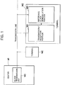
- Fig. 1 shows a schematic representation of the data transmission system according to the preferred embodiment.
- the data transmission system is for bidirectionally transmitting data between a center M1 and a plurality of terminals M2.
- the center M1 is connected to the plurality of terminals M2 with a transmission line.
- the center M1 produces a clock pulse, based on which the center M1 performs transmission and reception of data with the terminals M2 via the transmission line over at least one channel C1.
- the center M1 includes a clock transmission unit M3 for continuously transmitting a clock signal corresponding to the clock pulse, via the transmission line through a channel C2 different from the channel C1.
- At least one terminal of the plurality of terminals M2 includes a reference clock demodulation portion M5 for receiving the clock signal transmitted from the center M1 and demodulating the clock signal into a reference clock signal synchronized with the clock pulse.
- the at least one terminal M2 further includes a transmission/reception portion M4 connected to the reference clock demodulation portion M5 for performing transmission and reception of data with the center based on the reference clock signal.
- the center M1 is controlled to perform data transmission and reception operation in accordance with the clock pulse generated therein.
- the clock transmission unit M3 modulates the clock pulse into the clock signals and continuously transmits the clock signal to the at least one terminal that has the transmission/reception portion M4 and the reference clock demodulation portion M5.
- the reference clock demodulation portion M5 demodulates the clock signal into a reference clock signal which is synchronized with the clock pulse.
- the transmission/reception portion M4 performs transmission and reception of data with the center, in accordance with the reference clock signal.
- the center M1 and the at least one terminals M2 are synchronously controlled to perform bidirectional transmission and reception of data therebetween.
- the clock transmission unit M3 provided to the center M1 uses the predetermined channel C2 for transmitting a clock signal.
- the predetermined channel C2 for transmitting the clock signal is not used for transmitting data.
- the reference clock demodulation portion M5 provided to at least one terminal M2 continually demodulates the clock signal from the center and produces a reference clock signal that is synchronized with the center clock pulse. That is, the transmitted clock signal becomes a reference clock signal to be used in the terminal during the transmission and reception of data.
- the transmission/reception portion M4 can therefore transmit data to or receive data from the center based on the reference clock signal, as soon as the right of transmission has been transferred to the terminal. Accordingly, the preamble can be eliminated and transmission and reception of data can be quickly executed.
- Fig. 2 is a block diagram showing overall construction of a concrete example of a bidirectional CATV system to which applied is the preferred embodiment of Fig. 1.
- the CATV system includes a center S and a plurality of terminals 11.
- the center S is connected with the plurality of terminals 11 by a transmission line 9.
- a host CPU 1 is provided to perform overall control operation of the center S.
- a character/image data output device 2 is connected to the host CPU 1.
- the device 2 is controlled by the host CPU 1 to output both character data representing images of alphanumeric characters such as written messages and advertisements and image data representing images of still pictures.
- Examples of the character data may include lyric data for karaoke songs, for being projected on television receivers 12 connected to the terminals 11 during karaoke performances achieved at the terminals 11.
- Examples of the image data may include image data of a composite image where a song title of each karaoke song is superimposed on a corresponding background still picture image, for being projected on the television receivers 12 at the start of the karaoke performance achieved at the terminals 11. (The character data and/or the image data will be referred to as "character/image data,” hereinafter.)
- a modulator 3 is provided for modulating the character/image data outputted from the character/image data output device 2 into character/image signals (alternating current signals) of at least one channel (frequency band) Ca.
- the modulator 3 is connected to a head amplifier (which is also called a "mixer/frequency divider") 4.
- the modulator 3 outputs the modulated signals to the head amplifier 4.
- a video/sound program output device 5 is provided for preparing video/sound programs which are to be provided by this CATV system to users of the system.
- the device 5 outputs video/sound signals representing various video/sound programs. Examples for the device 5 may include a broadcast satellite reception system for outputting broadcast satellite signals (image signals and sound signals) and a video player for outputting video signals.
- a modulator 6 is connected to the device 5 to receive the video/sound signals outputted therefrom.
- the modulator 6 modulates the video/sound signals into alternating current signals of at least one channel Cb (frequency band) which is different from the channel Ca.
- the modulator 6 is also connected to the head amplifier 4.
- the modulator 6 outputs the modulated video/sound signals to the head amplifier 4 connected thereto.
- the host CPU 1 also serves to produce various data to be transmitted to the terminals. More specifically, the host CPU 1 produces various control data. Examples of the control data may include polling data to be used for polling operation of the terminals 11, tuner control data used for tuner channel selection control operation for tuners 16 of the terminals 11, and various program data.
- the host CPU 1 also produces various image data and various sound data. For example, the host CPU 1 produces instrumental or vocal accompaniment sound data, for being played by sound sources (not shown) in the terminals 11 during karaoke performances achieved at the terminals 11.
- a control CPU 7 is connected to the host CPU 1.
- the control CPU 7 is controlled by the host CPU 1 to perform overall control of data transmission/reception operation of the center S.
- the control CPU 7 continually generates clock pulses.
- the control CPU 7 is controlled by the host CPU 7 to perform its data transmission and reception operation, at timings based on the clock pulses.
- a data modem 8 is connected to the control CPU 7.
- the control CPU 7 transfers the various data outputted from the host CPU 1 to the data modem 8.
- the control CPU 7 controls the data modem 8 to modulate the received various data into data (alternating current signals) of at least one channel Cc (frequency band) different from the channels Ca and Cb and to output the modulated data to the head amplifier 4.
- the control CPU 7 controls the data modem 8 to modulate and output the data, at timings determined dependently on the clock pulses.
- the control CPU 7 also controls the data modem 8 to receive and demodulate various data, such as request data, transmitted from the terminals 11 via the head amplifier 4.
- the control CPU 7 controls the data modem 8 to receive and demodulate the transmitted data, at timings determined dependently on the clock pulses.
- the demodulated data are supplied via the control CPU 7 to the host CPU 1.
- a clock modulator 10 is also connected to the control CPU 7.
- the clock modulator 10 continually receives the clock pulses generated from the control CPU 7 and modulates them into clock signals (alternating current signals) of one channel Cd (frequency band) different from any of the channels Ca, Cb and Cc.
- the clock modulator 10 outputs the clock signals to the head amplifier 4.
- the head amplifier 4 is connected to the modulators 3 and 6, the data modem 8 and the clock modulator 10 for receiving input of the variety of signals outputted therefrom.
- the head amplifier 4 mixes the inputted signals, and transmits the mixed signals as outgoing signals over the transmission line 9 to an appropriate terminal of the plurality of terminals 11.
- the head amplifier 4 multiplexes the character/image signals (from device 2), the video/sound signals (from device 5), the various data (from CPU 1) and the clock signals (from device 10) which have been modulated into the different channels Ca - Cd. Then, the head amplifier 4 outputs the multiplexed signals to the transmission line 9.
- the clock signals, modulated by the clock modulator 10 are transmitted over the channel Cd that is different from the channels over which the signals from the data modem 8 or the modulators 3 and 6 are transmitted. Accordingly, it is possible to continuously transmit the clock signals to the terminals 11.
- Each of the plurality of terminals 11 is connected to a television receiver 12.
- the terminals 11 receive the outgoing signals (character/image signals, video/sound signals, various data and clock signals) from the head amplifier 4 and drives the television receivers 12 in accordance with the received outgoing signals.
- Fig. 3 is a block diagram showing the configuration of components in each terminal 11.
- each terminal 11 includes a branch 15 into which the outgoing signals transmitted over the transmission line 9 are inputted.
- the branch 15 is connected by separate three lines to a tuner 16, a data modem 22, and a clock demodulator 25.
- the branch 15 therefore diverges signals from the center S to the three lines. More specifically, the branch 15 diverges the character/image signals and the video/sound signals to the tuner 16, diverges the various data from the host CPU 1 to the data modem 22, and diverges the clock signals to the clock demodulator 25.
- the clock demodulator 25 continually demodulates the clock signals into reference clock signals that are in synchronization with the clock pulses generated at the control CPU 7 in the center S.
- the clock demodulator 25 outputs the reference clock signals to a terminal control CPU 23.
- the terminal control CPU 23 performs data transmission and data reception control operation of the terminal 11, at timings based on the reference clock signals. Accordingly, the terminal control CPU 23 can perform data transmission and reception operation, at timings synchronized with the clock pulses of the control CPU 7.
- the data modem 22 is connected to the terminal control CPU 23.
- the terminal control CPU 23 controls the data modem 22 to receive and demodulate various data transmitted from the host CPU 1 of the center S, at timings of the reference clock signals.
- the terminal control CPU 23 also controls the data modem 22 to modulate and transmit various types of data, such as request data, to the center S at timings of the reference clock signals.
- the clock signals are continuously transmitted to the terminal 11 over the predetermined channel Cd different from the channels Ca - Cc over which other various signals are transmitted. Accordingly, the terminal control CPU 23 can always perform the data transmission and reception operation.
- the terminal CPU 23 processes the various data transmitted from the host CPU 1 of the center 3. For example, if the received data is the tuner control data, the terminal CPU 23 controls the tuner 16 to select a desired channel. If the received data is the accompaniment sound data, the CPU 23 controls the sound source (not shown) to play a desired karaoke accompaniment sound.
- the CPU 23 also performs to generate various data to be transmitted to the center S, such as request data requesting transmission of desired data.
- the data modem 22 modulates the data outputted from the CPU 23 and transmits them to the center S.
- the tuner 16 receives the character/image signals and the video/sound signals supplied from the center 3.
- the terminal control CPU 23 controls the tuner 16 in accordance with the received tuner control data.
- the tuner 16 selects a desired one of the channels Ca and Cb to supply a desired one of the character/image signals and the video/sound signals to the television receiver 12.
- the CATV system having the above structure operates, as will be described below.
- the control CPU 7 continuously generates clock pulses, and the clock modulator 10 continuously modulates the clock pulses into clock signals of the channel Cd.
- the head amplifier 4 transmits the clock signals via the transmission line 9 to each of the plurality of terminals 11.
- the branch 15 diverges the clock signals to the clock demodulator 25, which continuously demodulates the clock signals into the reference clock signals and outputs them to the terminal control CPU 23.
- the reference clock signals are in synchronization with the clock pulses of the control CPU 7.
- the host CPU 1 performs polling to all the terminals 11 in succession, to thereby operationally connect the transmission line between the center 3 and the respective terminals 11. More specifically, the host CPU 1 generates polling data one by one for all the terminals 11.
- the polling data outputted from the host CPU 1 are supplied to the control CPU 7.
- the control CPU 7 controls to transmit the polling data from the host CPU 1 to the terminals 11, at timings determined dependently on the clock pulses generated in the CPU 7. More specifically, the control CPU 7 controls the data modem 8 to modulate the polling data into data of the channel Cc and to output the polling data toward the transmission line 9, at timings determined dependently on the clock pulses.
- the branch 15 diverges the received corresponding polling data to the data modem 22.
- the terminal control CPU 23 always being supplied with the reference clock signals can always perform its data transmission/reception operation at timings determined dependently on the reference clock signals. Accordingly, the terminal control CPU 23 controls the data modem 22 to demodulate the polling data transmitted from the center S, at timings of the reference clock signals.
- the terminal control CPU 23 If the terminal 11 does not require transmission of any data from the center S, the terminal control CPU 23 generates a request data indicating that the terminal 11 has made no request. On the other hand, if the terminal 11 requires transmission of data (character/image data, video/sound data or other various data) from the center S, the terminal control CPU 23 generates a request data indicating that the terminal has made a request and including the content of the request.
- the terminal control CPU 23 controls the data modem 22 to modulate the request data and to transmit the modulated request data to the transmission line 9 via the branch 15, at timings of the reference clock signals.
- the modulated request data received at the head amplifier 4 are supplied to the data modem 8, where the request data are demodulated and supplied via the control CPU 7 to the host CPU 1, at timings of the clock pulses.
- the host CPU 1 controls the character image output device 2 to output the character/image data.
- the CPU 1 also produces tuner control data for controlling the tuner 16 of the terminal 11 to select the channel Ca for receiving the character/image data.
- the request data requests transmission of the video/sound program data
- the CPU 1 produces tuner control data for controlling the tuner 16 of the terminal 11 to select the channel Cb for receiving the video/sound program data.
- the request data requests transmission of other various data, for example, instrumental or vocal accompaniment sound data for karaoke performance
- the host CPU 1 produces the requested data.
- Data outputted from the character/image data output device 2 or the video/sound program output device 5 are modulated for transmission to the channel Ca or Cb, at the modulator 3 or 6.
- the control CPU 7 controls to transmit the data from the host CPU 1 to the terminal 11 which has made the request, at timings determined dependently on the clock pulses generated in the CPU 7. More specifically, the control CPU 7 controls the data modem 8 to modulate the data into data of the channel Cc and to output the data toward the transmission line 9, at timings determined dependently on the clock pulses.
- modulated signals from the modulator 3 or 6 and from the modem 8 are mixed with the modulated clock signals (channel Cd) in the head amplifier 4 and transmitted to the terminal 11 that has made the request.
- the terminal 11 receives the incoming mixed signals from the center S at the branch 15.
- the branch 15 divides the mixed signals into the character/image signals or the video/sound program signals, the various data from the host CPU and the clock signals.
- the character/image signals or the video/sound program signals are supplied to the tuner 16.
- the terminal control CPU 23 performs its data transmission/reception operation at timings determined dependently on the reference clock signals. More specifically, the terminal control CPU 23 controls the data modem 22 to demodulate the data transmitted from the host CPU 1 and to supply the demodulated data into the control CPU 23, at timings of the reference clock signals. Accordingly, the terminal control CPU 23 can properly receive the various data transmitted from the host CPU 1 of the center S at timings of the clock pulses.
- the terminal control CPU 23 controls the tuner 16 to select the channel Ca or Cb so as to supply the requested character/image or video/sound program to the television receiver 12. If the data supplied to the control CPU 23 is the accompaniment sound data for the karaoke performance, the control CPU 23 controls the sound source (not shown) to output the accompaniment sound.
- the center is continually transmitting, and the terminal is constantly demodulating, clock signals, no time is required for synchronizing the clocks of CPUs 7 and 23. That is, the time consumed during the preamble is eliminated. Transmission and reception of data can be quickly executed as soon as the right of transmission is transferred to the corresponding terminal 11, i.e., as soon as the corresponding terminal 11 receives the polling signal. Accordingly, in the present invention, one center S can be connected to a great number of terminals 11.
- the clock signal is transmitted via a predetermined channel Cd that is not used for transmitting data, the clock signal can be prevented from erroneously mixing with other data.
- the clock demodulator 25 is provided to each of the plurality of terminals 11.
- the clock demodulator 25 can be provided to only one or more terminals 11.
- the other terminals 11 can be synchronized, according to a clock component included in a connection request (polling signal) sent from the center S for data transmission and reception.
- the preamble can be eliminated when dealing with terminals provided with the clock demodulator 25. In this way, transmission and reception of data can be quickly executed in terms of the overall device.
- the present invention is applied to a bidirectional CATV device.
- the present invention can be applied to other types of data transmission devices.
Landscapes
- Engineering & Computer Science (AREA)
- Signal Processing (AREA)
- Computer Networks & Wireless Communication (AREA)
- Multimedia (AREA)
- Two-Way Televisions, Distribution Of Moving Picture Or The Like (AREA)
- Small-Scale Networks (AREA)
Applications Claiming Priority (2)
| Application Number | Priority Date | Filing Date | Title |
|---|---|---|---|
| JP180340/93 | 1993-07-21 | ||
| JP5180340A JPH0738586A (ja) | 1993-07-21 | 1993-07-21 | データ伝送装置 |
Publications (1)
| Publication Number | Publication Date |
|---|---|
| EP0635982A1 true EP0635982A1 (fr) | 1995-01-25 |
Family
ID=16081517
Family Applications (1)
| Application Number | Title | Priority Date | Filing Date |
|---|---|---|---|
| EP94305399A Withdrawn EP0635982A1 (fr) | 1993-07-21 | 1994-07-21 | Système de transmission de données |
Country Status (4)
| Country | Link |
|---|---|
| US (1) | US5612681A (fr) |
| EP (1) | EP0635982A1 (fr) |
| JP (1) | JPH0738586A (fr) |
| CN (1) | CN1108843A (fr) |
Families Citing this family (10)
| Publication number | Priority date | Publication date | Assignee | Title |
|---|---|---|---|---|
| US5734329A (en) * | 1995-07-13 | 1998-03-31 | Dell Usa L.P. | Method and apparatus for superimposing self-clocking multifunctional communications on a static digital signal line |
| JP2985750B2 (ja) * | 1995-10-19 | 1999-12-06 | ヤマハ株式会社 | 通信カラオケ装置の情報ファイル管理方法および通信カラオケ装置 |
| JPH09127962A (ja) * | 1995-10-31 | 1997-05-16 | Pioneer Electron Corp | カラオケデータの送信方法および送受信装置 |
| EP0813321A3 (fr) * | 1996-06-14 | 2001-05-09 | TEMIC TELEFUNKEN microelectronic GmbH | Méthode et système de commande pour la transmission de données numérique |
| US6091772A (en) * | 1997-09-26 | 2000-07-18 | International Business Machines, Corporation | Black based filtering of MPEG-2 compliant table sections |
| DE19813965C1 (de) * | 1998-03-28 | 1999-08-19 | Telefunken Microelectron | Verfahren zum Übertragen von digitalen Datenimpulsen mit einem in seiner Taktfrequenz steuerbaren Datenübernahmetaktgenerator |
| KR20000027466A (ko) * | 1998-10-28 | 2000-05-15 | 구자홍 | 양방향 통신 장치 |
| JP2002300482A (ja) * | 2001-03-30 | 2002-10-11 | Sanyo Electric Co Ltd | デジタルテレビ放送受信機 |
| FR2850511B1 (fr) * | 2003-01-28 | 2005-06-03 | St Microelectronics Sa | Terminal d'utilisateur pour systeme de telediffusion numerique interactive |
| CN119485628A (zh) * | 2025-01-09 | 2025-02-18 | 四川海格恒通专网科技有限公司 | 多载波基站及其同步方法、电子设备和存储介质 |
Citations (2)
| Publication number | Priority date | Publication date | Assignee | Title |
|---|---|---|---|---|
| US4225939A (en) * | 1976-04-16 | 1980-09-30 | Pioneer Electronic Corporation | Bidirectional data communication system |
| GB2246930A (en) * | 1987-11-02 | 1992-02-12 | Videotron Ltd | Bidirectional cable communication system and apparatus |
Family Cites Families (13)
| Publication number | Priority date | Publication date | Assignee | Title |
|---|---|---|---|---|
| US4031543A (en) * | 1974-03-11 | 1977-06-21 | Berkeley Varitronics Systems | Communication system |
| JPS5946143B2 (ja) * | 1976-04-16 | 1984-11-10 | パイオニア株式会社 | 双方向catvシステムにおける伝送確認方法および装置 |
| US4231114A (en) * | 1978-02-27 | 1980-10-28 | Motorola, Inc. | Synchronizing means for a two-way communication system |
| US4343042A (en) * | 1979-07-10 | 1982-08-03 | Cablebus Systems Corporation | Bi-directional data transmission and control system |
| US4340961A (en) * | 1980-03-06 | 1982-07-20 | Atomic Energy Of Canada Limited | Distributed multi-port communications system |
| NL8500462A (nl) * | 1985-02-19 | 1986-09-16 | Philips Nv | Inrichting voor het overdragen van digitale data. |
| US4860006A (en) * | 1986-06-05 | 1989-08-22 | Michael Barall | Heartbeat collision avoidance method and circuit |
| JP2579963B2 (ja) * | 1987-10-26 | 1997-02-12 | シャープ株式会社 | 通信方式 |
| US4989203A (en) * | 1989-06-09 | 1991-01-29 | Honeywell Inc. | Apparatus for providing multiple controller interfaces to a standard digital modem and including separate contention resolution |
| US5025500A (en) * | 1989-06-09 | 1991-06-18 | Honeywell Inc. | Apparatus for providing multiple controller interfaces to a standard digital modem and including integral conflict resolution |
| US5263163A (en) * | 1990-01-19 | 1993-11-16 | Codex Corporation | Arbitration among multiple users of a shared resource |
| EP0562222B1 (fr) * | 1992-03-27 | 1999-05-12 | Alcatel | Dispositif pour le contrÔle d'accès |
| US5376928A (en) * | 1992-09-18 | 1994-12-27 | Thomson Consumer Electronics, Inc. | Exchanging data and clock lines on multiple format data buses |
-
1993
- 1993-07-21 JP JP5180340A patent/JPH0738586A/ja active Pending
-
1994
- 1994-07-20 US US08/277,744 patent/US5612681A/en not_active Expired - Lifetime
- 1994-07-21 CN CN94108156A patent/CN1108843A/zh active Pending
- 1994-07-21 EP EP94305399A patent/EP0635982A1/fr not_active Withdrawn
Patent Citations (2)
| Publication number | Priority date | Publication date | Assignee | Title |
|---|---|---|---|---|
| US4225939A (en) * | 1976-04-16 | 1980-09-30 | Pioneer Electronic Corporation | Bidirectional data communication system |
| GB2246930A (en) * | 1987-11-02 | 1992-02-12 | Videotron Ltd | Bidirectional cable communication system and apparatus |
Non-Patent Citations (1)
| Title |
|---|
| K. MAEDA: "Individualized Still- Picture Communication on a Two- Way Broad- Band CATV System", IEEE TRANSACTIONS ON COMMUNICATIONS, vol. COM-23, no. 1, January 1975 (1975-01-01), pages 104 - 107, XP002053709, DOI: doi:10.1109/TCOM.1975.1092660 * |
Also Published As
| Publication number | Publication date |
|---|---|
| US5612681A (en) | 1997-03-18 |
| CN1108843A (zh) | 1995-09-20 |
| JPH0738586A (ja) | 1995-02-07 |
Similar Documents
| Publication | Publication Date | Title |
|---|---|---|
| US6751800B1 (en) | Information processing apparatus, method, and computer-readable medium | |
| US6215781B1 (en) | Video transmitting apparatus | |
| KR940013219A (ko) | 동조조작용멀티스크린디스플레이를갖는텔레비전신호송신및수신시스템 | |
| JPH08251124A (ja) | 無線情報放送システム | |
| US5612681A (en) | Data transmission system having dedicated clock channel | |
| JP2000504527A (ja) | テレビジョンプログラム及び付加的データサービスの送信及び受信 | |
| US20140055672A1 (en) | Apparatus and method for processing additional information in television | |
| US5678173A (en) | CATV system and method of judging modulation technique in CATV system | |
| JP2663919B2 (ja) | 周波数分割多元接続方式の通信システム | |
| KR20010021317A (ko) | 수신 장치 및 화상 데이터 처리 방법 | |
| KR100357160B1 (ko) | 디지탈 위성방송수신기의 영상반복장치 | |
| JP2001136444A (ja) | ディジタルテレビ受信機の番組選択装置およびその周波数変換データ取得方法 | |
| JPH09247647A (ja) | 映像音声情報配信システム | |
| JP2000253379A (ja) | 情報送受信システム及び情報受信装置並びに情報受信方法 | |
| JP3278618B2 (ja) | 番組情報伝送装置及び番組情報伝送方法 | |
| JPH10271399A (ja) | 衛星放送受信機 | |
| JPH0332275B2 (fr) | ||
| JPH07298245A (ja) | センター局装置及び端末装置 | |
| KR970011699B1 (ko) | 위성방송 자막 중첩시스템 | |
| US7136112B2 (en) | Method and apparatus for modulating video signals | |
| JPH0715394A (ja) | 文字多重通信システム | |
| JPH09224229A (ja) | ケーブルテレビ放送システム | |
| JP2002171493A (ja) | 放送システム | |
| JP2002044614A (ja) | Epgシステムおよび受信機 | |
| JPH06205383A (ja) | Catvの文字放送方式 |
Legal Events
| Date | Code | Title | Description |
|---|---|---|---|
| PUAI | Public reference made under article 153(3) epc to a published international application that has entered the european phase |
Free format text: ORIGINAL CODE: 0009012 |
|
| AK | Designated contracting states |
Kind code of ref document: A1 Designated state(s): DE GB |
|
| 17P | Request for examination filed |
Effective date: 19950626 |
|
| 17Q | First examination report despatched |
Effective date: 19970919 |
|
| STAA | Information on the status of an ep patent application or granted ep patent |
Free format text: STATUS: THE APPLICATION IS DEEMED TO BE WITHDRAWN |
|
| 18D | Application deemed to be withdrawn |
Effective date: 19980331 |