EP0636405A2 - Installation et procédé pour changer la distribution spatiale d'un solide pulvérulent - Google Patents
Installation et procédé pour changer la distribution spatiale d'un solide pulvérulent Download PDFInfo
- Publication number
- EP0636405A2 EP0636405A2 EP94110553A EP94110553A EP0636405A2 EP 0636405 A2 EP0636405 A2 EP 0636405A2 EP 94110553 A EP94110553 A EP 94110553A EP 94110553 A EP94110553 A EP 94110553A EP 0636405 A2 EP0636405 A2 EP 0636405A2
- Authority
- EP
- European Patent Office
- Prior art keywords
- solid
- fluid
- nozzle
- jet
- jet direction
- Prior art date
- Legal status (The legal status is an assumption and is not a legal conclusion. Google has not performed a legal analysis and makes no representation as to the accuracy of the status listed.)
- Ceased
Links
Images


Classifications
-
- B—PERFORMING OPERATIONS; TRANSPORTING
- B01—PHYSICAL OR CHEMICAL PROCESSES OR APPARATUS IN GENERAL
- B01J—CHEMICAL OR PHYSICAL PROCESSES, e.g. CATALYSIS OR COLLOID CHEMISTRY; THEIR RELEVANT APPARATUS
- B01J8/00—Chemical or physical processes in general, conducted in the presence of fluids and solid particles; Apparatus for such processes
- B01J8/18—Chemical or physical processes in general, conducted in the presence of fluids and solid particles; Apparatus for such processes with fluidised particles
- B01J8/1809—Controlling processes
-
- B—PERFORMING OPERATIONS; TRANSPORTING
- B01—PHYSICAL OR CHEMICAL PROCESSES OR APPARATUS IN GENERAL
- B01J—CHEMICAL OR PHYSICAL PROCESSES, e.g. CATALYSIS OR COLLOID CHEMISTRY; THEIR RELEVANT APPARATUS
- B01J2/00—Processes or devices for granulating materials, e.g. fertilisers in general; Rendering particulate materials free flowing in general, e.g. making them hydrophobic
-
- B—PERFORMING OPERATIONS; TRANSPORTING
- B01—PHYSICAL OR CHEMICAL PROCESSES OR APPARATUS IN GENERAL
- B01J—CHEMICAL OR PHYSICAL PROCESSES, e.g. CATALYSIS OR COLLOID CHEMISTRY; THEIR RELEVANT APPARATUS
- B01J8/00—Chemical or physical processes in general, conducted in the presence of fluids and solid particles; Apparatus for such processes
- B01J8/0015—Feeding of the particles in the reactor; Evacuation of the particles out of the reactor
- B01J8/003—Feeding of the particles in the reactor; Evacuation of the particles out of the reactor in a downward flow
-
- B—PERFORMING OPERATIONS; TRANSPORTING
- B01—PHYSICAL OR CHEMICAL PROCESSES OR APPARATUS IN GENERAL
- B01J—CHEMICAL OR PHYSICAL PROCESSES, e.g. CATALYSIS OR COLLOID CHEMISTRY; THEIR RELEVANT APPARATUS
- B01J2208/00—Processes carried out in the presence of solid particles; Reactors therefor
- B01J2208/00008—Controlling the process
- B01J2208/00017—Controlling the temperature
- B01J2208/00026—Controlling or regulating the heat exchange system
- B01J2208/00035—Controlling or regulating the heat exchange system involving measured parameters
- B01J2208/0007—Pressure measurement
-
- B—PERFORMING OPERATIONS; TRANSPORTING
- B01—PHYSICAL OR CHEMICAL PROCESSES OR APPARATUS IN GENERAL
- B01J—CHEMICAL OR PHYSICAL PROCESSES, e.g. CATALYSIS OR COLLOID CHEMISTRY; THEIR RELEVANT APPARATUS
- B01J2208/00—Processes carried out in the presence of solid particles; Reactors therefor
- B01J2208/00008—Controlling the process
- B01J2208/00017—Controlling the temperature
- B01J2208/00389—Controlling the temperature using electric heating or cooling elements
- B01J2208/00407—Controlling the temperature using electric heating or cooling elements outside the reactor bed
-
- B—PERFORMING OPERATIONS; TRANSPORTING
- B01—PHYSICAL OR CHEMICAL PROCESSES OR APPARATUS IN GENERAL
- B01J—CHEMICAL OR PHYSICAL PROCESSES, e.g. CATALYSIS OR COLLOID CHEMISTRY; THEIR RELEVANT APPARATUS
- B01J2208/00—Processes carried out in the presence of solid particles; Reactors therefor
- B01J2208/00008—Controlling the process
- B01J2208/00539—Pressure
-
- B—PERFORMING OPERATIONS; TRANSPORTING
- B01—PHYSICAL OR CHEMICAL PROCESSES OR APPARATUS IN GENERAL
- B01J—CHEMICAL OR PHYSICAL PROCESSES, e.g. CATALYSIS OR COLLOID CHEMISTRY; THEIR RELEVANT APPARATUS
- B01J2208/00—Processes carried out in the presence of solid particles; Reactors therefor
- B01J2208/00008—Controlling the process
- B01J2208/00548—Flow
Definitions
- the invention relates to a device for changing the spatial distribution of a quantity of powdery or granular solid according to the preamble of claim 1, and a method according to the preamble of claim 7.
- solid which is in powder or granular form, is subjected to certain treatments.
- the coating of solid particles with paint or CVD, for example, their moistening with steam, the irradiation with electromagnetic radiation or ultrasound, or the targeted, metered mixing with a fluid or another solid are possible measures in the most varied of processes.
- a certain spatial distribution of the amount of solid particles will be desirable in order to detect each individual solid particle in the same way, and thus to treat it in a defined manner in a targeted manner in the same way.
- An example of this is the treatment of fly ash, which is preferably transported or deposited in a moist state and is sprayed with water droplets or steam for this purpose.
- a solid veil should be as thin as possible, which is sprayed on one or both sides.
- Powdery or granular solid should - as mentioned - depending on the intended impulse, heat or mass transfer processes be in a spatial distribution that is adapted to the process to be carried out.
- Impulse, energy or material flows which have to be supplied to or removed from a particle collective from outside and have a limited depth of penetration into the particle collective, for example water drops or thermal radiation, are preferably imprinted on a particle layer which is as thin as possible and in which the particles are homogeneously distributed in the desired concentration.
- a distribution of the solid at high solids concentrations in the particle layer further supports that all particles - even of different sizes - experience approximately the same treatment time, since the influence of flow or the momentum input from the surrounding medium can only be noticed on the surface of the particle layer.
- Pulse, energy or mass transfer processes that require intimate contact with the surrounding medium - for example a gas - should preferably be carried out on a particle collective, for which the solid in the desired concentration is spatially distributed as homogeneously as possible throughout the available space filled by the medium.
- a "foggy" spatial distribution of the solid particles proves to be advantageous for achieving a uniform treatment, especially with gases as reaction partners.
- attack surface essentially corresponds on the one hand to the outer surface of the collective amount of solids or to the inner surface of the particle collective, i.e. the sum of the individual surfaces of the particles of the collective.
- this object is achieved in that an apparatus is provided in which the characterizing features of claim 1 are realized, or a method corresponding to the characterizing features of claim 7.
- metering device which in the sense of this application is to be understood to mean metering devices which are a continuous solid mass flow in jet form - which can optionally also be a hollow jet - such as, for example, screw conveyors, fluidized beds (optionally with a downstream nozzle device), or also vibrating troughs.
- a further enlargement of the spatial distribution of the solid may be desirable. This can be achieved, on the one hand, by providing at least one further fluid supply device which acts on the solid essentially centrally symmetrically to the solid jet direction, with a fluid velocity component being directed parallel to the solid jet direction.
- the spatial distribution of the solid can also be influenced by the geometric shape of the housing surrounding the device. A housing with an increasing diameter in the direction of the solid jet supports the desired spatial distribution of the solid. In addition, possible abrasive interactions between the solid and the housing wall are reduced.
- fluid is applied to the solid jet.
- This is done in particular by means of a nozzle which has at least one channel for guiding fluid.
- This nozzle which is preferably cylindrical and has a centrally symmetrical action on the solid jet with fluid, can be arranged very differently within the housing of the device, it can be arranged in the direction of the solid jet, or opposite to this jet direction. For reasons of symmetry - and also in order to keep abrasion by solid particles to a minimum - a central arrangement of the nozzle with respect to the jet direction will be preferred.
- the nozzle is designed to be displaceable in or against the direction of the solid jet, then - with a suitably chosen dimensioning - and formation of the nozzle (possibly the free nozzle end) as a function of the geometry of the metering device - the nozzle acting as the flow rate of the solid jet emerging from the metering device valve acting.
- the geometry and / or the material of the nozzle opening or the free nozzle end determine the direction and, if appropriate, also the quantity or speed of the emerging fluid.
- adjustable opening cross-sections allow these parameters to be varied during operation. This is possible, for example, via diaphragms and / or membranes which can be acted upon by fluid and which are assigned to the nozzle opening. If a porous sub-area is provided, through which the fluid exits, an extremely uniform distribution of the fluid can be achieved.
- the solid is additionally acted upon by fluid.
- This can be done via porous areas, which should preferably be arranged centrally symmetrically to the direction of the solid jet, optionally in a ring.
- These porous areas can in turn have partial areas of different porosity, as a result of which the distribution of the solid can be adjusted in a simplified manner with a substantially uniform solid concentration over this distribution area.
- This can also be effected in an analogous manner by providing areas with fluid outlets of different or adjustable cross-section, wherein the direction of the fluid can also be adjusted, in addition to the quantity or speed thereof, by structural measures such as orifices or orifice systems .
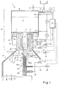
- a metering device 101 which includes a fluidized bed apparatus 1, into which powdery or granular solid is fed via a conveying device 21, which solidifies through fluidizing gas G, which flows through openings 11a in the base 11, to form a fluidized bed 2 becomes.
- the gas / solid mixture which behaves like a liquid can flow out via an outlet opening 3, it being possible for a nozzle device 28 to be arranged adjoining the outlet opening 3 if necessary.
- This nozzle device 28 comprises gas feeds 6, 5, which allow additional gassing of the gas / solid mixture and thus influence its homogeneity, but in particular allow time-constant metering of the escaping gas / solid flow.
- Signals from pressure sensors 12, 12 'and 12e are fed to, for example, a memory-programmed control or regulation 34, which controls the fluidization and the additional gassing via the control of the valves 13, 13a and 13b and / or the pressure above the fluidized bed 2 via a valve 33 and / or the supply of the solid in the fluidized bed 2 via the motor M.
- a memory-programmed control or regulation 34 which controls the fluidization and the additional gassing via the control of the valves 13, 13a and 13b and / or the pressure above the fluidized bed 2 via a valve 33 and / or the supply of the solid in the fluidized bed 2 via the motor M.
- the metering device 101 shown here serves as an example of a metering device with which a time-constant allocation of solid material is possible. Depending on the solids, the desired treatment and the desired dosing accuracy, other dosing devices will be selected.
- the gas / solid mixture emerges from the nozzle device 28 in the form of a jet 102, hereinafter referred to simply as a solid jet for the sake of simplicity, although - depending on the type of allocation or the method to be carried out, gas or liquid could be added.
- a nozzle 103 is arranged below the nozzle device 28 of the metering device 101 serving as an outlet.
- the nozzle 103 has two channels 104 and 104a, through which fluid can be discharged.
- At least one of the two channels preferably the one whose opening (s) 105 (for the type and number of the opening (s) see below, in particular FIGS. 4, 4a-4d and 7, 7a, 7b) closer to the metering device 101 lie, carries fluid, preferably gas, with which the solid jet 102 - controlled via an inlet valve 13 '- is applied. This results in an umbrella-like fanning out of the solid jet 102; depending on the amount or speed of the fluid, a solid veil 8 of a certain thickness is created.
- the solid jet 102 is acted upon by fluid in such a way that a velocity component v e of the fluid is directed in the opposite direction to the solid jet direction 7 and / or a velocity component v s of the fluid relative to this solid jet direction 7 is vertical.
- a velocity component v e of the fluid is directed in the opposite direction to the solid jet direction 7 and / or a velocity component v s of the fluid relative to this solid jet direction 7 is vertical.
- the concentration distribution will be substantially uniform over the entire screen-shaped, solid-filled area, but at least for partial areas that can be delimited by planes 4a, 4b, 4c which are perpendicular to the solid jet direction 7.
- the free nozzle end is tapered, possible interactions between solid particles and nozzle tip, and thus their abrasion, are reduced.
- Fluid, and then in particular gas, can also be discharged through the opening (s) 105a of the second channel 104a, with the result that the solid is fanned out more.
- treatment medium can also be applied, in particular sprayed, to the lower surface of the solid veil 8 via such a channel 104a.
- the upper surface of the solid veil can also be sprayed with treatment medium.
- nozzles 9 are provided on the housing 114, via which the solid veil 8 is acted upon in the most uniform manner possible.
- a plurality of nozzles 9 are preferably arranged around the jet direction 7, and a ring-shaped nozzle is also conceivable.
- the treatment medium is fed to the nozzles 9 via a feed line 15 provided with an inlet valve 16.
- the solid treated in this way is drawn off via a - purely schematically indicated - exhaust line 17, treatment medium and / or fluidizing fluid and the fluid causing the spatial distribution to be changed via a - also only schematically indicated - exhaust line 18. It is understood that possibly only one Discharge line may be provided.
- Valves 13 'and 23 in the feed lines 20 and 22 to the fluid-carrying channels 104 and 104a can optionally also be controlled via the controller 34 in accordance with a desired treatment sequence.
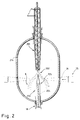
- FIG. 2 shows a metering device 201 in the form of a screw conveyor, via which solid in the form of a jet 202 is fed into a housing 214.
- the solid jet 202 is acted upon by fluid, in particular gas, from the nozzle 203, which here has only one fluid-carrying channel 204, so that an umbrella-like widening of the solid jet 202 is effected.
- the housing 214 has a particularly annular region 24, via which thermal radiation (heating coils 25 are indicated) reaches the interior of the housing 214 and the solid veil 8.
- a metering device such as the screw conveyor shown in FIG. 2 can then serve as a solids metering device if time-constant metering of the solids is not essential.
- Time-constant dosing which is possible, for example, by means of a dosing device described with reference to FIG. 1, is desired for processes which take place in short times and in which no backmixing should take place.
- FIG. 3 shows a nozzle 303 which, in accordance with the nozzle 103 shown in FIG. 1, has two fluid-carrying channels 304 and 304a, but in contrast to this is directed in the jet direction 7 of the solid jet 302 emerging from the metering device 301.
- the metering device 301 here is a fluidized bed apparatus. Fluidizing gas is supplied via a pneumatic line 19 (roughly corresponding to FIG. 1) and flows through openings 11a in the base 11, the solid material fed into the fluidized bed apparatus being fluidized and present in the fluidized bed 2 as a solid-fluid mixture. The solid-gas mixture flows out through the outlet opening 3 in the fluidized bed base 11 and, since the nozzle 303 is arranged in the center of the outlet opening 3, is present as a hollow jet 302 — likewise referred to as a solid jet.
- Fluid is discharged via openings 305, which are closer to the outlet opening 3, which serves to expand the solid jet 302. Fluid can then be discharged through openings 105a following in jet direction 7, which - as discussed with reference to FIG. 1 - either serves to further expand the solid jet 302, thus resulting in a wide, thin solid curtain 8, or else serves to discharge treatment medium, that on the lower surface of the umbrella-shaped Solid veil 8 applied, as sprayed or sprayed, can be.
- a further or even the only treatment medium can be provided via nozzle devices or - in the case of radiation treatment - via a specifically designed housing area or by the provision of corresponding devices, which may also be inside the housing can be arranged to be applied.
- nozzle 302 is arranged in the jet direction 7, as shown by way of example in FIG. 3, in which case - in order to reduce erosion from the solid particles moving in the fluidized bed 2 - a straight, central feed of the nozzle 303 may be preferable (indicated by dashed lines) the expansion of the solid jet and the formation of an umbrella-shaped solid veil 8 hardly influenced by the holder of the nozzle.
- FIGS. 4 a to 4 c each of which shows a section along A-A of FIG.
- FIGS. 4 a to 4 c are defined by spacers 25 between the nozzle holder 26 and the nozzle tip 27.
- openings 405 i which are designed in the form of tangential channels between the spacers 25 a.
- the fluid emerging therefrom - except for low exit velocities - is substantially radially expanded by the conically widening housing 414 Apply the solid jet and, if necessary, cause the resulting solid screen to rotate.
- the speed or quantity of the fluid emerging from the openings 405i must be controlled in such a way that there is no "perforation" of the solid screen by the fluid jets.
- FIG. 4b The arrangement shown in FIG. 4b with rod-shaped spacers 25b results in a uniform fluid supply over the entire circumference of the nozzle and the annular nozzle opening 405ii.
- a plurality of such spacers 25b can also be provided, distributed symmetrically, as a result of which the stability of the connection between the nozzle tip 27 and the nozzle holder 26 (FIG. 4) is improved.
- FIG. 4c shows a variant in which radially aligned spacers 25c are provided.
- fluid that flows from the openings 405iii lying between them will not flow out evenly over the circumference of the nozzle, as in the embodiment shown in FIG. 4b, for example.
- the free end of the nozzle 403 can also be designed as a baffle plate 47, as can be seen from FIG. 4d.
- the fluid-carrying channel 404a is designed as an annular channel, the inner wall of which serves as a support structure for the baffle plate 47.
- Lattice-like or rod-like spacers 48 between the outer and inner walls of the channel 404a enable an unimpeded flow of fluid.
- the fluid exits the annular opening 405iv uniformly on all sides.
- a rounded transition between the inner wall of the channel 404a and the baffle plate 47 improves the guidance of the fluid.
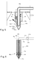
- FIG. 5 and also FIG. 6 show nozzles 503 and 603, in which the openings 505 and 605 are adjustable with regard to their cross section and / or direction.
- FIG. 5 shows a central nozzle holder 26a, which has openings 505i and over which two tubular diaphragm parts 29a and 29b are slidably arranged. These diaphragm parts 29a and 29b also have openings 505a and 505b, which are designed corresponding to the openings of the nozzle holder 26a, so that they are aligned with one another when the two diaphragm parts 29a and 29b are in the appropriate position.
- Adjustment devices 30 provided in a holder 38, which are shown here as a toothed rack 31 with a cooperating gear wheel 32, allow the diaphragm parts 29a and 29b to be displaced independently of one another, so that the direction of the resulting opening 505 of the nozzle 503 and thus also the direction of the gas flowing therefrom is adjustable and is given, for example, by the arrow 39 in the diaphragm position shown in FIG. A reduction in the opening cross section of the opening 505 of the nozzle 503 is also possible by adjusting the diaphragm parts 29a and 29b.
- FIG. 6 shows another possibility of how the opening cross section of the opening 605 can be adjusted on a nozzle 603 without the need for additional components, which are generally suitable for the cover device that covers the adjusting devices for the diaphragm system the process will be disruptive or represent additional wear parts.
- the nozzle 603 has three fluid-carrying channels 604, and 40a and 40b.
- the annular channel 604 guides the fluid that exits the annular opening 605 and expands the solid jet.
- a further annular channel 40a is arranged around this annular channel 604, the end faces of which are closed by an annular membrane 43a.
- a central channel 40b leads to the nozzle tip 27a and forms a bead-like counter ring, likewise closed by a ring membrane 43b, so that the opening 605 for the fluid supplied via the channel 604 is limited by the two ring membranes 43a and 43b.
- fluid is now supplied or drained via pneumatic (possibly also hydraulic) lines 41a and 41b, via valves 42a and 42b, then expand or contract the two ring membranes 43a and 43b, as a result of which the opening cross section of the opening 605 is reduced or enlarged.
- Such a method of operation is also possible with only one opening delimited on one side by a membrane and thus only one additional fluid-carrying channel.
- Fig. 7 shows very schematically a metering device 701 corresponding to Fig. 1, i.e. a fluidized bed apparatus 1 with a nozzle device 28 adjoining the outlet opening 3 for the time-constant metering of an outflowing solid jet.
- the nozzle 703 is here again arranged in the jet direction, specifically centrally in the nozzle device 28.
- the nozzle 703 has a porous region 37a, as a result of which there is a very large number of uniformly distributed, fine openings 705. This enables a particularly uniform, but only to a limited extent, a directed application of fluid to the solid jet.
- 7a and 7b show nozzles with a porous region 37b and 37c, the other arrangement of which allows the fluid to be directed a little differently.
- a dosing device 801 is indicated in FIG. 8, which can optionally be designed in accordance with that described in FIGS. 1 and 7, or else only represents an allotment device with a specially shaped discharge nozzle 28a (which, if applicable, the nozzle device 28 of FIG 7 corresponds).
- a nozzle 803 protrudes through this discharge nozzle 28a, the free end of which is designed to be enlarged like a stamp. If this nozzle 803 is moved in or against the solids jet direction 7, in accordance with arrow 44, the throughput of solids from the metering device is variable, yes, even interrupted if the dimensions are suitable.
- the nozzle 803 thus also serves as a flow valve here.
- a nozzle 803 designed in this way will cause a purely mechanical beam expansion solely by virtue of its shape. If necessary, such a nozzle shape alone can bring about a sufficiently good expansion of the solid jet (in an equivalent manner, this also applies to nozzles which are arranged against the jet direction 7) without the solid jet being subjected to fluid. Such a purely mechanical expansion of the solid jet can be sufficient for low-wear solids and - if necessary also for cost reasons - be advantageous.
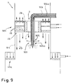
- FIG. 9 A device is shown in FIG. 9 which enables a further spatial expansion and spreading of the solid jet fed from a metering device.
- the dosing device 901 corresponds to the dosing device described in FIGS. 1 and 7, it thus comprises a fluidized bed apparatus 1 with a nozzle device 28 adjoining the outlet opening 3 for the time-constant dosing of an outflowing solid jet.
- the nozzle 903 is here again arranged in the jet direction, specifically centrally in the nozzle device 28.
- the configuration of the nozzle 903 essentially corresponds to that of FIG. 1 or FIG. 3.
- Two fluid-carrying channels 904 and 904a are provided, wherein fluid is discharged through the openings 905 of the first channel 904, which serves in the manner shown above for fanning out the solid jet. Via the opening (s) 905a of the second channel 904a, either fluid can be discharged to intensify the fanning out of the solid jet or treatment medium can also be sprayed out.
- a fluid supply device 45 is arranged above the fluid outlet openings 905 of the nozzle 903, wherein it surrounds the latter approximately concentrically.
- the outlet openings for the fluid are designed in the form of porous subregions 46, with a pore size increasing towards the housing wall. This makes it possible to set a specific speed profile, which on the one hand results in an even spatial distribution of the solid and on the other hand also prevents material build-up ("sticking") on the wall of the housing 914.
- Baffles could also be provided, which serve as flow straighteners for a fluid flowing out of the fluid supply device 46 instead of the partial areas 46 of different porosity.
- One or, if appropriate, further fluid supply devices 45a can be operated in the housing 914, which widens in the solid jet direction 7, whereby a double effect is achieved.
- the multistage fluid addition enables a uniform distribution of the solid over a large spatial area, the solid is then in the form of a weakly concentrated cloud, on the other hand, the shape of the housing 914 - corresponding to a diffuser - supports this spatial distribution.
Landscapes
- Chemical & Material Sciences (AREA)
- Organic Chemistry (AREA)
- Chemical Kinetics & Catalysis (AREA)
- Engineering & Computer Science (AREA)
- Combustion & Propulsion (AREA)
- Devices And Processes Conducted In The Presence Of Fluids And Solid Particles (AREA)
Applications Claiming Priority (2)
| Application Number | Priority Date | Filing Date | Title |
|---|---|---|---|
| CH2285/93 | 1993-07-29 | ||
| CH228593A CH692654A5 (de) | 1993-07-29 | 1993-07-29 | Vorrichtung und Verfahren zum Verändern der räumlichen Verteilung eines pulverförmigen Feststoffes. |
Publications (2)
| Publication Number | Publication Date |
|---|---|
| EP0636405A2 true EP0636405A2 (fr) | 1995-02-01 |
| EP0636405A3 EP0636405A3 (fr) | 1995-03-15 |
Family
ID=4230200
Family Applications (1)
| Application Number | Title | Priority Date | Filing Date |
|---|---|---|---|
| EP94110553A Ceased EP0636405A3 (fr) | 1993-07-29 | 1994-07-07 | Installation et procédé pour changer la distribution spatiale d'un solide pulvérulent. |
Country Status (2)
| Country | Link |
|---|---|
| EP (1) | EP0636405A3 (fr) |
| CH (1) | CH692654A5 (fr) |
Cited By (3)
| Publication number | Priority date | Publication date | Assignee | Title |
|---|---|---|---|---|
| DE102004043411B3 (de) * | 2004-09-02 | 2006-05-04 | Weitmann & Konrad Gmbh & Co Kg | Vorrichtung und Verfahren zum Erzeugen eines Puder-Luft-Gemisches |
| CN102762753A (zh) * | 2009-09-03 | 2012-10-31 | 纳幕尔杜邦公司 | 在四氯化钛制造中利用反馈响应和前馈响应的组合来控制载钛材料流量 |
| CN107499973A (zh) * | 2017-08-03 | 2017-12-22 | 山西潞安煤基合成油有限公司 | 锅炉灰库蒸汽除尘装置 |
Family Cites Families (6)
| Publication number | Priority date | Publication date | Assignee | Title |
|---|---|---|---|---|
| DE478715C (de) * | 1929-07-03 | Arno Frohberg | Anordnung von Mundstuecken zum Einfuehren eines Druckmittels in einen Schuettgutstrom | |
| US2952622A (en) * | 1957-12-12 | 1960-09-13 | Sun Oil Co | Process and apparatus for contacting hydrocarbons with a granular catalyst |
| GB965968A (en) * | 1962-06-25 | 1964-08-06 | Nat Dairy Prod Corp | Powder agglomerating method and apparatus |
| DE2554032C2 (de) * | 1975-12-02 | 1985-11-28 | Babcock-BSH AG vormals Büttner-Schilde-Haas AG, 4150 Krefeld | Vorrichtung zum Inberührungbringen einer Flüssigkeit mit einem pulverförmigen Feststoff |
| US4210315A (en) * | 1977-05-16 | 1980-07-01 | Outokumpu Oy | Means for producing a suspension of a powdery substance and a reaction gas |
| FR2628014B1 (fr) * | 1988-03-07 | 1992-04-24 | Total France | Procede et dispositif pour enrober des particules solides d'un film continu d'une matiere protectrice |
-
1993
- 1993-07-29 CH CH228593A patent/CH692654A5/de not_active IP Right Cessation
-
1994
- 1994-07-07 EP EP94110553A patent/EP0636405A3/fr not_active Ceased
Cited By (5)
| Publication number | Priority date | Publication date | Assignee | Title |
|---|---|---|---|---|
| DE102004043411B3 (de) * | 2004-09-02 | 2006-05-04 | Weitmann & Konrad Gmbh & Co Kg | Vorrichtung und Verfahren zum Erzeugen eines Puder-Luft-Gemisches |
| US7607451B2 (en) | 2004-09-02 | 2009-10-27 | Weitmann & Konrad Gmbh & Co. Kg | Device and method for the production of a powder-air mixture |
| CN102762753A (zh) * | 2009-09-03 | 2012-10-31 | 纳幕尔杜邦公司 | 在四氯化钛制造中利用反馈响应和前馈响应的组合来控制载钛材料流量 |
| CN102762753B (zh) * | 2009-09-03 | 2014-03-05 | 纳幕尔杜邦公司 | 在四氯化钛制造中利用反馈响应和前馈响应的组合来控制载钛材料流量 |
| CN107499973A (zh) * | 2017-08-03 | 2017-12-22 | 山西潞安煤基合成油有限公司 | 锅炉灰库蒸汽除尘装置 |
Also Published As
| Publication number | Publication date |
|---|---|
| EP0636405A3 (fr) | 1995-03-15 |
| CH692654A5 (de) | 2002-09-13 |
Similar Documents
| Publication | Publication Date | Title |
|---|---|---|
| EP2981352B1 (fr) | Étoile rotative de sèchage pour traiter des particules solides | |
| DE3072202T2 (de) | Fluessigkeitsbehandlungsanlage. | |
| DE2504932C2 (de) | Verfahren zur Verarbeitung eines feststoffbeladenen Fluids und Fluiddüse zur Durchführung des Verfahrens | |
| EP2707127B1 (fr) | Dispositif de traitement continu de matières solides dans un appareil à lit fluidisé | |
| EP0028025A1 (fr) | Procédé et dispositif pour la production de gouttes de liquide microfines | |
| WO2016066427A2 (fr) | Procédé de nettoyage, unité de commande et dispositif de raccordement | |
| DE4118433C2 (de) | Fließbettapparatur zum Behandeln partikelförmigen Gutes | |
| DE2413213C3 (de) | Vorrichtung zur gleichmäßigen Verteilung von Flüssigkeit zwischen Abschnitten unterschiedlichen Durchmessers innerhalb einer Fraktionierkolonne | |
| DE3110173C2 (de) | Gas-Flüssigkeitskontaktvorrichtung | |
| EP0636405A2 (fr) | Installation et procédé pour changer la distribution spatiale d'un solide pulvérulent | |
| DE2409544A1 (de) | Vorrichtung zum verspruehen eines fliessfaehigen mediums | |
| WO1989007977A1 (fr) | Installation a lit fluidise, notamment pour granuler une substance pulverulente | |
| DE1442613C3 (de) | Vorrichtung zum Behandeln von Fest stoffteilchen, insbesondere Kohleteilchen, in einem Fließbett | |
| DE69620736T2 (de) | WIRBELBETT mit gleichmässiger Wärmeverteilung und mehrportiger Dute | |
| DE69813207T2 (de) | Pulsierende fliessbettschicht | |
| DE1451265B2 (de) | Verfahren zum Betrieb von mit beweglichen Masseteilchen als Wärmeträger arbeitenden Apparaten, vorzugsweise Wärmetauschern, sowie Einrichtung zur Durchführung des Verfahrens | |
| EP2841555B1 (fr) | Dispositif d'évaporation du moût | |
| DE68911927T2 (de) | Spritztrocknungsvorrichtung. | |
| DE3419170C1 (de) | Zuführungseinrichtung für eine Vorrichtung zur gleichmäßigen Flüssigkeitsverteilung bei Fallstromververdampfern | |
| DE2616828C3 (de) | Wirbelschichtbehälter | |
| DE19700029B4 (de) | Wirbelschichtapparat | |
| DE3883240T2 (de) | Verfahren zum erzeugen eines gleichmässigen flusses in einem langgestreckten fliessbettofen. | |
| DE1126358B (de) | Vorrichtung zur gleichmaessigen Verteilung der Fluessigkeit auf die Heizrohre eines Gleich- und Fallstromverdampfers | |
| DE2155898C3 (de) | Gasverteiler für eine Wirbelschicht-Vorrichtung | |
| DE3829215A1 (de) | Reaktor zur durchfuehrung katalytischer gasreaktionen mit einem druckfesten mantel und je einem kugelboden am stirnseitigen aussenrand |
Legal Events
| Date | Code | Title | Description |
|---|---|---|---|
| PUAI | Public reference made under article 153(3) epc to a published international application that has entered the european phase |
Free format text: ORIGINAL CODE: 0009012 |
|
| PUAL | Search report despatched |
Free format text: ORIGINAL CODE: 0009013 |
|
| AK | Designated contracting states |
Kind code of ref document: A2 Designated state(s): AT BE CH DE DK ES FR GB GR IE IT LI LU NL PT SE |
|
| RAX | Requested extension states of the european patent have changed |
Free format text: SI PAYMENT 940707 |
|
| AK | Designated contracting states |
Kind code of ref document: A3 Designated state(s): AT BE CH DE DK ES FR GB GR IE IT LI LU NL PT SE |
|
| 17P | Request for examination filed |
Effective date: 19950202 |
|
| 17Q | First examination report despatched |
Effective date: 19970206 |
|
| STAA | Information on the status of an ep patent application or granted ep patent |
Free format text: STATUS: THE APPLICATION HAS BEEN REFUSED |
|
| 18R | Application refused |
Effective date: 19991106 |