EP0636410A1 - Corps céramique structuré en nid d'abeille et catalyseur à base de celui-ci - Google Patents
Corps céramique structuré en nid d'abeille et catalyseur à base de celui-ci Download PDFInfo
- Publication number
- EP0636410A1 EP0636410A1 EP94302077A EP94302077A EP0636410A1 EP 0636410 A1 EP0636410 A1 EP 0636410A1 EP 94302077 A EP94302077 A EP 94302077A EP 94302077 A EP94302077 A EP 94302077A EP 0636410 A1 EP0636410 A1 EP 0636410A1
- Authority
- EP
- European Patent Office
- Prior art keywords
- structural body
- honeycomb structural
- partition walls
- catalyst
- ceramic honeycomb
- Prior art date
- Legal status (The legal status is an assumption and is not a legal conclusion. Google has not performed a legal analysis and makes no representation as to the accuracy of the status listed.)
- Granted
Links
Images














Classifications
-
- B—PERFORMING OPERATIONS; TRANSPORTING
- B01—PHYSICAL OR CHEMICAL PROCESSES OR APPARATUS IN GENERAL
- B01J—CHEMICAL OR PHYSICAL PROCESSES, e.g. CATALYSIS OR COLLOID CHEMISTRY; THEIR RELEVANT APPARATUS
- B01J35/00—Catalysts, in general, characterised by their form or physical properties
- B01J35/50—Catalysts, in general, characterised by their form or physical properties characterised by their shape or configuration
- B01J35/56—Foraminous structures having flow-through passages or channels, e.g. grids or three-dimensional [3D] monoliths
- B01J35/57—Honeycombs
-
- B—PERFORMING OPERATIONS; TRANSPORTING
- B01—PHYSICAL OR CHEMICAL PROCESSES OR APPARATUS IN GENERAL
- B01J—CHEMICAL OR PHYSICAL PROCESSES, e.g. CATALYSIS OR COLLOID CHEMISTRY; THEIR RELEVANT APPARATUS
- B01J21/00—Catalysts comprising the elements, oxides, or hydroxides of magnesium, boron, aluminium, carbon, silicon, titanium, zirconium, or hafnium
- B01J21/16—Clays or other mineral silicates
-
- B—PERFORMING OPERATIONS; TRANSPORTING
- B01—PHYSICAL OR CHEMICAL PROCESSES OR APPARATUS IN GENERAL
- B01J—CHEMICAL OR PHYSICAL PROCESSES, e.g. CATALYSIS OR COLLOID CHEMISTRY; THEIR RELEVANT APPARATUS
- B01J35/00—Catalysts, in general, characterised by their form or physical properties
- B01J35/30—Catalysts, in general, characterised by their form or physical properties characterised by their physical properties
- B01J35/31—Density
-
- B—PERFORMING OPERATIONS; TRANSPORTING
- B01—PHYSICAL OR CHEMICAL PROCESSES OR APPARATUS IN GENERAL
- B01J—CHEMICAL OR PHYSICAL PROCESSES, e.g. CATALYSIS OR COLLOID CHEMISTRY; THEIR RELEVANT APPARATUS
- B01J35/00—Catalysts, in general, characterised by their form or physical properties
- B01J35/30—Catalysts, in general, characterised by their form or physical properties characterised by their physical properties
- B01J35/34—Mechanical properties
- B01J35/36—Mechanical strength
-
- B—PERFORMING OPERATIONS; TRANSPORTING
- B01—PHYSICAL OR CHEMICAL PROCESSES OR APPARATUS IN GENERAL
- B01J—CHEMICAL OR PHYSICAL PROCESSES, e.g. CATALYSIS OR COLLOID CHEMISTRY; THEIR RELEVANT APPARATUS
- B01J35/00—Catalysts, in general, characterised by their form or physical properties
- B01J35/40—Catalysts, in general, characterised by their form or physical properties characterised by dimensions, e.g. grain size
-
- B—PERFORMING OPERATIONS; TRANSPORTING
- B01—PHYSICAL OR CHEMICAL PROCESSES OR APPARATUS IN GENERAL
- B01J—CHEMICAL OR PHYSICAL PROCESSES, e.g. CATALYSIS OR COLLOID CHEMISTRY; THEIR RELEVANT APPARATUS
- B01J37/00—Processes, in general, for preparing catalysts; Processes, in general, for activation of catalysts
- B01J37/0009—Use of binding agents; Moulding; Pressing; Powdering; Granulating; Addition of materials ameliorating the mechanical properties of the product catalyst
-
- C—CHEMISTRY; METALLURGY
- C04—CEMENTS; CONCRETE; ARTIFICIAL STONE; CERAMICS; REFRACTORIES
- C04B—LIME, MAGNESIA; SLAG; CEMENTS; COMPOSITIONS THEREOF, e.g. MORTARS, CONCRETE OR LIKE BUILDING MATERIALS; ARTIFICIAL STONE; CERAMICS; REFRACTORIES; TREATMENT OF NATURAL STONE
- C04B38/00—Porous mortars, concrete, artificial stone or ceramic ware; Preparation thereof
- C04B38/0006—Honeycomb structures
-
- F—MECHANICAL ENGINEERING; LIGHTING; HEATING; WEAPONS; BLASTING
- F01—MACHINES OR ENGINES IN GENERAL; ENGINE PLANTS IN GENERAL; STEAM ENGINES
- F01N—GAS-FLOW SILENCERS OR EXHAUST APPARATUS FOR MACHINES OR ENGINES IN GENERAL; GAS-FLOW SILENCERS OR EXHAUST APPARATUS FOR INTERNAL-COMBUSTION ENGINES
- F01N3/00—Exhaust or silencing apparatus having means for purifying, rendering innocuous, or otherwise treating exhaust
- F01N3/08—Exhaust or silencing apparatus having means for purifying, rendering innocuous, or otherwise treating exhaust for rendering innocuous
- F01N3/10—Exhaust or silencing apparatus having means for purifying, rendering innocuous, or otherwise treating exhaust for rendering innocuous by thermal or catalytic conversion of noxious components of exhaust
- F01N3/24—Exhaust or silencing apparatus having means for purifying, rendering innocuous, or otherwise treating exhaust for rendering innocuous by thermal or catalytic conversion of noxious components of exhaust characterised by constructional aspects of converting apparatus
- F01N3/28—Construction of catalytic reactors
- F01N3/2803—Construction of catalytic reactors characterised by structure, by material or by manufacturing of catalyst support
- F01N3/2825—Ceramics
- F01N3/2828—Ceramic multi-channel monoliths, e.g. honeycombs
-
- C—CHEMISTRY; METALLURGY
- C04—CEMENTS; CONCRETE; ARTIFICIAL STONE; CERAMICS; REFRACTORIES
- C04B—LIME, MAGNESIA; SLAG; CEMENTS; COMPOSITIONS THEREOF, e.g. MORTARS, CONCRETE OR LIKE BUILDING MATERIALS; ARTIFICIAL STONE; CERAMICS; REFRACTORIES; TREATMENT OF NATURAL STONE
- C04B2111/00—Mortars, concrete or artificial stone or mixtures to prepare them, characterised by specific function, property or use
- C04B2111/00474—Uses not provided for elsewhere in C04B2111/00
- C04B2111/0081—Uses not provided for elsewhere in C04B2111/00 as catalysts or catalyst carriers
-
- F—MECHANICAL ENGINEERING; LIGHTING; HEATING; WEAPONS; BLASTING
- F01—MACHINES OR ENGINES IN GENERAL; ENGINE PLANTS IN GENERAL; STEAM ENGINES
- F01N—GAS-FLOW SILENCERS OR EXHAUST APPARATUS FOR MACHINES OR ENGINES IN GENERAL; GAS-FLOW SILENCERS OR EXHAUST APPARATUS FOR INTERNAL-COMBUSTION ENGINES
- F01N2330/00—Structure of catalyst support or particle filter
- F01N2330/02—Metallic plates or honeycombs, e.g. superposed or rolled-up corrugated or otherwise deformed sheet metal
- F01N2330/04—Methods of manufacturing
-
- F—MECHANICAL ENGINEERING; LIGHTING; HEATING; WEAPONS; BLASTING
- F01—MACHINES OR ENGINES IN GENERAL; ENGINE PLANTS IN GENERAL; STEAM ENGINES
- F01N—GAS-FLOW SILENCERS OR EXHAUST APPARATUS FOR MACHINES OR ENGINES IN GENERAL; GAS-FLOW SILENCERS OR EXHAUST APPARATUS FOR INTERNAL-COMBUSTION ENGINES
- F01N2330/00—Structure of catalyst support or particle filter
- F01N2330/06—Ceramic, e.g. monoliths
Definitions
- the present invention relates to a ceramic honeycomb structural body suitable for a catalyst carrier, wherein a number of flow channels having a polygonal cell-like cross-section and extending longitudinally through the honeycomb structural body are defined by a peripheral wall and partition walls arranged inside of the peripheral wall.
- the present invention also relates to a ceramic honeycomb catalyst comprising such a honeycomb structural body and a catalytic substance carried thereon.
- the ceramic honeycomb structural body having the above-mentioned arrangement is widely used, for example, as a catalyst carrier in an exhaust gas cleaning system for automobiles.
- the ceramic honeycomb structural body as the catalyst carrier has become widespread due to a low pressure loss during passage of the exhaust gas as a result of a high open frontal area, and an excellent exhaust gas clarifying performance.
- an advanced ceramic honeycomb structural body which has been put into practical use has, for example, a partition wall thickness of 0.170 mm and a cell density of 60 cells per 1 cm2.
- the thin-walled ceramic honeycomb structural body serves on one hand to increase the open frontal area and thereby decrease the pressure loss and reduce the structure weight, and on the other hand to decrease the heat capacity of the catalyst and enhance the temperature elevation speed of the catalyst.
- a large geometric surface area of the honeycomb structural body can be obtained so that it is also possible to realize a compact structure.
- the thin-walled ceramic honeycomb structure requires a careful handling because it is generally difficult to achieve a predetermined minimum guarantee value for the isostatic destruction strength as one index of the structural strength.
- a typical canning method is to hold the honeycomb structural body from the outer peripheral surface thereof, though there may be instances wherein the honeycomb structural body is held either solely in the flow passage direction, or from the outer peripheral surface and also in the flow passage direction. Therefore, it is generally considered necessary for the above-mentioned minimum guarantee value to be no less than 5 kgf/cm2, preferably no less than 10 kgf/cm2 in term of the isostatic destruction strength.
- Another object of the present invention is to provide an improved ceramic honeycomb catalyst having a reduced heat capacity provided by a thin-walled ceramic honeycomb structural body with a sufficient isostatic destruction strength despite the thin partition walls.
- a ceramic honeycomb structural body comprising an outer peripheral wall having a thickness of at least 0.1 mm, preferably 0.15 mm or more, and partition walls arranged inside of the peripheral wall and having a thickness (t) within a range of 0.050 mm and 0.150 mm, a number of flow channels being defined by the peripheral wall and the partition walls and arranged adjacent to each other with the partition walls between neighboring flow passages, the flow passages having a polygonal cell-like cross-section and extending longitudinally through the honeycomb structural body, the honeycomb structural body comprising a ceramic material having a true specific gravity and a porosity and satisfying at least one of the following formulae (1) and (2): 0.65 ⁇ OFA ⁇ -0.58 ⁇ t + 0.98 (1) k ⁇ ⁇ 1 - (-0.58 ⁇ t + 0.98) ⁇ ⁇ G ⁇ k ⁇ 0.35 (2) wherein OFA and G are an open frontal area and a bulk density of the honeycomb structural body, respectively
- the present invention also provides an improved ceramic honeycomb catalyst comprising a catalyst carrier formed of a ceramic honeycomb structural body, and a catalytic substance carried by the honeycomb structural body, wherein the ceramic honeycomb structural body includes all the above-mentioned novel features of the present invention.
- the catalyst according to the invention can have a heat capacity of no more than 450 kJ/K per unit volume of 1 m3 of the catalyst, preferably no more than 410 kJ/K per 1 m3.
- the "A-axis compressive strength”, the "B-axis compressive strength” and the “isostatic strength” as used herein are indices of the compressive strength all defined in the JASO standard M505-87, an automobile standard issued by Corporation of Automobile Technology Association.
- the A-axis compressive strength refers to a destruction strength when a compressive load is applied in the flow passage direction of the honeycomb structure, i.e., in the direction perpendicular to the cross-section of the honeycomb structure.
- the B-axis compressive strength is defined as a destruction strength when a compressive load is applied in the direction parallel to the cross-section of the honeycomb structure and perpendicular to the partition walls.
- the isostatic strength refers to a compressive destruction strength when an isostatic, namely isotropic hydrostatic load is applied to the honeycomb structure, and is represented by a pressure value when the destruction occurs.
- the A-axis compressive strength is not significantly affected by disorders of the honeycomb structure, such as deformation degree of the partition wall and the like, but has a strong correlation with the material strength since the compressive load is applied in the flow passage direction.
- the B-axis compressive strength depends on the material strength, it is more strongly affected by disorders of the honeycomb structure such as a deformation degree of the partition wall. This applies to the isostatic strength as well, so that any one of the isostatic strength and the B-axis compressive strength serves as an index of the strength characteristic of the structure.
- the B-axis compressive strength is measured in a state in which there is no peripheral wall, and is therefore free from any influence of the peripheral wall structure.
- the peripheral wall exhibits a function as an outer shell to protect the inner honeycomb structure from an external pressure and to withstand the load during the canning at its outer peripheral surface.
- the peripheral wall bears an important role in this respect, because its destruction in many cases results in that the partition walls adjacent to the peripheral wall are acted by an abnormal load to start a chain of local destructions.
- the peripheral wall thickness it is preferable for the peripheral wall thickness to be no less than 0.15 mm.
- the A-axis compressive strength and the B-axis compressive strength are basic indices of the strength characteristic of the honeycomb structure, in that the A-axis compressive strength mainly indicates the influence on the part of the material strength and the B-axis compressive strength indicates the influence on the part of the honeycomb structure.
- the isostatic strength indicates the practical structural strength characteristic and is expressed as a result of mutual interrelation of the influences of the material, the honeycomb structure, and the peripheral wall structure represented by the peripheral wall thickness.
- the partition walls of the ceramic honeycomb structural body as the catalyst carrier for the ceramic honeycomb catalyst are constituted as the thin walls as compared with those already known in the prior art. It is therefore possible not only to increase the open frontal area and reduce the pressure loss, but also to reduce the heat capacity of the honeycomb structure as the catalyst carrier and hence that of the catalyst itself. It is of course that the smaller the heat capacity of the catalyst is, the faster the catalyst temperature elevates in the cold start state, thereby allowing the catalyst to be activated earlier so as to achieve an improved exhaust gas clarification performance.
- the above-mentioned predetermined conditions as expressed by the formulae (1) and/or (2) are satisfied between the thickness of the partition walls and the open frontal area and/or bulk density of the honeycomb structure, so that it is possible to realize practically satisfactory compressive strength characteristics of the honeycomb structural body notwithstanding the thin-walled constitution.
- the constitution of the ceramic honeycomb structural body having the above-mentioned basic features according to the present invention is particularly advantageous from practical view point, when the thickness t of the partition walls is no more than 0.124 mm, when the open frontal area OFA is no less than 0.70 or when the bulk density G no more than k ⁇ 0.30, due to the following reasons. Namely, when the honeycomb structure having the wall thickness t of no more than 0.124 mm is used as the catalyst carrier, a particularly distinguished exhaust gas clarification performance can be achieved while realizing a practically satisfactory compressive strength characteristics.
- the open frontal area of the honeycomb structure is no less than 0.70 on the lower limit side or the bulk density G of the honeycomb structure is no more than k ⁇ 0.30 on the upper limit side, then it becomes possible to realize the satisfactory compressive strength characteristics while realizing an excellent pressure loss characteristic and the distinguished exhaust gas clarification performance. Further, since the weight of the honeycomb structural body is reduced, when it is used as the catalyst carrier in exhaust gas clarification systems for automobiles, it is possible to reduce the vehicle body weight of the automobile and hence improve the fuel consumption characteristic.
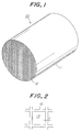
- a ceramic honeycomb structural body according to one embodiment of the present invention, which is denoted as a whole by reference numeral 10.
- the honeycomb structural body 10 is provided with a peripheral wall 11 and partition walls 12 arranged inside thereof.
- the partition walls 12 define in the honeycomb structural body 10 a number of flow passages 13 in the form of cells of a polygonal cross-section, e.g., a triangular, square or hexagonal cross-section.
- These flow passages 13 extend longitudinally through the honeycomb structural body 10, for passing therethrough a fluid, such as an exhaust gas of an internal combustion engine.
- the honeycomb structural body 10 may be round or circular in a cross-section perpendicular to the flow passage direction, as shown in Fig. 1.
- the honeycomb structural body 10 may have a different cross-sectional shape, e.g., an oval cross-section with elongated circular or elliptic contour, or other non-circular cross-section. Honeycomb structural bodies with such cross-sectional shapes, per se, are known and practically used. Moreover, the honeycomb structural body 10 has a longitudinal axis extending in the direction of the flow passages 13, which may be either straight or bent in a conventional manner known, per se.
- the honeycomb structural body 10 can be suitably used, e.g., as a catalyst carrier in exhaust gas clarification systems for automobiles.
- the honeycomb structural body 10 may be an integrally extruded body consisting essentially of cordierite, mullite, alumina, silicon carbide, silicon nitride or zirconia.
- the honeycomb structural body 10 is an integrally extruded body consisting essentially of cordierite and having flow channels 13 of square cross-section.
- the surface of the partition walls 12 is coated initially by a base material, such as ⁇ -alumina or the like, by an amount of no less than 100 g/l with reference to a catalyst volume.
- a catalytic substance consisting essentially of at least one of noble metals among Pt, Rh and Pd is carried on the surface of the base material, by an amount of no less than 2 g/l with reference to the catalyst volume.
- the ceramic honeycomb catalyst comprising the honeycomb structural body 10 which has been coated with the base material and the catalytic substance, as described above, has a heat capacity which is no more than 450 kJ/K, preferably no more than 410 kJ/K, per 1 m3 of the catalyst.
- the ceramic honeycomb structural body 10 has an A-axis compressive strength which is no less than 50 kgf/cm2, and a B-axis compressive strength which is no less than 5 kgf/cm2, preferably no less than 10 kgf/cm2.
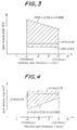
- the thickness of the peripheral wall 11 of the honeycomb structural body 10 is at least 0.1 mm, and the thickness t (Fig. 2) of the partition walls 12 is within a range between 0.050 mm and 0.150 mm.
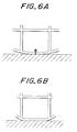
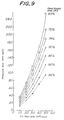
- the open frontal area OFA and the bulk density G of the honeycomb structural body 10 satisfy the following formulae (1) and (2), respectively: 0.65 ⁇ OFA ⁇ -0.58 ⁇ t + 0.98 (1) k ⁇ ⁇ 1 - (-0.58 ⁇ t + 0.98) ⁇ ⁇ G ⁇ k ⁇ 0.35 (2) where k is a factor representing the true specific gravity of the ceramic material forming the honeycomb structural body 10, multiplied by (1 - material porosity).
- the open frontal area OFA and the bulk density G of the honeycomb structural body 10 have a complementary relationship with each other so that, if either one of them has been determined, the other can be determined by itself when the true specific gravity and the porosity of the material are known.
- the present invention is to define the particular relationships between the partition wall thickness t and the the open frontal area OFA and between the partition wall thickness t and the bulk density G as shown in Figs. 3 and 4, respectively, wherein the formulae (1) and (2) are satisfied in the hatched regions.
- the upper limit value (-0.58 ⁇ t + 0.98) of the open frontal area OFA in the formula (1) is an approximate expression based on a result of investigations as shown in Fig. 5 in which the relationship between the open frontal area and the local deformations of the peripheral walls of various samples was investigated with the partition wall thickness t as the parameter, and the acceptability of these samples was judged according to the deformation degree.
- honeycomb structural bodies immediately after they have been extruded are conveyed to a subsequent step while being temporarily supported on a pedestal with their outer peripheral surfaces in abutment with a substantially horizontal supporting surface of the pedestal, as shown in Fig. 6A.
- the honeycomb structural body is still soft and may thus be subjected to a local deformation at the peripheral wall, as shown in Fig. 6B.
- a local deformation at the peripheral wall of the honeycomb structural body deviated contact of the honeycomb structure may occur during the canning, or the partition walls in the vicinity of the locally deformed region of the peripheral wall may undergo a successive deformation, thereby enhancing the probability of decrease in the isostatic strength and/or breakage of the honeycomb structure.
- the acceptability of the honeycomb structural body has been judged taking into account the deformation degree of the peripheral wall in relation to the open frontal area OFA of the honeycomb structure.
- an increase in the open frontal area OFA results in a decreased cell density, a decreased number of the partition walls forming the honeycomb structure and an increased intervals (cell pitch) of the partition walls supporting the circumferential wall.
- the relationship between the open frontal area OFA and the partition wall interval in the honeycomb structure is shown in Fig. 7. It can be clearly appreciated from Fig. 7 that, for any partition wall thickness, the partition wall interval rapidly increases at a certain open frontal area. Further investigations have been conducted on the relationship between the open frontal area OFA and the partition wall thickness t.
- the peripheral wall supported between the partition walls tends to deflect when the open frontal area OFA exceeds -0.58 ⁇ t + 0.98. It has been also confirmed that such deflection of the peripheral wall enhances the tendency of the local deformation of the peripheral wall and successive deformation of adjacent partition walls supporting the peripheral wall, thereby significantly decreasing the isostatic strength of the honeycomb structural body. If the partition walls and the peripheral walls have ideally accurate shapes without deformations, application of an isostatic load causes a compressive stress field to prevail in the honeycomb structure. However, occurrence of the local deformations may give rise to generation of tensile stresses at the deformed regions, and the isostatic strength is then governed by the tensile stress and caused to rapidly decrease.
- Fig. 8 shows a measuring system 20 used for the measurement of the pressure loss characteristic of the honeycomb structural body.
- the measuring system 20 includes an air blower 21, a flow straightening section 22 and a measuring section 23.
- Measurement with such a measuring system 20 has been carried out by arranging within the measuring section 23 an object whose pressure loss is to be measured, i.e., a honeycomb structural body 24, operating the blower 21 so that pressurized air is fed through the flow straightening section 22 and passed through the flow channels of the honeycomb structural body 24, and measuring the pressure loss across the honeycomb structural body 24, i.e., the pressure difference between the upstream and downstream sides of the honeycomb structural body 24, by means of a manometer 25 which is in connection with the measuring section 23.
- Measurement of the pressure loss characteristic by means of the measuring system 20 has been carried out with respect to a series of ceramic honeycomb structural bodies each having a constant size (cross-section and volume) and a different open frontal area, by changing the air flow rate.
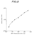
- FIG. 11 shows a testing apparatus 30 used for measuring the output of an actual internal combustion engine 31, which is comprised of a 6-cylinder gasoline engine having a displacement of 3000 cc, and is followed by an exhaust manifold 32 having a length of 50 cm.
- a converter 33 equipped with a honeycomb structural body (measurement object), is arranged on the immediate downstream side of the exhaust manifold 32.
- An underfloor converter 34 having a volume of 1700 cc and a muffler 35 are connected on the downstream side of the converter 33.
- a dynamometers 36 is connected to the output shaft of the engine 31.
- the engine output at the maximum output state of the engine 31 was measured by the dynamometer 36.
- the measurement was conducted with respect to a group of converters 33 on the immediate downstream side of the exhaust manifold 32, which were equipped with respective catalyst carriers constituted by ceramic honeycomb structural bodies having a constant size (volume 1700 cc) and different open frontal area.
- the result of such measurement is shown in Fig. 12 from which it can be appreciated that a decremental tendency of the engine output with decrease in the open frontal area of the ceramic honeycomb structural body becomes remarkable at an open frontal area of less than 70 %, particularly less than 65 %.
- Fig. 13A shows a diagram of the vehicle speed pattern of the LA-4 mode
- Fig. 13B shows the detailed vehicle speed pattern during the initial 505 seconds in the LA-4 mode.
- a test vehicle with a 6-cylinder gasoline engine having a displacement of 2500 cc was used to perform the exhaust gas measurement in an operational state in accordance with the vehicle speed pattern of the LA-4 mode, with respect to a series of catalytic converters sequentially connected on the immediate downstream side of the exhaust manifold of the exhaust gas system.
- These converters include respective ceramic honeycomb catalyst carriers each being of same size or volume and cell density, i.e., 1200 cc and 60 cells/cm2, and a different partition wall thickness.
- HC hydrocarbon
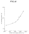
- Fig. 15 shows the discharge amount of hydrocarbon during the initial 505 seconds in the LA-4 mode, the data of which has been obtained with respect to the same series of converters as mentioned above. It can be appreciated from Fig. 15 that a reduced partition wall thickness results in a decreased hydrocarbon emission amount, and such a decremental tendency becomes remarkable at a partition wall thickness of no more than 0.124 mm.
- the performance of the exhaust gas clarification system for automobiles in the cold start state is primarily determined by the quality of the temperature elevation characteristic of the catalyst carrier itself, and the clarification performance can be improved by a reduced bulk density of the catalyst carrier, hence by a reduced heat capacity of the catalyst.
- the temperature of the catalyst carrier during the initial 505 seconds in the LA-4 mode was measured using a test vehicle with a 6-cylinder gasoline engine having a displacement of 2500 cc, with respect to a series of catalytic converters sequentially connected on the immediate downstream side of the exhaust manifold of the exhaust gas system.
- each converter includes a ceramic honeycomb catalyst carrier of same size or volume and cell density, i.e., 1200 cc and 60 cells/cm2, and a different partition wall thickness.
- the temperature of each catalyst carrier was measured at a central portion of the carrier, which is spaced 15 mm from the exhaust gas inlet side. The data obtained by such measurement is shown in Fig. 18 from which it can be appreciated that a reduced partition wall thickness and hence a reduced bulk density of the catalyst carrier results in improvement in the temperature elevation characteristic of the carrier.
- metal honeycomb catalyst has a relatively low temperature elevation rate than ceramic honeycomb catalyst. This is considered to result from the fact that metal has a higher heat conductivity than ceramics and thus provides a higher amount of heat dissipation during the temperature elevation process than ceramics.
- the amounts of various emission components (NOx, CO, HC) emitted during the initial 505 seconds in the LA-4 mode were measured using a test vehicle with a 6-cylinder gasoline engine having a displacement of 2500 cc, with respect to a series of honeycomb catalytic converters sequentially connected on the immediate downstream side of the exhaust manifold of the exhaust gas system.
- These converters were equipped with ceramic honeycomb catalyst carriers and a metal honeycomb catalyst carrier, respectively.
- the data obtained by such measurement is shown by the bar graph in Fig. 19 from which it can be appreciated that the ceramic honeycomb catalyst carriers are superior in the exhaust gas clarification performance than the metal honeycomb catalyst carrier.
- the ceramic honeycomb structural body 10 according to the present invention has an A-axis compressive strength of no less than 50 kgf/cm2 and a B-axis compressive strength of no less than 5 kgf/cm2.
- the inventors conducted thorough investigations and experiments, aiming at improvement in the compressive strength characteristics of the ceramic honeycomb structural body. As a result, it has been confirmed that deformation or defects which may occur in the partition walls during the production stage of the honeycomb structural body significantly causes the compressive strength to decrease.
- the inventors further reached a recognition that, in order to realize an excellent compressive strength characteristics notwithstanding a thin-walled structure of the ceramic honeycomb structural body, it is of particular importance to maintain the degree of the deformation of the partition walls and discontinuity or the like defects within quantitatively predetermined ranges, respectively.
- a bend deformation of the partition walls as one mode of possible deformation thereof.
- bend deformation occurs, e.g., at the inside of a ceramic honeycomb structural body, though the bend deformation tends to occur more frequently at a region of a partition wall in the vicinity of its junction to the peripheral wall.
- the bend deformation can be recognized, e.g., as a bend or curvature of the partition walls by observing the honeycomb structural body from the flow passage direction.
- the center line of the unit partition wall can be defined as a line which passes through centers of circles inscribing both sides of that partition wall. Between any two pints on such center line which are spaced from each other by a linear distance L A , the center line has an actual length L B which is always greater than the distance L A when the partition wall has been subjected to the bend deformation.
- the degree of the bend deformation can be expressed in terms of the length ratio L B /L A as exemplified in Fig. 21A.
- the two points on the center line for calculating the length ratio LB/LA are selected such that the length ratio L B /L A becomes maximum.
- the configuration of the bend deformation besides a deformation into an arcuate shape wherein the partition wall is bent over the entire length, there are also instances wherein the center line of the partition wall is comprised of two straight line segments joined to each other at an angle, or the partition wall is bent only locally, as shown in Fig. 21B and Fig. 21C, respectively.
- the present invention for substantially all the partition walls in the honeycomb structure, it is advantageous to maintain the length ratio L B /L A within a range between 1 and 1.10, and to ensure that the number of the partition walls having the length ratio L B /L A within a range between 1.10 and 1.15 is no more than 1 % of the total number of the partition walls.
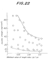
- Fig. 22 is a graph showing the relationship between the isostatic strength and the deformation amount, i.e., the maximum value of the length ratio L B /L A in the partition walls of one ceramic honeycomb structural body.
- the length ratio L B /L A was measured in advance, with respect to each partition wall which had been subjected to a large deformation and therefore predicted to become a destruction point.
- the isostatic destruction test was then performed with respect to a series of honeycomb structural bodies which are different in the partition wall thickness, so as to investigate the relationship between the isostatic strength and the length ratio L B /L A of the partition wall at the destruction point.
- Each honeycomb structural body subjected to such isostatic destruction test is of a standard size having a round shape with an outer diameter of approximately 100 mm.
- the curve on the upper side shows the data for a relatively thick partition wall and the curve on the lower side shows the data for a relatively thin partition wall. It has been revealed by such investigations that the isostatic strength tends to rapidly increase when the length ratio L B /L A decreases to 1.10 or less.
- Fig. 23 is a graph showing the dispersion, in a statistical sense, of the length ratio L B /L A assumed by those partition walls in arbitrary cross-section of one honeycomb structural body, which had been subjected to bending deformation.
- This graph schematically shows the frequency of various length ratio L B /L A assumed by such deformed partition walls. It is apparent that the frequency in question is dependent on the length ratio L B /L A of such partition walls.
- ceramic honeycomb structural bodies wherein all the partition walls have the length ratio L B /L A of 1.10 or less, and also ceramic honeycomb structural bodies which include partition walls having the length ratio L B /L A in excess of 1.10.
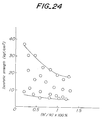
- Fig. 24 is a graph showing the relationship between the isostatic strength and the proportion (N'/N) ⁇ 100 % in quantity occupied by the number N' of the deformed partition walls each having a length ratio L B / A which is within a range between 1.10 and 1.15, with reference to the total number N of the partition walls.
- the curve on the upper side shows the data for a relatively thick partition wall
- the curve on the lower side shows the data for a relatively thin partition wall. It can be appreciated from this graph that the isostatic strength tends to rapidly increase when the above-mentioned quantity proportion decreases to 1.0 % or less.
- the reasons for such a tendency of the isostatic strength may be explained as follows. That is to say, an increased quantity proportion of the deformed partition walls often results in a higher probability of the occurrence of clusters wherein two or more deformed partition walls are located in succession as shown in Fig. 25A. In this instance, considerably deformed partition walls may be situated adjacent to each other.
- the honeycomb structural body with the above-mentioned clusters of the deformed partition walls is in clear contrast in terms of the local structural strength, with the honeycomb structural body wherein deformed partition walls are dispersed with an intervening distance from each other as shown in Fig. 25B. That is to say, when the deformed partition walls are clustered, the cell-like flow channels tend to be more readily crushed and the structural strength tends to decrease. Furthermore, in the case of an isostatic destruction test with respect to the honeycomb structural body wherein the deformed partition walls are clustered, the regions of the honeycomb structural body having a decreased strength become the destruction points to lower the isostatic strength as well.
- any flow passage in the honeycomb structural body may be deemed to have lattice points each defined by a center of the maximum inscribed circle inscribing at least three corners at an intersection of adjacent unit partition walls.
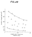
- the degree of the crush deformation of the partition walls can be conveniently quantified by a length ratio L max /L min of the maximum diagonal line length Lmax to the minimum diagonal line length L min .
- the above-mentioned length ratio L max /L min is within a range between 1 and 1.73 in the case of square cross-section of the flow passages shown in Fig. 26, and within a range between 1.15 and 1.93 in the case of hexagonal cross-section of the flow passages shown in Fig. 27A and Fig. 27B.
- Graphs shown in Fig. 28 and Fig. 29 illustrate the relationship of the length ratio L max /L min and the isostatic strength with reference to square cross-section and hexagonal cross-section of the flow passages, respectively, with the partition wall thickness as a parameter.
- the isostatic strength of the honeycomb structural body also tends to decrease when a gap is formed in any cross-section of the honeycomb structural body, due to a discontinuity of the partition wall in the flow passage direction.
- Fig. 30A and Fig. 30B the shapes of the partition walls with such a discontinuity as observed in the flow passage direction.
- the discontinuity of the partition wall may occur at a position between the lattice points or at the lattice points, and the number of lacks in both cases is counted to be 1.
- the number N DT of the partition walls having a discontinuity in the flow passage direction to form a gap in any cross-section of the honeycomb structural body is advantageously no more than 1.0 % of the total number N of the partition walls in the honeycomb structural body.
- the number N D20 of the partition walls included in that region and having a discontinuity in the flow passage direction to form a gap in any cross-section of the honeycomb structural body is advantageously no more than 0.5 % of the total number N of the partition walls in the honeycomb structural body.
- Fig. 31 and Fig. 32 are graphs showing the relationship between the isostatic strength and the number N D , N D20 of the partition walls having a discontinuity, respectively, with the partition wall thickness as the parameter.
- the curves on the upper sides show the data for relatively thick partition walls
- the curves on the lower sides show the data for relatively thin partition walls, respectively. It can be appreciated from Fig. 31 that the isostatic strength rapidly tends to rapidly increase when the proportion (N DT /N) ⁇ 100 % occupied by the number N D of the discontinuous partition walls with respect to the total number N of the partition walls in the honeycomb structural body as a whole is reduced to 1.0 % or less.
- the present invention a thin-walled ceramic honeycomb structural body with a reduced partition wall thickness as compared with that of the prior art structure, making it possible to realize an increased open frontal area and a reduced pressure loss, and to thereby decrease the heat capacity of the honeycomb structural body when it is used as the catalyst carrier.
- the present invention furthermore, it is also possible to provide a ceramic honeycomb structural body having practically satisfactory compressive strength characteristics notwithstanding the thin-walled structure, by satisfying the particular relationships between the partition wall thickness and the open frontal area and/or bulk density of the ceramic honeycomb structural body, and quantitatively maintaining the specifically defined ranges of the degree of deformation and the number of discontinuity or the like defects, which may occur in the partition walls in the production stage of the ceramic honeycomb structural body.
Landscapes
- Chemical & Material Sciences (AREA)
- Engineering & Computer Science (AREA)
- Chemical Kinetics & Catalysis (AREA)
- Materials Engineering (AREA)
- Organic Chemistry (AREA)
- Ceramic Engineering (AREA)
- Health & Medical Sciences (AREA)
- Toxicology (AREA)
- Combustion & Propulsion (AREA)
- Mechanical Engineering (AREA)
- General Engineering & Computer Science (AREA)
- Structural Engineering (AREA)
- Dispersion Chemistry (AREA)
- Catalysts (AREA)
- Exhaust Gas After Treatment (AREA)
Applications Claiming Priority (4)
| Application Number | Priority Date | Filing Date | Title |
|---|---|---|---|
| JP5188274A JP2892259B2 (ja) | 1993-07-29 | 1993-07-29 | セラミックハニカム触媒 |
| JP188273/93 | 1993-07-29 | ||
| JP188274/93 | 1993-07-29 | ||
| JP5188273A JP2892258B2 (ja) | 1993-07-29 | 1993-07-29 | セラミックハニカム構造体 |
Publications (2)
| Publication Number | Publication Date |
|---|---|
| EP0636410A1 true EP0636410A1 (fr) | 1995-02-01 |
| EP0636410B1 EP0636410B1 (fr) | 1997-08-20 |
Family
ID=26504828
Family Applications (1)
| Application Number | Title | Priority Date | Filing Date |
|---|---|---|---|
| EP94302077A Expired - Lifetime EP0636410B1 (fr) | 1993-07-29 | 1994-03-23 | Corps céramique structuré en nid d'abeille et catalyseur à base de celui-ci |
Country Status (6)
| Country | Link |
|---|---|
| US (1) | US5494881A (fr) |
| EP (1) | EP0636410B1 (fr) |
| KR (1) | KR100297621B1 (fr) |
| CN (1) | CN1092082C (fr) |
| CA (1) | CA2119604C (fr) |
| DE (1) | DE69405062T2 (fr) |
Cited By (6)
| Publication number | Priority date | Publication date | Assignee | Title |
|---|---|---|---|---|
| FR2778598A1 (fr) * | 1998-05-12 | 1999-11-19 | Ngk Insulators Ltd | Structure en nid d'abeilles a cellules hexagonales et procede de fixation de celle-ci |
| WO2005092504A1 (fr) * | 2004-03-12 | 2005-10-06 | Cormetech, Inc. | Systemes catalyseurs |
| US7658898B2 (en) | 2006-08-01 | 2010-02-09 | Cormetech, Inc. | Compositions and methods for treating exhaust gases |
| US7776786B2 (en) | 2004-05-04 | 2010-08-17 | Cormetech, Inc. | Catalyst systems advantageous for high particulate matter environments |
| DE102006035309B4 (de) * | 2005-12-27 | 2015-04-09 | Denso Corporation | Hexagonalzellenwabenstruktur |
| US10189017B2 (en) | 2013-01-25 | 2019-01-29 | Yara International Asa | Honeycomb monolith structure |
Families Citing this family (44)
| Publication number | Priority date | Publication date | Assignee | Title |
|---|---|---|---|---|
| US5866079A (en) * | 1993-09-03 | 1999-02-02 | Ngk Insulators, Ltd. | Ceramic honeycomb catalytic converter |
| CZ295523B6 (cs) * | 1997-03-21 | 2005-08-17 | Ecocat Oy | Katalytický reaktor |
| DE19749379A1 (de) * | 1997-11-07 | 1999-05-20 | Emitec Emissionstechnologie | Katalysator-Trägerkörper mit verbesserter Wärmeabstrahlung |
| US6540693B2 (en) * | 1998-03-03 | 2003-04-01 | Senorx, Inc. | Methods and apparatus for securing medical instruments to desired locations in a patients body |
| JP4453117B2 (ja) * | 1998-09-29 | 2010-04-21 | 株式会社デンソー | 六角ハニカム構造体の製造方法 |
| DE19921263A1 (de) * | 1999-05-07 | 2000-11-16 | Emitec Emissionstechnologie | Brennkraftmaschine mit einem kleinvolumigen Katalysator |
| JP3862458B2 (ja) * | 1999-11-15 | 2006-12-27 | 日本碍子株式会社 | ハニカム構造体 |
| US6623704B1 (en) * | 2000-02-22 | 2003-09-23 | Delphi Technologies, Inc. | Apparatus and method for manufacturing a catalytic converter |
| JP4548968B2 (ja) * | 2000-06-05 | 2010-09-22 | 株式会社日本自動車部品総合研究所 | セラミック担体およびセラミック触媒体 |
| US6821492B1 (en) * | 2000-09-13 | 2004-11-23 | Delphi Technologies, Inc. | Stronger catalyst using selective washcoat location |
| JP2003164761A (ja) * | 2001-09-21 | 2003-06-10 | Toshiba Corp | 金属酸化物焼結構造体及びその製造方法 |
| JP2003103181A (ja) * | 2001-09-28 | 2003-04-08 | Ngk Insulators Ltd | ハニカム触媒、ハニカム中間体及びハニカム触媒の製造方法 |
| JP4207422B2 (ja) * | 2001-12-04 | 2009-01-14 | 株式会社デンソー | ハニカム成形体の製造方法及び製造装置 |
| JP2003326175A (ja) * | 2002-03-07 | 2003-11-18 | Denso Corp | 担体とその製造方法、および触媒体 |
| JP3999001B2 (ja) * | 2002-03-08 | 2007-10-31 | 日本碍子株式会社 | ハニカム構造体及びそれを収納してなるキャニング構造体 |
| WO2003082467A1 (fr) * | 2002-03-28 | 2003-10-09 | Ngk Insulators, Ltd. | Corps structurel cellulaire, procede de fabrication d'un corps structurel cellulaire et corps structurel de catalyseur |
| JP3936238B2 (ja) * | 2002-05-20 | 2007-06-27 | 株式会社デンソー | 触媒体および触媒体の製造方法 |
| DE10225278A1 (de) * | 2002-06-04 | 2003-12-24 | Iav Gmbh | Abgaskatalysator und Katalysatorkörper, vorzugsweise für die Reinigung von Abgasen von Verbrennungsmotoren |
| EP1530672B1 (fr) * | 2002-07-15 | 2008-01-09 | Volkswagen Aktiengesellschaft | Installation de moteur a combustion interne comprenant un moteur a allumage par etincelle a injection directe et un systeme catalytique |
| JP4584555B2 (ja) * | 2002-10-17 | 2010-11-24 | 株式会社デンソー | セラミック触媒体 |
| US7435274B2 (en) * | 2003-02-27 | 2008-10-14 | Kabushiki Kaisha Toshiba | Metal particle-dispersed composite oxides, metal particle-dispersed composite oxide-sintered bodies, method of manufacturing metal particle-dispersed composite oxides, and hydrocarbon-based fuel reformer |
| JP4322542B2 (ja) * | 2003-04-21 | 2009-09-02 | 日本碍子株式会社 | ハニカム構造体、その製造方法及び成形用口金並びに排出流体浄化システム |
| JP5042827B2 (ja) * | 2005-06-29 | 2012-10-03 | イビデン株式会社 | ハニカム構造体 |
| JP4238858B2 (ja) * | 2005-09-20 | 2009-03-18 | 株式会社デンソー | 六角ハニカム構造体及びその製造方法 |
| JPWO2009141898A1 (ja) * | 2008-05-20 | 2011-09-29 | イビデン株式会社 | ハニカム構造体 |
| JP5506220B2 (ja) * | 2009-03-26 | 2014-05-28 | 日本碍子株式会社 | セラミックハニカム構造体 |
| EP2691173A1 (fr) * | 2011-03-28 | 2014-02-05 | Cormetech, Inc. | Compositions de catalyseur et leurs applications |
| WO2013016674A2 (fr) | 2011-07-27 | 2013-01-31 | Cormetech, Inc. | Appareil de combustion et ses applications |
| WO2013146955A1 (fr) * | 2012-03-30 | 2013-10-03 | 日本碍子株式会社 | Structure en nid d'abeilles |
| GB2502953B (en) | 2012-05-24 | 2017-02-08 | Imp Innovations Ltd | Catalytic converter substrate |
| CN103212451A (zh) * | 2013-04-19 | 2013-07-24 | 中电投远达环保工程有限公司 | 蜂窝催化剂单元及蜂窝催化剂模块 |
| CN105706284B (zh) * | 2013-11-08 | 2018-09-18 | 本田技研工业株式会社 | 双电源负载驱动燃料电池系统 |
| US10150082B2 (en) | 2014-05-28 | 2018-12-11 | Umicore Shokubai Japan Co., Ltd. | Catalyst for internal combustion engine exhaust gas purification, and system for same |
| WO2018044547A1 (fr) | 2016-08-31 | 2018-03-08 | Exxonmobil Chemical Patents Inc. | Pyrolyse d'hydrocarbures |
| US10711203B2 (en) | 2016-08-31 | 2020-07-14 | Exxonmobil Chemical Patents Inc. | Hydrocarbon pyrolysis |
| WO2018044555A1 (fr) | 2016-08-31 | 2018-03-08 | Exxonmobil Chemical Patents Inc. | Pyrolyse d'hydrocarbures |
| WO2018044557A1 (fr) | 2016-08-31 | 2018-03-08 | Exxonmobil Chemical Patents Inc. | Température d'approche de réacteur de pyrolyse |
| CN114700118B (zh) * | 2016-12-12 | 2024-05-07 | 康明泰克股份有限公司 | Scr催化剂模块及其对应的催化剂反应器 |
| JP6792489B2 (ja) | 2017-03-07 | 2020-11-25 | 日本碍子株式会社 | ハニカム構造体 |
| JP6622741B2 (ja) | 2017-03-07 | 2019-12-18 | 日本碍子株式会社 | ハニカム構造体 |
| US11279884B2 (en) | 2018-04-20 | 2022-03-22 | Exxonmobil Chemical Patents Inc. | Reverse flow reactors having low maldistribution parameter while containing asymmetric feeds, methods of using same, and pyrolysis products made from same |
| WO2019204082A1 (fr) | 2018-04-20 | 2019-10-24 | Exxonmobil Chemical Patents Inc. | Réacteurs à écoulement inversé ayant des rendements de purge élevés tout en contenant des alimentations asymétriques, leurs procédés d'utilisation et produits de pyrolyse fabriqués à partir de ceux-ci |
| JP7029421B2 (ja) * | 2019-02-28 | 2022-03-03 | 日本碍子株式会社 | ハニカム構造体用コーティング材、ハニカム構造体の外周コーティング及び外周コーティング付きハニカム構造体 |
| CN118976542B (zh) * | 2024-07-31 | 2025-11-28 | 山东国瓷功能材料股份有限公司 | 蜂窝陶瓷载体、其制备方法和含有该蜂窝陶瓷载体的催化体 |
Citations (2)
| Publication number | Priority date | Publication date | Assignee | Title |
|---|---|---|---|---|
| EP0241269A2 (fr) * | 1986-04-08 | 1987-10-14 | Ngk Insulators, Ltd. | Structure de céramique en nids d'abeilles de haute résistance |
| US4955524A (en) * | 1989-08-24 | 1990-09-11 | General Motors Corporation | Extrusion die construction and its method of manufacture |
Family Cites Families (2)
| Publication number | Priority date | Publication date | Assignee | Title |
|---|---|---|---|---|
| JPH084749B2 (ja) * | 1985-01-21 | 1996-01-24 | 日本碍子株式会社 | セラミツクハニカム構造体 |
| JPS61183182A (ja) * | 1985-02-11 | 1986-08-15 | 株式会社デンソー | 多孔質セラミツク構造体 |
-
1994
- 1994-03-22 CA CA002119604A patent/CA2119604C/fr not_active Expired - Lifetime
- 1994-03-23 US US08/216,429 patent/US5494881A/en not_active Expired - Lifetime
- 1994-03-23 DE DE69405062T patent/DE69405062T2/de not_active Expired - Lifetime
- 1994-03-23 EP EP94302077A patent/EP0636410B1/fr not_active Expired - Lifetime
- 1994-03-25 CN CN94103343A patent/CN1092082C/zh not_active Expired - Lifetime
- 1994-03-25 KR KR1019940006106A patent/KR100297621B1/ko not_active Expired - Lifetime
Patent Citations (2)
| Publication number | Priority date | Publication date | Assignee | Title |
|---|---|---|---|---|
| EP0241269A2 (fr) * | 1986-04-08 | 1987-10-14 | Ngk Insulators, Ltd. | Structure de céramique en nids d'abeilles de haute résistance |
| US4955524A (en) * | 1989-08-24 | 1990-09-11 | General Motors Corporation | Extrusion die construction and its method of manufacture |
Cited By (10)
| Publication number | Priority date | Publication date | Assignee | Title |
|---|---|---|---|---|
| FR2778598A1 (fr) * | 1998-05-12 | 1999-11-19 | Ngk Insulators Ltd | Structure en nid d'abeilles a cellules hexagonales et procede de fixation de celle-ci |
| US6421915B1 (en) | 1998-05-12 | 2002-07-23 | Ngk Insulators, Ltd. | Hexagonal-cell honeycomb structure and method for fixation thereof |
| WO2005092504A1 (fr) * | 2004-03-12 | 2005-10-06 | Cormetech, Inc. | Systemes catalyseurs |
| US7807110B2 (en) | 2004-03-12 | 2010-10-05 | Cormetech Inc. | Catalyst systems |
| EP2620215A1 (fr) * | 2004-03-12 | 2013-07-31 | Cormetech, Inc. | Systemes Catalyseurs |
| US7776786B2 (en) | 2004-05-04 | 2010-08-17 | Cormetech, Inc. | Catalyst systems advantageous for high particulate matter environments |
| DE102006035309B4 (de) * | 2005-12-27 | 2015-04-09 | Denso Corporation | Hexagonalzellenwabenstruktur |
| US7658898B2 (en) | 2006-08-01 | 2010-02-09 | Cormetech, Inc. | Compositions and methods for treating exhaust gases |
| US10189017B2 (en) | 2013-01-25 | 2019-01-29 | Yara International Asa | Honeycomb monolith structure |
| EP2948246B1 (fr) * | 2013-01-25 | 2020-06-17 | YARA International ASA | Utilisation d'une structure en nid d'abeille avec canaux de section allongée pour la réduction catalytique sélective d'oxydes d'azote |
Also Published As
| Publication number | Publication date |
|---|---|
| KR950002855A (ko) | 1995-02-16 |
| KR100297621B1 (ko) | 2001-10-22 |
| DE69405062T2 (de) | 1998-02-05 |
| CA2119604C (fr) | 1997-02-18 |
| EP0636410B1 (fr) | 1997-08-20 |
| DE69405062D1 (de) | 1997-09-25 |
| CN1098029A (zh) | 1995-02-01 |
| US5494881A (en) | 1996-02-27 |
| CA2119604A1 (fr) | 1995-01-30 |
| CN1092082C (zh) | 2002-10-09 |
Similar Documents
| Publication | Publication Date | Title |
|---|---|---|
| EP0636410B1 (fr) | Corps céramique structuré en nid d'abeille et catalyseur à base de celui-ci | |
| US7056365B2 (en) | Honeycomb structure, and honeycomb filter and converter system both using the same | |
| US6656564B2 (en) | Ceramic honeycomb structure | |
| EP0867222B1 (fr) | Structure céramique en nid d'abeilles avec différentes épaisseurs de parois | |
| EP0824184A2 (fr) | Pot catalytique céramique | |
| US7585478B2 (en) | Exhaust-gas purifying catalyst | |
| EP0283220B1 (fr) | Corps céramiques structuraux en forme de nid d'abeilles | |
| EP0724070A1 (fr) | Convertisseur catalytique en forme de nid d'abeille | |
| EP0997619A1 (fr) | Proportion des longueurs du plenum d'entree et de sortie d'un convertisseur catalytique | |
| US9976458B2 (en) | Honeycomb structure body | |
| KR20120095458A (ko) | 편향면을 구비한 배기가스 정화요소 및 그 제조방법 | |
| JP2892258B2 (ja) | セラミックハニカム構造体 | |
| DE3939921A1 (de) | Anordnung zur katalytischen reinigung der auspuffgase von verbrennungsmotoren, insbesondere nach dem zweitaktprinzip | |
| KR20080101889A (ko) | 개선된 스타트업 거동을 갖는 촉매 변환장치 | |
| JP2892259B2 (ja) | セラミックハニカム触媒 | |
| JP3093598B2 (ja) | 排ガス浄化装置 | |
| JP4788497B2 (ja) | 六角ハニカム構造体 | |
| Held et al. | Improved cell design for increased catalytic conversion efficiency | |
| Yamamoto et al. | Reduction of wall thickness of ceramic substrates for automotive catalysts | |
| Takada et al. | Development of a Highly Heat-Resistant Metal Supported Catalyst | |
| JP2011156537A (ja) | 六角ハニカム構造体 | |
| US11845032B2 (en) | Exhaust gas purification filter | |
| JP2001031465A (ja) | 高強度薄壁ハニカム構造体 | |
| EP0526611A1 (fr) | Catalyseur presentant une resistance mecanique elevee et econome en metaux nobles, et procede de fabrication. | |
| JPH04279717A (ja) | 内燃機関の排気ガス浄化装置 |
Legal Events
| Date | Code | Title | Description |
|---|---|---|---|
| PUAI | Public reference made under article 153(3) epc to a published international application that has entered the european phase |
Free format text: ORIGINAL CODE: 0009012 |
|
| AK | Designated contracting states |
Kind code of ref document: A1 Designated state(s): BE DE FR GB IT |
|
| 17P | Request for examination filed |
Effective date: 19950213 |
|
| GRAG | Despatch of communication of intention to grant |
Free format text: ORIGINAL CODE: EPIDOS AGRA |
|
| 17Q | First examination report despatched |
Effective date: 19961022 |
|
| GRAH | Despatch of communication of intention to grant a patent |
Free format text: ORIGINAL CODE: EPIDOS IGRA |
|
| GRAH | Despatch of communication of intention to grant a patent |
Free format text: ORIGINAL CODE: EPIDOS IGRA |
|
| GRAA | (expected) grant |
Free format text: ORIGINAL CODE: 0009210 |
|
| AK | Designated contracting states |
Kind code of ref document: B1 Designated state(s): BE DE FR GB IT |
|
| REF | Corresponds to: |
Ref document number: 69405062 Country of ref document: DE Date of ref document: 19970925 |
|
| ET | Fr: translation filed | ||
| ITF | It: translation for a ep patent filed | ||
| PLBE | No opposition filed within time limit |
Free format text: ORIGINAL CODE: 0009261 |
|
| STAA | Information on the status of an ep patent application or granted ep patent |
Free format text: STATUS: NO OPPOSITION FILED WITHIN TIME LIMIT |
|
| 26N | No opposition filed | ||
| REG | Reference to a national code |
Ref country code: GB Ref legal event code: IF02 |
|
| PGFP | Annual fee paid to national office [announced via postgrant information from national office to epo] |
Ref country code: IT Payment date: 20060331 Year of fee payment: 13 |
|
| PG25 | Lapsed in a contracting state [announced via postgrant information from national office to epo] |
Ref country code: IT Free format text: LAPSE BECAUSE OF NON-PAYMENT OF DUE FEES Effective date: 20070323 |
|
| PGFP | Annual fee paid to national office [announced via postgrant information from national office to epo] |
Ref country code: FR Payment date: 20130315 Year of fee payment: 20 Ref country code: GB Payment date: 20130225 Year of fee payment: 20 |
|
| PGFP | Annual fee paid to national office [announced via postgrant information from national office to epo] |
Ref country code: BE Payment date: 20130410 Year of fee payment: 20 Ref country code: DE Payment date: 20130328 Year of fee payment: 20 |
|
| REG | Reference to a national code |
Ref country code: DE Ref legal event code: R071 Ref document number: 69405062 Country of ref document: DE |
|
| REG | Reference to a national code |
Ref country code: DE Ref legal event code: R071 Ref document number: 69405062 Country of ref document: DE |
|
| BE20 | Be: patent expired |
Owner name: *NGK INSULATORS LTD Effective date: 20140323 |
|
| REG | Reference to a national code |
Ref country code: GB Ref legal event code: PE20 Expiry date: 20140322 |
|
| PG25 | Lapsed in a contracting state [announced via postgrant information from national office to epo] |
Ref country code: GB Free format text: LAPSE BECAUSE OF EXPIRATION OF PROTECTION Effective date: 20140322 Ref country code: DE Free format text: LAPSE BECAUSE OF EXPIRATION OF PROTECTION Effective date: 20140325 |