EP0636466A2 - Méthode pour la production de tubes ondulés en matière plastique - Google Patents
Méthode pour la production de tubes ondulés en matière plastique Download PDFInfo
- Publication number
- EP0636466A2 EP0636466A2 EP94111095A EP94111095A EP0636466A2 EP 0636466 A2 EP0636466 A2 EP 0636466A2 EP 94111095 A EP94111095 A EP 94111095A EP 94111095 A EP94111095 A EP 94111095A EP 0636466 A2 EP0636466 A2 EP 0636466A2
- Authority
- EP
- European Patent Office
- Prior art keywords
- spray head
- inner layer
- layer
- outer layer
- extruder
- Prior art date
- Legal status (The legal status is an assumption and is not a legal conclusion. Google has not performed a legal analysis and makes no representation as to the accuracy of the status listed.)
- Granted
Links
Images
Classifications
-
- B—PERFORMING OPERATIONS; TRANSPORTING
- B29—WORKING OF PLASTICS; WORKING OF SUBSTANCES IN A PLASTIC STATE IN GENERAL
- B29C—SHAPING OR JOINING OF PLASTICS; SHAPING OF MATERIAL IN A PLASTIC STATE, NOT OTHERWISE PROVIDED FOR; AFTER-TREATMENT OF THE SHAPED PRODUCTS, e.g. REPAIRING
- B29C48/00—Extrusion moulding, i.e. expressing the moulding material through a die or nozzle which imparts the desired form; Apparatus therefor
- B29C48/25—Component parts, details or accessories; Auxiliary operations
- B29C48/30—Extrusion nozzles or dies
- B29C48/303—Extrusion nozzles or dies using dies or die parts movable in a closed circuit, e.g. mounted on movable endless support
-
- B—PERFORMING OPERATIONS; TRANSPORTING
- B29—WORKING OF PLASTICS; WORKING OF SUBSTANCES IN A PLASTIC STATE IN GENERAL
- B29C—SHAPING OR JOINING OF PLASTICS; SHAPING OF MATERIAL IN A PLASTIC STATE, NOT OTHERWISE PROVIDED FOR; AFTER-TREATMENT OF THE SHAPED PRODUCTS, e.g. REPAIRING
- B29C48/00—Extrusion moulding, i.e. expressing the moulding material through a die or nozzle which imparts the desired form; Apparatus therefor
- B29C48/001—Combinations of extrusion moulding with other shaping operations
- B29C48/0013—Extrusion moulding in several steps, i.e. components merging outside the die
- B29C48/0015—Extrusion moulding in several steps, i.e. components merging outside the die producing hollow articles having components brought in contact outside the extrusion die
-
- B—PERFORMING OPERATIONS; TRANSPORTING
- B29—WORKING OF PLASTICS; WORKING OF SUBSTANCES IN A PLASTIC STATE IN GENERAL
- B29C—SHAPING OR JOINING OF PLASTICS; SHAPING OF MATERIAL IN A PLASTIC STATE, NOT OTHERWISE PROVIDED FOR; AFTER-TREATMENT OF THE SHAPED PRODUCTS, e.g. REPAIRING
- B29C48/00—Extrusion moulding, i.e. expressing the moulding material through a die or nozzle which imparts the desired form; Apparatus therefor
- B29C48/03—Extrusion moulding, i.e. expressing the moulding material through a die or nozzle which imparts the desired form; Apparatus therefor characterised by the shape of the extruded material at extrusion
- B29C48/09—Articles with cross-sections having partially or fully enclosed cavities, e.g. pipes or channels
-
- B—PERFORMING OPERATIONS; TRANSPORTING
- B29—WORKING OF PLASTICS; WORKING OF SUBSTANCES IN A PLASTIC STATE IN GENERAL
- B29C—SHAPING OR JOINING OF PLASTICS; SHAPING OF MATERIAL IN A PLASTIC STATE, NOT OTHERWISE PROVIDED FOR; AFTER-TREATMENT OF THE SHAPED PRODUCTS, e.g. REPAIRING
- B29C48/00—Extrusion moulding, i.e. expressing the moulding material through a die or nozzle which imparts the desired form; Apparatus therefor
- B29C48/03—Extrusion moulding, i.e. expressing the moulding material through a die or nozzle which imparts the desired form; Apparatus therefor characterised by the shape of the extruded material at extrusion
- B29C48/13—Articles with a cross-section varying in the longitudinal direction, e.g. corrugated pipes
-
- B—PERFORMING OPERATIONS; TRANSPORTING
- B29—WORKING OF PLASTICS; WORKING OF SUBSTANCES IN A PLASTIC STATE IN GENERAL
- B29C—SHAPING OR JOINING OF PLASTICS; SHAPING OF MATERIAL IN A PLASTIC STATE, NOT OTHERWISE PROVIDED FOR; AFTER-TREATMENT OF THE SHAPED PRODUCTS, e.g. REPAIRING
- B29C48/00—Extrusion moulding, i.e. expressing the moulding material through a die or nozzle which imparts the desired form; Apparatus therefor
- B29C48/16—Articles comprising two or more components, e.g. co-extruded layers
- B29C48/18—Articles comprising two or more components, e.g. co-extruded layers the components being layers
- B29C48/21—Articles comprising two or more components, e.g. co-extruded layers the components being layers the layers being joined at their surfaces
-
- B—PERFORMING OPERATIONS; TRANSPORTING
- B29—WORKING OF PLASTICS; WORKING OF SUBSTANCES IN A PLASTIC STATE IN GENERAL
- B29C—SHAPING OR JOINING OF PLASTICS; SHAPING OF MATERIAL IN A PLASTIC STATE, NOT OTHERWISE PROVIDED FOR; AFTER-TREATMENT OF THE SHAPED PRODUCTS, e.g. REPAIRING
- B29C48/00—Extrusion moulding, i.e. expressing the moulding material through a die or nozzle which imparts the desired form; Apparatus therefor
- B29C48/25—Component parts, details or accessories; Auxiliary operations
- B29C48/285—Feeding the extrusion material to the extruder
-
- B—PERFORMING OPERATIONS; TRANSPORTING
- B29—WORKING OF PLASTICS; WORKING OF SUBSTANCES IN A PLASTIC STATE IN GENERAL
- B29C—SHAPING OR JOINING OF PLASTICS; SHAPING OF MATERIAL IN A PLASTIC STATE, NOT OTHERWISE PROVIDED FOR; AFTER-TREATMENT OF THE SHAPED PRODUCTS, e.g. REPAIRING
- B29C48/00—Extrusion moulding, i.e. expressing the moulding material through a die or nozzle which imparts the desired form; Apparatus therefor
- B29C48/001—Combinations of extrusion moulding with other shaping operations
- B29C48/0012—Combinations of extrusion moulding with other shaping operations combined with shaping by internal pressure generated in the material, e.g. foaming
-
- B—PERFORMING OPERATIONS; TRANSPORTING
- B29—WORKING OF PLASTICS; WORKING OF SUBSTANCES IN A PLASTIC STATE IN GENERAL
- B29C—SHAPING OR JOINING OF PLASTICS; SHAPING OF MATERIAL IN A PLASTIC STATE, NOT OTHERWISE PROVIDED FOR; AFTER-TREATMENT OF THE SHAPED PRODUCTS, e.g. REPAIRING
- B29C48/00—Extrusion moulding, i.e. expressing the moulding material through a die or nozzle which imparts the desired form; Apparatus therefor
- B29C48/25—Component parts, details or accessories; Auxiliary operations
- B29C48/285—Feeding the extrusion material to the extruder
- B29C48/286—Raw material dosing
-
- B—PERFORMING OPERATIONS; TRANSPORTING
- B29—WORKING OF PLASTICS; WORKING OF SUBSTANCES IN A PLASTIC STATE IN GENERAL
- B29C—SHAPING OR JOINING OF PLASTICS; SHAPING OF MATERIAL IN A PLASTIC STATE, NOT OTHERWISE PROVIDED FOR; AFTER-TREATMENT OF THE SHAPED PRODUCTS, e.g. REPAIRING
- B29C48/00—Extrusion moulding, i.e. expressing the moulding material through a die or nozzle which imparts the desired form; Apparatus therefor
- B29C48/25—Component parts, details or accessories; Auxiliary operations
- B29C48/285—Feeding the extrusion material to the extruder
- B29C48/288—Feeding the extrusion material to the extruder in solid form, e.g. powder or granules
- B29C48/2883—Feeding the extrusion material to the extruder in solid form, e.g. powder or granules of preformed parts, e.g. inserts, retaining their shape during the extrusion process
-
- B—PERFORMING OPERATIONS; TRANSPORTING
- B29—WORKING OF PLASTICS; WORKING OF SUBSTANCES IN A PLASTIC STATE IN GENERAL
- B29K—INDEXING SCHEME ASSOCIATED WITH SUBCLASSES B29B, B29C OR B29D, RELATING TO MOULDING MATERIALS OR TO MATERIALS FOR MOULDS, REINFORCEMENTS, FILLERS OR PREFORMED PARTS, e.g. INSERTS
- B29K2105/00—Condition, form or state of moulded material or of the material to be shaped
- B29K2105/04—Condition, form or state of moulded material or of the material to be shaped cellular or porous
-
- B—PERFORMING OPERATIONS; TRANSPORTING
- B29—WORKING OF PLASTICS; WORKING OF SUBSTANCES IN A PLASTIC STATE IN GENERAL
- B29L—INDEXING SCHEME ASSOCIATED WITH SUBCLASS B29C, RELATING TO PARTICULAR ARTICLES
- B29L2016/00—Articles with corrugations or pleats
-
- B—PERFORMING OPERATIONS; TRANSPORTING
- B29—WORKING OF PLASTICS; WORKING OF SUBSTANCES IN A PLASTIC STATE IN GENERAL
- B29L—INDEXING SCHEME ASSOCIATED WITH SUBCLASS B29C, RELATING TO PARTICULAR ARTICLES
- B29L2023/00—Tubular articles
- B29L2023/18—Pleated or corrugated hoses
Definitions
- the invention relates to a method for producing finned tubes made of plastic, which have an inner layer with a smooth inner tube surface and an outer layer with a curved outer tube surface, the material for the inner layer and the material for the outer layer being extruded separately from one another into a mold cavity by a spray head , which is defined by a cooling mandrel connected to the spray head and the mold jaws of a corrugator, one layer of the tube being formed by a foam expanding by means of a chemical blowing agent, and a device for producing an inner layer with a smooth inner tube surface and an outer layer with a Domed finned tubes having a first extruder for the material of the outer layer, a second extruder for the material of the inner layer, a spray head connected to the first and second extruder, the two n materials has two concentric annular nozzle channels, a cooling mandrel coaxially adjacent to the spray head and a corrugator enclosing the spray head and cooling mandrel, the mold
- Such a method and an apparatus for carrying out the method are known from DE 41 28 654 A1.
- Said conduit has a smooth inner tube surface and is formed with an associated corrugated and compact outer tube.
- An intermediate tube is provided between the inner tube surface and the outer tube, which has a different nature than the outer tube.
- the intermediate tube preferably consists of a foam material. In any case, there is a corrugated outer tube there, which requires an appropriately designed spray head.
- outer tube To implement the outer tube, it is necessary to run the corresponding outer compact mass flow for the outer tube after exiting the spray head against the shaped jaws of the corrugator by means of compressed air or to suck it onto the shaped jaws of the corrugator by means of a vacuum, after which demolding and cooling take place. This requires a not insignificant effort.
- there is an at least three-layer composite pipe consisting of the corrugated outer pipe, the smooth inner pipe and the intermediate layer located therebetween of foam expanded by means of a chemical blowing agent, the intermediate layer either being provided parallel to the smooth cylindrical inner pipe or completely filling the intermediate space.
- Outer tube, intermediate tube and inner tube can be made of PVC, PE and / or PP.
- All pipe layers can be made from the same material there, the intermediate pipe being a foam or a compact one Has structure and can consist of an original plastic or a recycled plastic.
- the invention has for its object to provide a method and an apparatus of the type mentioned, it being possible in a simple manner to manufacture finned tubes from only two layers comparatively easily and inexpensively.
- This object is achieved according to the process in that a non-sorted, washed and crushed recyclate is used as material for the outer layer having a ribbed longitudinal profile, which is mixed with a suitable blowing agent through a first extruder provided with a tamping device or other positive feed into the spray head is introduced, from which it is separated from the new material for the tubular inner layer and emerges concentrically surrounding it, and the material for the outer layer foams after exiting the spray head in the space between the inner layer and the mold jaws of the corrugator.
- a non-sorted and only mechanically crushed recyclate is used for the outer layer of the finned tube. Regranulation can therefore be omitted according to the invention.
- the recyclate can be a mixture of different polyolefins such as LDPE, MDPE, HDPE, PP or the like. act. Another advantage is that landfill costs are avoided as a result of the reuse of the recyclate according to the invention, which is important from an environmental point of view.
- the blowing agent mixed with the washed and crushed recyclate can be, for example, Hydrocerol CF 40E (Trademark of Boehringer Ingelheim KG.), which is available in the form of white cylindrical granules.
- any mixture of common polyolefins other than PVC is preferably used for the outer layer.
- a pure plastic material is preferably used for the inner layer. This is, for example, polyethylene.
- the object on which the invention is based is achieved according to the device in that the first extruder for mixing washed and comminuted, non-sorted recyclate is provided with a suitable blowing agent with a tamping device or another positive feed, and in that the two ring nozzle channels with their nozzle openings from that Open the face of the spray head facing the cooling mandrel at the same axial height.
- the washed and comminuted, non-sorted recyclate is mixed with the suitable blowing agent, the tamping device or in particular in the first extruder giving such a pressure that the blowing agent is only effective, after the Extrusion pressure in the first extruder or in the spray head downstream after the nozzle opening is no longer present, so that the material for the outer layer can only foam here.
- the two ring nozzle channels with their nozzle openings In order to prevent the foaming material for the outer layer from sticking to the corresponding nozzle opening, which would lead to coking of said material, it has proven expedient for the two ring nozzle channels with their nozzle openings to be axially directed out of the end face of the spray head facing the cooling mandrel flow out at the same height. This is the only way to ensure smooth production of the finned tubes according to the invention.
- the tamping device or the forced feed can have a funnel-shaped housing in which a stuffing screw device is mounted, which has a first conical screw and a second cylindrical screw extending centrally through it.
- the device according to the invention can be of relatively simple design because it is sufficient if the spray head is provided with a single air supply opening into the space between the cooling mandrel and the inner layer. According to the invention, it is advantageously possible to dispense with a further air supply for compressed air forming an outer layer or for vacuuming the mold jaws of the corrugator, as is required in the prior art according to DE 41 28 654 A1 mentioned at the beginning.
- a very considerable advantage of the method according to the invention or the device according to the invention for carrying out this method is that the recyclate used is in a particularly inexpensive form because a Separation of the type of recyclate according to the invention is not necessary. If one considers the effort with which such a separation of the various plastic materials has so far been carried out, it can be estimated which advantages the method and the device according to the invention have.
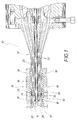
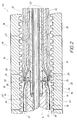
- FIG. 1 shows sections of a device 10 for producing finned tubes, the device 10 having a spray head 12, a cooling mandrel 14 in the vicinity of the spray head 12 and axially adjacent thereto, and a corrugator 16 with mold jaws 18.
- the spray head 12 is with a first ring nozzle channel 20 and formed with a second ring nozzle channel 22, which are provided concentrically with each other and open with their nozzle openings 24 and 26 from the end face 28 of the spray head 12 facing the cooling mandrel 14.
- the annular and concentric nozzle openings 24 and 26 thus open out at the same axial height from the spray head 12.
- the first ring nozzle channel 20 is connected to a first extruder (not shown) and the second ring nozzle channel is connected to a second extruder (not shown).
- the spray head 12 is formed with an air supply 30 which leads into the space between the cooling mandrel 14 and that from the nozzle opening 26 of the second ring nozzle channel 22 emerges from the inner layer 32.
- the inner layer 32 consists of a pure plastic material, preferably of polyethylene. After emerging from the nozzle opening 26, the inner layer 32 slides over the smooth outer surface 34 of the cooling mandrel 14.
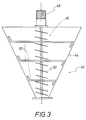
- FIG. 3 shows a tamping device 42 with a conically tapering, funnel-shaped housing 44, in which a stuffing screw device 46 is rotatably mounted.
- the stuffing screw device 46 is connected to a drive motor 48, it has a first conical screw 50 and a second cylindrical screw 52 which extends centrally through the conical first screw 50.
- the tamping device 42 serves to mix the non-sorted, washed and shredded recyclate with a suitable blowing agent and is connected to the first extruder (not shown) belonging to the first ring nozzle channel 20 (see FIGS. 1 and 2).
Landscapes
- Engineering & Computer Science (AREA)
- Mechanical Engineering (AREA)
- Manufacturing & Machinery (AREA)
- Extrusion Moulding Of Plastics Or The Like (AREA)
- Shaping Of Tube Ends By Bending Or Straightening (AREA)
Applications Claiming Priority (2)
| Application Number | Priority Date | Filing Date | Title |
|---|---|---|---|
| DE4325021A DE4325021C1 (de) | 1993-07-26 | 1993-07-26 | Verfahren und Vorrichtung zur Herstellung von Rippenrohren aus Kunststoff |
| DE4325021 | 1993-07-26 |
Publications (3)
| Publication Number | Publication Date |
|---|---|
| EP0636466A2 true EP0636466A2 (fr) | 1995-02-01 |
| EP0636466A3 EP0636466A3 (fr) | 1995-03-29 |
| EP0636466B1 EP0636466B1 (fr) | 1997-01-22 |
Family
ID=6493717
Family Applications (1)
| Application Number | Title | Priority Date | Filing Date |
|---|---|---|---|
| EP94111095A Expired - Lifetime EP0636466B1 (fr) | 1993-07-26 | 1994-07-16 | Méthode pour la production de tubes ondulés en matière plastique |
Country Status (3)
| Country | Link |
|---|---|
| EP (1) | EP0636466B1 (fr) |
| DE (2) | DE4325021C1 (fr) |
| ES (1) | ES2098830T3 (fr) |
Cited By (2)
| Publication number | Priority date | Publication date | Assignee | Title |
|---|---|---|---|---|
| WO2001089785A1 (fr) * | 2000-05-22 | 2001-11-29 | Uponor Limited | Tuyau recycle |
| CN113459454A (zh) * | 2021-06-09 | 2021-10-01 | 安徽森泰木塑科技地板有限公司 | 增强发泡地板、其制备用的挤出模具和设备组 |
Families Citing this family (5)
| Publication number | Priority date | Publication date | Assignee | Title |
|---|---|---|---|---|
| DE19604311A1 (de) * | 1996-02-07 | 1997-08-14 | Ralph Peter Dr Ing Hegler | Verbundrohr mit Muffe und Verfahren zu seiner Herstellung |
| DE29616289U1 (de) * | 1996-09-19 | 1996-11-28 | Unicor Rohrsysteme GmbH, 97437 Haßfurt | Mehrschichtiges Kunststoffrohr |
| DE19640928A1 (de) * | 1996-10-04 | 1998-04-09 | Ralph Peter Dr Ing Hegler | Vorrichtung zur Herstellung von Kunststoff-Verbund-Rohren |
| DE19827435C2 (de) * | 1998-06-19 | 2000-06-08 | Kirchner Fraenk Rohr | Rohrförmiger Hohlkörper mit Wellungen mit einer Verschlußeinrichtung sowie Verfahren zur Herstellung eines deratigen rohrförmigen Hohlkörpers |
| DE10117126C1 (de) * | 2001-04-06 | 2002-08-01 | Unicor Rohrsysteme Gmbh | Vorrichtung zur Herstellung von Doppelwand-Wellrohren |
Family Cites Families (10)
| Publication number | Priority date | Publication date | Assignee | Title |
|---|---|---|---|---|
| US3496601A (en) * | 1967-04-14 | 1970-02-24 | Midland Ross Corp | Feeder for auger-type extruder |
| NL6816207A (fr) * | 1967-11-16 | 1969-05-20 | ||
| DE2042031A1 (de) * | 1970-08-25 | 1972-05-31 | Reifenhaeuser Kg | Verfahren und Vorrichtung zur Herstellung von Wellrohren aus thermoplastischem Kunststoff |
| AT352386B (de) * | 1972-10-19 | 1979-09-10 | Kagerer Eisen Kunststoff | Verfahren und vorrichtung zum kontinuierlichen herstellen von aus mindestens zwei schichten bestehenden kunststoffrohren mit querprofilierungen |
| DE3513708C2 (de) * | 1985-04-12 | 1994-04-21 | Drossbach Gmbh & Co Kg | Extrusionskopf zur Herstellung doppelwandiger Kunststoffrohre mit zylindrischem Innenrohr und quergewelltem Außenrohr |
| DE8509929U1 (de) * | 1985-04-03 | 1986-07-31 | Hewing GmbH & Co, 4434 Ochtrup | Isoliertes Kunststoffrohr |
| US4958770A (en) * | 1989-05-03 | 1990-09-25 | Prescision Porous Pipe, Inc. | Process for making uniform porosity flexible irrigation pipe |
| DE4128654C2 (de) * | 1991-08-29 | 1995-05-18 | Wolfgang Mayer | Mehrschichtiges Leitungsrohr aus Kunststoff und Verfahren zu dessen Herstellung |
| CA2056060A1 (fr) * | 1991-11-22 | 1993-05-23 | Manfred A. A. Lupke | Methode permettant de modifier un tuyau ondule ou cannele afin d'obtenir une paroi exterieure lisse |
| DE4204759C1 (fr) * | 1992-02-18 | 1992-12-03 | Friedrich Theysohn Gmbh, 3012 Langenhagen, De |
-
1993
- 1993-07-26 DE DE4325021A patent/DE4325021C1/de not_active Expired - Fee Related
-
1994
- 1994-07-16 ES ES94111095T patent/ES2098830T3/es not_active Expired - Lifetime
- 1994-07-16 DE DE59401640T patent/DE59401640D1/de not_active Expired - Fee Related
- 1994-07-16 EP EP94111095A patent/EP0636466B1/fr not_active Expired - Lifetime
Cited By (3)
| Publication number | Priority date | Publication date | Assignee | Title |
|---|---|---|---|---|
| WO2001089785A1 (fr) * | 2000-05-22 | 2001-11-29 | Uponor Limited | Tuyau recycle |
| CN113459454A (zh) * | 2021-06-09 | 2021-10-01 | 安徽森泰木塑科技地板有限公司 | 增强发泡地板、其制备用的挤出模具和设备组 |
| CN113459454B (zh) * | 2021-06-09 | 2022-03-11 | 安徽森泰木塑科技地板有限公司 | 增强发泡地板、其制备用的挤出模具和设备组 |
Also Published As
| Publication number | Publication date |
|---|---|
| EP0636466A3 (fr) | 1995-03-29 |
| ES2098830T3 (es) | 1997-05-01 |
| DE4325021C1 (de) | 1995-03-02 |
| EP0636466B1 (fr) | 1997-01-22 |
| DE59401640D1 (de) | 1997-03-06 |
Similar Documents
| Publication | Publication Date | Title |
|---|---|---|
| EP0995579B1 (fr) | Procédé de production en continu d'un tube composite avec manchon, et appareil pour la mise en oeuvre du procédé | |
| DE1629364B2 (de) | Verfahren und vorrichtung zum extrudieren einer aus thermoplastischen kunststoffen bestehenden verbundbahn | |
| DE2456986B2 (de) | Vorrichtung zum kalibrieren und kuehlen von stranggepressten kunststoffrohren | |
| DE2557511A1 (de) | Vorrichtung zum extrudieren von plastomerem oder elastomerem material um wenigstens zwei faeden, draehte o.dgl. herum | |
| DE69629491T2 (de) | Verfahren zum herstellen von homogenen materialien mit einem extruder, und extruder | |
| DE69707763T2 (de) | Verfahren und Vorrichtung zum Herstellen von Rohren aus wiederverwendetem thermoplastischem Kunststoff | |
| DE4325021C1 (de) | Verfahren und Vorrichtung zur Herstellung von Rippenrohren aus Kunststoff | |
| DE4411164C1 (de) | Verfahren und Vorrichtung zum Herstellen eines aufschäumbaren Kunststoffs | |
| DE3044535A1 (de) | Verfahren und vorrichtung zur herstellung mehrschichtiger kunststoffprofile, insbesondere kunststoffrohre | |
| EP3872382B1 (fr) | Conduite thermo-isolée | |
| DE3513708A1 (de) | Verfahren und einrichtung zur herstellung von doppelwandigen rohren | |
| CH674762A5 (fr) | ||
| DE10046454B4 (de) | Verfahren zum Durchspülen polymer beziehungsweise kunststoffschmelzeführender Teile von Folienextrusionanlagen | |
| DE102018108308A1 (de) | Mehrschichtige blasgeformte Extrusion | |
| DE4135336C2 (de) | Verfahren zum Strangpressen von Mehrschichtrohren | |
| EP0879142B1 (fr) | Tuyau en plastique multicouche | |
| EP2225083B1 (fr) | Procédé de fabrication de une pré-ébauche et l'utilisation du procédé | |
| DE3109216C2 (de) | Verfahren und Vorrichtung zum Ummanteln eines Stahlrohres | |
| DE19956880B4 (de) | Kunststoffrohr mit umgebenden Rippenrohr | |
| DE10205210B4 (de) | Vorrichtung zur Herstellung von Kunststoffrohren | |
| DE10237051A1 (de) | Verfahren und Vorrichtung zur Herstellung blasgeformter Hohlkörper aus thermoplastischen Kunststoffen | |
| EP0114212A2 (fr) | Procédé et dispositif pour fabriquer des tuyaux flexibles en matière plastique | |
| DE19504865A1 (de) | Füllvorrichtung für Treibstoff und Verfahren zu deren Herstellung | |
| EP1985433B1 (fr) | Procédé de fabrication de profilés en plastique tubulaires | |
| DE19851076A1 (de) | Verfahren und Vorrichtung zur Herstellung eines Zusatzteils für ein technisches Formteil |
Legal Events
| Date | Code | Title | Description |
|---|---|---|---|
| PUAI | Public reference made under article 153(3) epc to a published international application that has entered the european phase |
Free format text: ORIGINAL CODE: 0009012 |
|
| AK | Designated contracting states |
Kind code of ref document: A2 Designated state(s): DE ES FR GB IT SE |
|
| PUAL | Search report despatched |
Free format text: ORIGINAL CODE: 0009013 |
|
| AK | Designated contracting states |
Kind code of ref document: A3 Designated state(s): DE ES FR GB IT SE |
|
| 17P | Request for examination filed |
Effective date: 19950310 |
|
| 17Q | First examination report despatched |
Effective date: 19951207 |
|
| GRAG | Despatch of communication of intention to grant |
Free format text: ORIGINAL CODE: EPIDOS AGRA |
|
| GRAH | Despatch of communication of intention to grant a patent |
Free format text: ORIGINAL CODE: EPIDOS IGRA |
|
| GRAH | Despatch of communication of intention to grant a patent |
Free format text: ORIGINAL CODE: EPIDOS IGRA |
|
| GRAA | (expected) grant |
Free format text: ORIGINAL CODE: 0009210 |
|
| AK | Designated contracting states |
Kind code of ref document: B1 Designated state(s): DE ES FR GB IT SE |
|
| GBT | Gb: translation of ep patent filed (gb section 77(6)(a)/1977) |
Effective date: 19970206 |
|
| REF | Corresponds to: |
Ref document number: 59401640 Country of ref document: DE Date of ref document: 19970306 |
|
| ET | Fr: translation filed | ||
| ITF | It: translation for a ep patent filed | ||
| REG | Reference to a national code |
Ref country code: ES Ref legal event code: FG2A Ref document number: 2098830 Country of ref document: ES Kind code of ref document: T3 |
|
| PLBE | No opposition filed within time limit |
Free format text: ORIGINAL CODE: 0009261 |
|
| STAA | Information on the status of an ep patent application or granted ep patent |
Free format text: STATUS: NO OPPOSITION FILED WITHIN TIME LIMIT |
|
| 26N | No opposition filed | ||
| REG | Reference to a national code |
Ref country code: GB Ref legal event code: IF02 |
|
| PGFP | Annual fee paid to national office [announced via postgrant information from national office to epo] |
Ref country code: GB Payment date: 20020625 Year of fee payment: 9 |
|
| PGFP | Annual fee paid to national office [announced via postgrant information from national office to epo] |
Ref country code: DE Payment date: 20020715 Year of fee payment: 9 |
|
| PGFP | Annual fee paid to national office [announced via postgrant information from national office to epo] |
Ref country code: FR Payment date: 20020717 Year of fee payment: 9 |
|
| PGFP | Annual fee paid to national office [announced via postgrant information from national office to epo] |
Ref country code: SE Payment date: 20020723 Year of fee payment: 9 |
|
| PGFP | Annual fee paid to national office [announced via postgrant information from national office to epo] |
Ref country code: ES Payment date: 20020724 Year of fee payment: 9 |
|
| PG25 | Lapsed in a contracting state [announced via postgrant information from national office to epo] |
Ref country code: GB Free format text: LAPSE BECAUSE OF NON-PAYMENT OF DUE FEES Effective date: 20030716 |
|
| PG25 | Lapsed in a contracting state [announced via postgrant information from national office to epo] |
Ref country code: SE Free format text: LAPSE BECAUSE OF NON-PAYMENT OF DUE FEES Effective date: 20030717 Ref country code: ES Free format text: LAPSE BECAUSE OF NON-PAYMENT OF DUE FEES Effective date: 20030717 |
|
| PG25 | Lapsed in a contracting state [announced via postgrant information from national office to epo] |
Ref country code: DE Free format text: LAPSE BECAUSE OF NON-PAYMENT OF DUE FEES Effective date: 20040203 |
|
| EUG | Se: european patent has lapsed | ||
| GBPC | Gb: european patent ceased through non-payment of renewal fee |
Effective date: 20030716 |
|
| PG25 | Lapsed in a contracting state [announced via postgrant information from national office to epo] |
Ref country code: FR Free format text: LAPSE BECAUSE OF NON-PAYMENT OF DUE FEES Effective date: 20040331 |
|
| REG | Reference to a national code |
Ref country code: FR Ref legal event code: ST |
|
| REG | Reference to a national code |
Ref country code: ES Ref legal event code: FD2A Effective date: 20030717 |
|
| PG25 | Lapsed in a contracting state [announced via postgrant information from national office to epo] |
Ref country code: IT Free format text: LAPSE BECAUSE OF NON-PAYMENT OF DUE FEES Effective date: 20050716 |