EP0636552A2 - Schraubkappe mit abtrennbarem Sicherheitsabschnitt und Dichtungsring - Google Patents
Schraubkappe mit abtrennbarem Sicherheitsabschnitt und Dichtungsring Download PDFInfo
- Publication number
- EP0636552A2 EP0636552A2 EP94830252A EP94830252A EP0636552A2 EP 0636552 A2 EP0636552 A2 EP 0636552A2 EP 94830252 A EP94830252 A EP 94830252A EP 94830252 A EP94830252 A EP 94830252A EP 0636552 A2 EP0636552 A2 EP 0636552A2
- Authority
- EP
- European Patent Office
- Prior art keywords
- cap
- dispenser
- safety strip
- lateral surface
- container
- Prior art date
- Legal status (The legal status is an assumption and is not a legal conclusion. Google has not performed a legal analysis and makes no representation as to the accuracy of the status listed.)
- Withdrawn
Links
Images

Classifications
-
- B—PERFORMING OPERATIONS; TRANSPORTING
- B65—CONVEYING; PACKING; STORING; HANDLING THIN OR FILAMENTARY MATERIAL
- B65D—CONTAINERS FOR STORAGE OR TRANSPORT OF ARTICLES OR MATERIALS, e.g. BAGS, BARRELS, BOTTLES, BOXES, CANS, CARTONS, CRATES, DRUMS, JARS, TANKS, HOPPERS, FORWARDING CONTAINERS; ACCESSORIES, CLOSURES, OR FITTINGS THEREFOR; PACKAGING ELEMENTS; PACKAGES
- B65D41/00—Caps, e.g. crown caps or crown seals, i.e. members having parts arranged for engagement with the external periphery of a neck or wall defining a pouring opening or discharge aperture; Protective cap-like covers for closure members, e.g. decorative covers of metal foil or paper
- B65D41/02—Caps or cap-like covers without lines of weakness, tearing strips, tags, or like opening or removal devices
- B65D41/04—Threaded or like caps or cap-like covers secured by rotation
- B65D41/0407—Threaded or like caps or cap-like covers secured by rotation with integral sealing means
- B65D41/0428—Threaded or like caps or cap-like covers secured by rotation with integral sealing means formed by a collar, flange, rib or the like contacting the top rim or the top edges or the external surface of a container neck
-
- B—PERFORMING OPERATIONS; TRANSPORTING
- B65—CONVEYING; PACKING; STORING; HANDLING THIN OR FILAMENTARY MATERIAL
- B65D—CONTAINERS FOR STORAGE OR TRANSPORT OF ARTICLES OR MATERIALS, e.g. BAGS, BARRELS, BOTTLES, BOXES, CANS, CARTONS, CRATES, DRUMS, JARS, TANKS, HOPPERS, FORWARDING CONTAINERS; ACCESSORIES, CLOSURES, OR FITTINGS THEREFOR; PACKAGING ELEMENTS; PACKAGES
- B65D41/00—Caps, e.g. crown caps or crown seals, i.e. members having parts arranged for engagement with the external periphery of a neck or wall defining a pouring opening or discharge aperture; Protective cap-like covers for closure members, e.g. decorative covers of metal foil or paper
- B65D41/32—Caps or cap-like covers with lines of weakness, tearing-strips, tags, or like opening or removal devices, e.g. to facilitate formation of pouring openings
- B65D41/34—Threaded or like caps or cap-like covers provided with tamper elements formed in, or attached to, the closure skirt
- B65D41/3423—Threaded or like caps or cap-like covers provided with tamper elements formed in, or attached to, the closure skirt with flexible tabs, or elements rotated from a non-engaging to an engaging position, formed on the tamper element or in the closure skirt
- B65D41/3438—Threaded or like caps or cap-like covers provided with tamper elements formed in, or attached to, the closure skirt with flexible tabs, or elements rotated from a non-engaging to an engaging position, formed on the tamper element or in the closure skirt the tamper element being formed separately but connected to the closure
Definitions
- the invention relates to a hermetic closure in a cap assembly for containers equipped with dispensers devices.
- a hermetic closure for containers having a small opening provided on a dispenser, such as a spout, a spray, a drop-counter and the like, where factory sealing of the container is guaranteed by a safety device that is broken on first use of the container.
- This safety device is usually a detachable safety strip connected to a a cap by easy-break struts, which are fractured by an axial movement of the cap in an upwards direction, that is to say in an opening direction of the container. This usually means an unscrewing movement.
- the cap is generally made in fairly rigid plastic material, not normally able to ensure a good isolation of the contents inside the container, the hermetic efficiency of the closure is instead guaranteed by such systems as contact between the internal surface of the upper part of the cap and the upper surface of the dispenser and the container.
- tubes and flagons for pharmaceutical products such as eyedrops, ointments, solutions, and so on.
- a principal aim of the present invention is to obviate the above drawback, by providing a hermetic closure with a plastic cap assembly, for containers having dispenser devices, in which the integrity of the safety guarantee device is a true guarantee that no violation has taken place, and also that none of the container contents have escaped nor extraneous contents been introduced.
- One advantage of the invention is that it provides a constructionally simple closure while achieving its set aim, so that no utilization complications arise from it.
- a cap assembly is provided, equipped with a cap which when unscrewed causes detachment of a safety strip, and which comprises a seal that, when the cap is inserted on the container, guarantees a seal on a lateral wall of the dispenser of the container, even when said cap is subject to small axial displacements with respect to the container.
- closure assembly by the novel concept expounded hereinbelow is intended to be applicable to all closure assembly types for containers equipped with dispensers which comprise plastic cap assemblies in which a detachment of a safety strip is provided as proof of the pristine conditions of the container contents, and where the separation of the safety strip is achieved by moving the cap axially upwards.
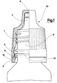
- the closure assembly of figure 1 comprises a cap assembly 10 applied on a container having a neck 9 and a dispenser 7.
- the cap assembly 10 is composed of two plastic parts, which are assembled on insertion of the whole cap assembly 10 into the container neck 9.
- Figure 1 shows the cap assembly 10 mounted on the container before the container has been opened for a first time.
- the cap assembly 10 comprises a first part constituted by a cap 1, which is generally used to reclose the container once it has been opened for the first time.
- the cap 1 is generally manufactured by pressing of plastic material and is provided with an internal thread which couples with an external thread provided on a container neck 9.
- the cap assembly 10 further comprises a second part, constituted by an annular element consisting of a ring 3 which when the cap assembly 10 is united joints into an annular seat fashioned in an internal wall of the cap 1.
- the annular element comprises a safety strip 4 coaxially connected with the ring 3 by means of easy-break struts 5, which when broken testify that the container has in fact been opened.
- the safety strip 4 is provided with a lip 12 destined to interact, when the cap 1 is unscrewed, with an annular protruberance 13 provided on the container neck 9.
- the cap 1 On first unscrewing, the cap 1 is raised and draws the ring 3 and the safety strip 4 with it for a certain distance, up until when the lip 12 of the safety strip 4 comes into contact with the protruberance 13 of the neck 9. As the unscrewing procedure continues, the struts 5 are stretched by traction in the opening direction of the cap 1 up until they break and the safety strip 4 detaches from the rest of the cap assembly 10.
- the first embodiment of the present closure assembly comprises a seal ring 6 fashioned from the plastic of the dispenser 7 neck and interacting with an internal lateral surface of the cap 1.
- the seal ring 6 provides a seal against the internal wall of the cap 1, at least when the cap 1 is moved axially upwards over distances which do not exceed a minimum displacement distance necessary for a detachment of the safety strip 4.
- the seal ring 6 exhibits an external diameter which is not only greater than the internal diameter of the contact zone, that is the annular portion of cap internal wall with which the seal ring 6 contacts when the cap assembly 10 is mounted on the container, but also greater than the maximum internal diameter presented by the tract of wall exhibited by the cap 1 immediately underlying the annular contact portion, which has an axial length that is at least equal to the minimum distance necessary to cause the struts 5 to break.
- the cap 1 comprises a seal zone on the internal lateral surface of the upper part of the cap 1 itself, (including the dispenser 7) which interacts with the seal ring 6 up to when the safety strip 4 breaks.
- the safety strip 4 connected to it lifts freely up to when the lip 12 contacts the protruberance 13 of the container neck 9.
- the seal zone of the cap 1 moves upwards, dragging on the seal ring 6 of the dispenser 7.
- the seal zone of the cap 1 loses contact with the seal ring 6 only when the cap 1 has been raised enough to break the struts 5.
- Isolation of the container can be achieved by means of a seal ring made not on the container but on the internal lateral surface of the cap 1.
- the seal ring will have a smaller internal diamter than the maximum diameter exhibited by a tract of external lateral wall on the dispenser 7. This tract, which will be axially longer than a minimum displacement necessary to break or distance the safety strip 4, will constitute a zone of the dispenser 7 on which the dragging of the safety strip 4 takes place.
- any deformable element can be used as a sealing means of the cap on the container, and will be interplaced between the external lateral surface of the dispenser 7 and the internal lateral surface of the upper part of the cap 1 covering said dispenser 7.
- the determining factor is that in each case the seal on the container should be maintained over axial displacements between the cap 1 and the container which must be at least as long as the minimum displacement of the cap 1 needed to break the safety strip 4.
- Figure 2 shows a closure assembly of the same type as the above-described assembly, comprising a plastic cap assembly 10' in which the detachment of the safety strip 4 occurs by unscrewing or raising the cap of the cap assembly 10' itself.
- the cap assembly 10' comprising a cap 1', is applied on a container neck 9' and a container dispenser 7', constituted in this case by a drop-counter solidly inserted into the neck 9' to enable drops of a liquid to be counted as they exit the container.
- a container dispenser 7' constituted in this case by a drop-counter solidly inserted into the neck 9' to enable drops of a liquid to be counted as they exit the container.
- the cap assembly 10' is shown mounted but as yet unopened.
- the dispenser 7' is cup-shaped and has a slightly larger external diameter than the internal diameter of the container mouth, which is forced against the internal walls of the neck 9'.
- the cup is superiorly provided with a flat annular crown which strikes against the upper surface of the container. On its bottom surface the cup exhibits a small central hole for a passage of liquid drop by drop, and a small internal tube for air entrance.
- the dispenser 7' further exhibits a coaxial cylindrical spout, arranged between the hole and the tube, fashioned on the bottom of the cup and facing externally of the container.
- a seal 8' on the lower face of the cap 1' seals against the flat annular crown and the spout of the dispenser 7'.
- the closure assembly of the present invention comprises an annular element 6' fashioned in relief on the internal lateral surface of the cup of the dispenser 7', and projecting inwards.
- the annular element 6' is arranged on the upper part of the cup and seals against the external lateral surface of a coaxial cylindrical element 11' fashioned on the seal 8'.
- the cylindrical element 11' faces inwardly of the cup and exhibits a greater external diameter than the internal diameter of the annular element 6'.
- the cap 10' On the external lateral surface of the cylindrical element 11', the cap 10' also comprises a seal zone arranged immediately below the annular zone, which comes into contact with the annular element 6' when the cap assembly 10' is mounted on the container.
- the seal zone is longer than the minimum displacement required to break the safety strip of the cap assembly 10'.
- This embodiment also offers the possibility of achieving perfect hermetic closure by means of a seal ring fashioned on the cap instead of on the container.
- the seal ring would be arranged on the external surface of the cylindrical element 11' of the seal 8'.
- the seal occurs between the external lateral surface of the cylindrical element 11' and the internal lateral surface of the dispenser 7', and is guaranteed for relative axial movement between the cap and the container over a distance that does not cause detachment of the safety strip.
Landscapes
- Engineering & Computer Science (AREA)
- Mechanical Engineering (AREA)
- Closures For Containers (AREA)
Applications Claiming Priority (2)
| Application Number | Priority Date | Filing Date | Title |
|---|---|---|---|
| ITMO930021U | 1993-07-26 | ||
| ITMO930021 IT233635Y1 (it) | 1993-07-26 | 1993-07-26 | Chiusura ermetica con capsula in plastica per contenitori dotati di erogatore. |
Publications (2)
| Publication Number | Publication Date |
|---|---|
| EP0636552A2 true EP0636552A2 (de) | 1995-02-01 |
| EP0636552A3 EP0636552A3 (de) | 1995-03-22 |
Family
ID=11385362
Family Applications (1)
| Application Number | Title | Priority Date | Filing Date |
|---|---|---|---|
| EP94830252A Withdrawn EP0636552A3 (de) | 1993-07-26 | 1994-05-26 | Schraubkappe mit abtrennbarem Sicherheitsabschnitt und Dichtungsring. |
Country Status (3)
| Country | Link |
|---|---|
| EP (1) | EP0636552A3 (de) |
| CA (1) | CA2117317C (de) |
| IT (1) | IT233635Y1 (de) |
Cited By (3)
| Publication number | Priority date | Publication date | Assignee | Title |
|---|---|---|---|---|
| FR2737193A1 (fr) * | 1995-07-24 | 1997-01-31 | Capshold Ci Limited | Ensemble compte-gouttes integre et capsule a vis monopiece en matiere synthetique avec bague temoin d'ouverture |
| EP4397597A1 (de) * | 2023-01-03 | 2024-07-10 | UAB Baltic caps | Verschlusskappe |
| EP4406872A1 (de) * | 2023-01-25 | 2024-07-31 | UAB Baltic caps | Verschlussvorrichtung |
Family Cites Families (3)
| Publication number | Priority date | Publication date | Assignee | Title |
|---|---|---|---|---|
| CH577919A5 (de) * | 1975-02-28 | 1976-07-30 | Wiedmer Walter Plastikform | |
| CH649057A5 (fr) * | 1982-06-10 | 1985-04-30 | Stericric Sa | Flacon pour liquides apte a supporter une sterilisation terminale, muni d'un dispositif de fermeture inviolable. |
| US5009323A (en) * | 1989-11-13 | 1991-04-23 | Sunbeam Plastics Corporation | Tamper indicating closure having a rotary seal |
-
1993
- 1993-07-26 IT ITMO930021 patent/IT233635Y1/it active IP Right Grant
-
1994
- 1994-05-26 EP EP94830252A patent/EP0636552A3/de not_active Withdrawn
- 1994-06-09 CA CA 2117317 patent/CA2117317C/en not_active Expired - Fee Related
Cited By (3)
| Publication number | Priority date | Publication date | Assignee | Title |
|---|---|---|---|---|
| FR2737193A1 (fr) * | 1995-07-24 | 1997-01-31 | Capshold Ci Limited | Ensemble compte-gouttes integre et capsule a vis monopiece en matiere synthetique avec bague temoin d'ouverture |
| EP4397597A1 (de) * | 2023-01-03 | 2024-07-10 | UAB Baltic caps | Verschlusskappe |
| EP4406872A1 (de) * | 2023-01-25 | 2024-07-31 | UAB Baltic caps | Verschlussvorrichtung |
Also Published As
| Publication number | Publication date |
|---|---|
| CA2117317C (en) | 2000-09-19 |
| IT233635Y1 (it) | 2000-02-01 |
| ITMO930021U1 (it) | 1995-01-26 |
| EP0636552A3 (de) | 1995-03-22 |
| ITMO930021V0 (it) | 1993-07-26 |
| CA2117317A1 (en) | 1995-01-27 |
Similar Documents
| Publication | Publication Date | Title |
|---|---|---|
| US4700860A (en) | Tamper indicating vacuum package | |
| US4403709A (en) | Drinking and pouring aid for containers of beverages and other liquids | |
| US4746035A (en) | Liquid dispenser having a tamperproof overcap | |
| EP0807058B1 (de) | Ausgiessvorrichtung mit herausnehmbarer membran | |
| US4487326A (en) | Carbonated beverage package | |
| US4625875A (en) | Tamper-evident closure | |
| US3460701A (en) | Composite closure | |
| US4795065A (en) | Spout for packaging containers | |
| US4653676A (en) | Captive cap construction for hand-held dispenser | |
| US4561553A (en) | Snap on twist off tamper-proof closure for containers | |
| US4305517A (en) | Tamperproof closure | |
| US4526279A (en) | Severing overcap for container | |
| EP0194068B1 (de) | Flaschen | |
| CA1154402A (en) | Tamper indicating cork | |
| US5123555A (en) | Container cap having external bead | |
| US2991913A (en) | Combined pouring and sealing devices for containers | |
| EP0168891B1 (de) | Zusammenstellung für Flaschen bestehend aus einer Kappe, einer Tropfvorrichtung und einem Ring | |
| US4523689A (en) | Reusable tamper-proof container | |
| US4109816A (en) | Plastic cap for bottle | |
| US3985255A (en) | Bottle cap | |
| US2887240A (en) | Insertable closure for bottles and like containers | |
| US2662669A (en) | Dispensing container and slitted resilient valve therefor | |
| CA2117317C (en) | A hermetic closure in a cap assembly for containers equipped with dispenser devices | |
| WO2000075020A2 (en) | Storage of beverages | |
| GB2258860A (en) | Valved closure |
Legal Events
| Date | Code | Title | Description |
|---|---|---|---|
| PUAI | Public reference made under article 153(3) epc to a published international application that has entered the european phase |
Free format text: ORIGINAL CODE: 0009012 |
|
| AK | Designated contracting states |
Kind code of ref document: A2 Designated state(s): AT BE CH DE DK ES FR GB GR IE LI LU MC NL PT SE |
|
| PUAL | Search report despatched |
Free format text: ORIGINAL CODE: 0009013 |
|
| AK | Designated contracting states |
Kind code of ref document: A3 Designated state(s): AT BE CH DE DK ES FR GB GR IE LI LU MC NL PT SE |
|
| STAA | Information on the status of an ep patent application or granted ep patent |
Free format text: STATUS: THE APPLICATION IS DEEMED TO BE WITHDRAWN |
|
| 18D | Application deemed to be withdrawn |
Effective date: 19950809 |