EP0636729B1 - Verfahren zur Herstellung von Strumpfwaren und Strick- und Nähmaschinen - Google Patents
Verfahren zur Herstellung von Strumpfwaren und Strick- und Nähmaschinen Download PDFInfo
- Publication number
- EP0636729B1 EP0636729B1 EP94111633A EP94111633A EP0636729B1 EP 0636729 B1 EP0636729 B1 EP 0636729B1 EP 94111633 A EP94111633 A EP 94111633A EP 94111633 A EP94111633 A EP 94111633A EP 0636729 B1 EP0636729 B1 EP 0636729B1
- Authority
- EP
- European Patent Office
- Prior art keywords
- hosiery
- stitching
- chains
- trim
- knitting
- Prior art date
- Legal status (The legal status is an assumption and is not a legal conclusion. Google has not performed a legal analysis and makes no representation as to the accuracy of the status listed.)
- Expired - Lifetime
Links
- 238000009940 knitting Methods 0.000 title abstract description 34
- 238000000034 method Methods 0.000 title abstract description 10
- 238000004519 manufacturing process Methods 0.000 title abstract 2
- 210000003371 toe Anatomy 0.000 claims abstract description 34
- 230000014759 maintenance of location Effects 0.000 claims description 12
- 238000011144 upstream manufacturing Methods 0.000 claims description 4
- 230000001360 synchronised effect Effects 0.000 claims description 2
- 238000012546 transfer Methods 0.000 claims description 2
- 239000002699 waste material Substances 0.000 abstract description 8
- 210000000453 second toe Anatomy 0.000 abstract description 2
- 238000009966 trimming Methods 0.000 description 10
- 229920000742 Cotton Polymers 0.000 description 6
- 238000003780 insertion Methods 0.000 description 5
- 230000037431 insertion Effects 0.000 description 5
- 210000002683 foot Anatomy 0.000 description 3
- 230000000694 effects Effects 0.000 description 2
- 239000000700 radioactive tracer Substances 0.000 description 2
- 230000002441 reversible effect Effects 0.000 description 2
- 238000009941 weaving Methods 0.000 description 2
- 230000005540 biological transmission Effects 0.000 description 1
- 239000003086 colorant Substances 0.000 description 1
- 238000007796 conventional method Methods 0.000 description 1
- 238000012937 correction Methods 0.000 description 1
- 239000004744 fabric Substances 0.000 description 1
- 239000012467 final product Substances 0.000 description 1
- 210000000474 heel Anatomy 0.000 description 1
- 238000011031 large-scale manufacturing process Methods 0.000 description 1
- 230000000670 limiting effect Effects 0.000 description 1
- 230000001681 protective effect Effects 0.000 description 1
- 239000004753 textile Substances 0.000 description 1
Images


Classifications
-
- D—TEXTILES; PAPER
- D05—SEWING; EMBROIDERING; TUFTING
- D05B—SEWING
- D05B23/00—Sewing apparatus or machines not otherwise provided for
- D05B23/007—Sewing units for assembling parts of knitted panties or closing the stocking toe part
-
- D—TEXTILES; PAPER
- D04—BRAIDING; LACE-MAKING; KNITTING; TRIMMINGS; NON-WOVEN FABRICS
- D04B—KNITTING
- D04B1/00—Weft knitting processes for the production of fabrics or articles not dependent on the use of particular machines; Fabrics or articles defined by such processes
- D04B1/22—Weft knitting processes for the production of fabrics or articles not dependent on the use of particular machines; Fabrics or articles defined by such processes specially adapted for knitting goods of particular configuration
- D04B1/24—Weft knitting processes for the production of fabrics or articles not dependent on the use of particular machines; Fabrics or articles defined by such processes specially adapted for knitting goods of particular configuration wearing apparel
- D04B1/26—Weft knitting processes for the production of fabrics or articles not dependent on the use of particular machines; Fabrics or articles defined by such processes specially adapted for knitting goods of particular configuration wearing apparel stockings
-
- D—TEXTILES; PAPER
- D05—SEWING; EMBROIDERING; TUFTING
- D05B—SEWING
- D05B23/00—Sewing apparatus or machines not otherwise provided for
- D05B23/007—Sewing units for assembling parts of knitted panties or closing the stocking toe part
- D05B23/009—Toe closers
-
- D—TEXTILES; PAPER
- D05—SEWING; EMBROIDERING; TUFTING
- D05D—INDEXING SCHEME ASSOCIATED WITH SUBCLASSES D05B AND D05C, RELATING TO SEWING, EMBROIDERING AND TUFTING
- D05D2305/00—Operations on the work before or after sewing
- D05D2305/08—Cutting the workpiece
- D05D2305/10—Cutting the workpiece longitudinally
-
- Y—GENERAL TAGGING OF NEW TECHNOLOGICAL DEVELOPMENTS; GENERAL TAGGING OF CROSS-SECTIONAL TECHNOLOGIES SPANNING OVER SEVERAL SECTIONS OF THE IPC; TECHNICAL SUBJECTS COVERED BY FORMER USPC CROSS-REFERENCE ART COLLECTIONS [XRACs] AND DIGESTS
- Y02—TECHNOLOGIES OR APPLICATIONS FOR MITIGATION OR ADAPTATION AGAINST CLIMATE CHANGE
- Y02P—CLIMATE CHANGE MITIGATION TECHNOLOGIES IN THE PRODUCTION OR PROCESSING OF GOODS
- Y02P70/00—Climate change mitigation technologies in the production process for final industrial or consumer products
- Y02P70/50—Manufacturing or production processes characterised by the final manufactured product
- Y02P70/62—Manufacturing or production processes characterised by the final manufactured product related technologies for production or treatment of textile or flexible materials or products thereof, including footwear
-
- Y—GENERAL TAGGING OF NEW TECHNOLOGICAL DEVELOPMENTS; GENERAL TAGGING OF CROSS-SECTIONAL TECHNOLOGIES SPANNING OVER SEVERAL SECTIONS OF THE IPC; TECHNICAL SUBJECTS COVERED BY FORMER USPC CROSS-REFERENCE ART COLLECTIONS [XRACs] AND DIGESTS
- Y10—TECHNICAL SUBJECTS COVERED BY FORMER USPC
- Y10T—TECHNICAL SUBJECTS COVERED BY FORMER US CLASSIFICATION
- Y10T83/00—Cutting
- Y10T83/202—With product handling means
- Y10T83/2074—Including means to divert one portion of product from another
- Y10T83/2087—Diverging product movers
-
- Y—GENERAL TAGGING OF NEW TECHNOLOGICAL DEVELOPMENTS; GENERAL TAGGING OF CROSS-SECTIONAL TECHNOLOGIES SPANNING OVER SEVERAL SECTIONS OF THE IPC; TECHNICAL SUBJECTS COVERED BY FORMER USPC CROSS-REFERENCE ART COLLECTIONS [XRACs] AND DIGESTS
- Y10—TECHNICAL SUBJECTS COVERED BY FORMER USPC
- Y10T—TECHNICAL SUBJECTS COVERED BY FORMER US CLASSIFICATION
- Y10T83/00—Cutting
- Y10T83/202—With product handling means
- Y10T83/2092—Means to move, guide, or permit free fall or flight of product
- Y10T83/2192—Endless conveyor
-
- Y—GENERAL TAGGING OF NEW TECHNOLOGICAL DEVELOPMENTS; GENERAL TAGGING OF CROSS-SECTIONAL TECHNOLOGIES SPANNING OVER SEVERAL SECTIONS OF THE IPC; TECHNICAL SUBJECTS COVERED BY FORMER USPC CROSS-REFERENCE ART COLLECTIONS [XRACs] AND DIGESTS
- Y10—TECHNICAL SUBJECTS COVERED BY FORMER USPC
- Y10T—TECHNICAL SUBJECTS COVERED BY FORMER US CLASSIFICATION
- Y10T83/00—Cutting
- Y10T83/869—Means to drive or to guide tool
- Y10T83/8798—With simple oscillating motion only
- Y10T83/8804—Tool driver movable relative to tool support
- Y10T83/8805—Cam or eccentric revolving about fixed axis
Definitions
- the present invention relates to the textile field and more specifically relates to toe stitching machines for hosiery items such as socks, stockings, pop socks and the like.
- Hosiery items such as socks, stockings, pop socks and the like, hereinafter generically termed “hosiery”, are currently knitted mainly by means of high-speed circular machines, for example similar to a machine disclosed in GB-A-1 078 462, starting from the top down to the toe or vice versa.
- These machines have electronic or mechanical programming that controls the relative movements of needles, hooks, thread guides and other components and elements of the machine in order to obtain different kinds of knitting according to the different effects to be provided on the item of hosiery.
- a hosiery item such as a sock is currently manufactured by knitting the following portions in succession: double top, body, heel, foot, and toe.
- a few rows of "trim”, i.e. rows with very loose stitches, are usually knitted after the toe, followed by a thicker trimming and by a hemstitch. At this point the thread guides are raised and the threads are cut.
- the hosiery items When knitting ends, the hosiery items still have a tubular shape which is open at the level of the toe, and it is necessary to stitch this toe; this stitching is currently often performed with automatic stitching machines that require an operator to load the hosiery items manually one by one.
- Chain means move the hosiery items towards heads for cutting the waste constituted by the hemstitch, by the trimming and by part of the trim rows, and stitch the open toe so that the hosiery items have perfectly and uniformly closed toes.
- the presence of the trimming after the trim rows has the purpose of ensuring correction insertion on the guide, although it entails a waste of thread which is hardly negligible for large-scale productions such as those normally occurring in this sector. Furthermore, the incidence of the time wasted by the operator to fit each hosiery item on the stitching machine on the cost of each hosiery item is very important, since this operation currently cannot be automated.
- Some toe stitching machines such as for example those manufactured by the United States company Detexomat, instead fit the hosiery items on tubular guides, from which they are then picked up by traction means that take them to be stitched. With these machines the positioning time of the operator is shorter, but the waste of thread is significantly higher, as the hosiery items need a double trimming after the trim rows and in any case still require that one hosiery item at a time be loaded.
- a principal aim of the present invention is to provide a stitching machine for stitching toes of hosiery items, such as socks, stockings, pop socks and the like, which allows to overcome the drawbacks described above: in other words, to considerably increase productivity and almost completely eliminate the waste of excess thread required for toe stitching operations.
- An object of the invention is to provide an improved or modified stitching machine for stitching the toes of hosiery items so as to allow said considerable increase in productivity and savings in terms of thread waste as well as savings on general consumption and lower wear, caused by each manufactured item, to which the machines are subjected.
- a stitching machine which comprises two independent stitching units which are fed by a common conveyor that has an inlet guide in which a row of stitches, interposed between mutually joined first and second hosiery items, engages. There are also means for cutting said row of stitches and traction means which are suitable to move the first and second hosiery items towards said cutting means and then, along separate paths, towards said two independent stitching units.
- a modified circular knitting machine may be employed to provide the mutually joined first and second hosiery items, with mechanical programming based on a drum whose lateral surface is used through 360° of its extension with cams for the actuation of knitting elements, has the characteristic that said lateral surface is substantially engaged over the first 180° by cams which are suitable to weave said first hosiery item and substantially over the second 180° by cams which are suitable to knit the second hosiery item.
- a first hosiery item 1 has been knitted starting from a double top 2 made of elastic thread and cotton, subsequently continuing with a body 3 made of cotton and helanca, with a heel 4 made of terry cloth or towelling, with a foot 5 made of towelling, cotton and helanca with a towelling gusset 6 on the toe 7.
- some helanca trim rows 8 have been knitted, subsequently continuing with a second toe 17 with a second towelling gusset 16, with a second foot 15 with a second heel 14, a second body 13, and a second double top 12, thus forming a second hosiery item 10.
- the top-to-top knitting method described above has allowed to obtain a first hosiery item 1 and a second hosiery item 10 which are joined by their toes 7 and 17 by means of the trim rows 8.
- the two steps for knitting the first hosiery item 1 and the second hosiery item 10, performed for example with a known circular machine modified as described hereafter, allow a considerable saving in terms of time, as the already described steps of the knitting of the two trimmings, as well as the downtimes for ending and removing the first hosiery item and starting the knitting of the second hosiery item, are eliminated.
- Said two steps furthermore allow saving in terms of waste of thread required to knit the trimmings, the hemstitches and a common trim row for the two hosiery items, as well as the other already mentioned savings.
- knitting according to the above described method is possible by means of a circular machine with mechanical programming based on a drum in which the cams, which have different shapes and lengths and are arranged along the entire lateral cylindrical surface of the drum of which figure 10 illustrates a spread, actuate the movements of the various knitting elements, such as thread guides for each different thread type, movements of needles, hooks and other auxiliary elements whose operation is certainly known to a technician in the field and therefore is not described in detail.
- the programming along the 360° arc of the spread of figure 10 the first 180° are dedicated to the knitting of the first hosiery item 1, and the second 180° are dedicated to the knitting of the second hosiery item 10.
- the circular machine is thus capable of knitting the two hosiery items 1 and 10 starting from the top 2 to the second top 12.
- the second hosiery item 10 is thus knitted in reverse with respect to the first hosiery item 1, but this reversal is inconsequential in terms of aesthetic differences or of different effects that can be noted by a person wearing both.
- the technique of knitting pantyhose, which are knitted toe-to-toe and in which the second body is formed in reverse with respect to the first one without this being evident to the wearer, is in fact well-known.
- the drum of the circular machine is divided into two parts which are substantially proportional to the number of elementary operations required to knit each one of the two hosiery items.
- the hosiery item must have lines and patterns, obtained by frequently swapping threads of different colors, on its body, the operations that in current machines used to be actuated along the full 360° arc by the cams provided on the drum are actuated, by using an auxiliary line forming unit, which is also of a known type and is already used in the field for similar purposes.
- the line forming unit is used for example to produce colored bands in the upper part of the body or to produce patterns.
- FIG. 14 As regards the top-to-top knitting of stockings and pop socks, as mechanically-programmed circular machines are currently unable to perform knitting with oppositely arranged tapers as shown in figures 5 and 6, there is a special cam 49 which is shown in figure 14.
- Said cam has a substantially heart-shaped profile 5G which comprises a shallower portion 50a and two higher portions 50b. The axis of the cam passes at the midpoint between the shallower portion 50a and the recess 51 provided between the two higher portions 50b.
- the weaving elements are actuated by a tracer, not shown, that follows the profile 50, actuating the knitting cams, which produce a gradual tapering and widening in knitting the body 3 and the body 13, respectively, of the hosiery item 1 and of the hosiery item 10.
- top-to-top knitting can of course be obtained easily by means of programming that any technician is capable of performing.
- a modified stitching machine comprises a feed table 30 at which there is a conveyor 31 that comprises a guide 32 in which the rows of trim 8 engage, with a hosiery item 1 and a hosiery item 10 arranged respectively on the sides of said guide.
- the conveyor 31 moves the hosiery items 1 and 10 towards a cutter 33 in which they are separated and then advanced along separate paths towards conveyors 34 and 35 that belong respectively to independent stitching units 36 and 37 of a type that has been known for decades in the field and is currently marketed by various companies, some of which have been mentioned in the introduction.
- the operator has no difficulty in stretching the hosiery items 1 and 10 respectively with his right and left hands and in inserting them in the guide 32 of the conveyor 31.
- the time required for these insertion operations is in fact much shorter than the time currently taken by an operator to insert a single hosiery item in the guides of a conventional stitching machine, since as described he must manually stretch the hemstitch and the trimming that have curled at the end of the stitching step and carefully insert the trim rows in said guide.
- the time saved by the operator in insertion can be advantageously used to insert another pair of hosiery items 1 and 10 on a similar stitching machine modified according to the invention with a second conveyor 31 that converges onto the same feed table 30.
- the productivity of a single operator assigned to feeding the toe stitching machines is multiplied by four with respect to the conventional method.
- there is a significant advantage in terms of thread saving as the waste previously indispensable to knit the trimmings that had to be subsequently eliminated together with the hemstitches is avoided.
- a conveyor 31 is shown in detail and comprises a toothed chain 40 which is suitable to engage in the trim rows provided between the hosiery items 1 and 10, not shown here, and to move them towards the cutter 33 driven by an eccentric element 41 which moves in step with the chain 40 by means of a transmission belt 42.
- the eccentric element 41 actuates a blade 43 which moves in a reciprocating manner with respect to a counter-blade 44 which is rigidly coupled to a frame 45 from which the conveyors 34 and 35 diverge.
- the trim rows 8, in addition to having the simple shape shown in figure 11, in which they are constituted by rows of helanca stitches 46, may also have the shape shown in figures 12 and 13. More precisely, in figure 12 they are formed by a series of cotton rows 47 which is interposed between two series of helanca rows 46 which are adjacent to the toes 7 and 17, whereas in figure 13 they are formed by a series of rows of helanca stitches 48 interposed between two series of rows of cotton stitches 47 which are in turn interposed between two series of rows of helanca stitches 46 which are adjacent to the toes 7 and 17. Cotton can in fact be easily engaged by the conveyors, but helanca is inserted more easily between the guides of the stitching machines.
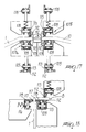
- Figures 15 to 20 illustrate another embodiment of the conveyor and of the means for causing the advancement of the hosiery items to feed two known stitching units, each of which has a feeder which is constituted by a pair of chains 103 and 104 which face each other along a vertical plane with one of their portions in order to retain in a substantially vertical plane the toe of the hosiery item 1 and 10 which is to be stitched.
- a feeder which is constituted by a pair of chains 103 and 104 which face each other along a vertical plane with one of their portions in order to retain in a substantially vertical plane the toe of the hosiery item 1 and 10 which is to be stitched.
- the conveyor comprises an inlet guide 105 on which the operator places the two hosiery items 1 and 10, joined at the toe, stretching them so as to widen the row of trim 8 that joins them.
- each pair comprises an upper chain 108 and a lower chain 109 which face each other with one of their portions at the horizontal feed table 110 on which the hosiery items are placed by the operator.
- the upper chain 108 and the lower chain 109 are provided with first retention means which engage one of the two hosiery items at the trim row 8 to clamp it parallel to the feed table 110.
- the two pairs of chains 107a and 107b are arranged side by side along the advancement direction 106, and the cutting means 111 are arranged between the two pairs of chains 107a and 107b proximate to their beginning.
- the cutting means 111 can be constituted by a cutter of the type described with reference to figures 8 and 9, whose actuation is synchronized with the actuation of the chains 107a and 107b.
- the first retention means are constituted by serrations 112 which are formed by plates 113 that are applied to the links of the chains 108 and 109 and are arranged on a plane that is substantially at right angles to the feed table 110.
- the feed table 110 has, downstream of the cutting means along the advancement direction 106, two lateral recesses 114 and 115, one for each pair of chains 107a and 107b, so that the related hosiery item 1 and 10 drops with its portion located outside the chains 108 and 109 and arranges itself vertically.
- the lower chain 109 of each pair of chains 107a or 107b has a final portion that extends beyond the related upper chain 108 and is provided with second hosiery item retention means that cooperate with second retention means mounted on an auxiliary chain 116 which is arranged laterally with respect to the lower chain 109.
- Said second retention means are constituted, like the first retention means, by serrations 117 formed by plates 118 applied to the links of the chains 109 and 116. Differently from the serrations 112, the serrations 117 are arranged, on the portions of the chains 109 and 116 that face each other, on a plane which is parallel to the feed table 110 so as to clamp the hosiery item 1, 10 proximate to the toe 7, 17 on a substantially vertical plane.
- the upper chain 108, the lower chain 109, and the auxiliary chain 116 may be replaced with a pair of chains, not shown for the sake of simplicity, which have serrations for retaining the hosiery item and extend along a helical path to transfer the hosiery item from the horizontal position, on the feed table 110, to the vertical position directly upstream of the chains 103 and 104 of the feeder of the related stitching unit.
- modified stitching machine according to the invention can be altered and/or modified without thereby abandoning the protective scope of said invention as defined in the appended claims.
Landscapes
- Engineering & Computer Science (AREA)
- Textile Engineering (AREA)
- Treatment Of Fiber Materials (AREA)
- Sewing Machines And Sewing (AREA)
- Socks And Pantyhose (AREA)
- Knitting Machines (AREA)
Claims (9)
- Nähmaschine zum Nähen der Zehenteile von Bund zu Bund gestrickter Strumpfwaren, gekennzeichnet durch zwei unabhängige Näheinheiten (36, 37), welche von einem gemeinsamen Förderer (31) gespeist werden, der eine Einlaßführung (32; 105) hat, mit der ein zwischen einer ersten und einer zweiten miteinander verbundenen Strumpfware liegender Saum in Eingriff kommt, mit Mitteln (33, 111) zum Schneiden des Saums und Transporten (34, 35, 107a, 107b) zum Führen der ersten und der zweiten Strumpfware zu den Schneidemitteln und anschließend entlang getrennter Wege zu den beiden unabhängigen Näheinheiten.
- Maschine nach Anspruch 1, dadurch gekennzeichnet, daß die Mittel zum Schneiden des Saums eine Schneidevorrichtung mit einer Klinge (43) enthalten, die durch ein exzentrisches Element (41) betätigt wird, welches in Bezug auf eine feste, starr mit einem Stützrahmen (45) des Förderers gekoppelte Gegenklinge schwingt, daß die Transporte eine erste, in den Förder innen eingreifende Zahnkette (40) und zwei zusätzliche, stromabwärts der Schneidevorrichtung befindliche Förderer (34, 35) enthalten, welche zum Ergreifen der Zehenteile der Strumpfwaren geeignet sind und diese entlang getrennter Wege zu den unabhängigen Näheinheiten führen.
- Maschine nach Anspruch 1, dadurch gekennzeichnet, daß die Transporte stromabwärts der Einlaßführung entlang der Vorschubrichtung (106) der Strumpfwaren in Richtung der Näheinheiten zwei Kettenpaare (107a, 107b) enthalten mit jeweils einer oberen Kette (108) und einer unteren Kette (109), die in einem ihrer Abschnitte an einem horizontalen Tisch (110) einander gegenüber liegen zwecks Zuführung zweier durch den Saum verbundener Strumpfwaren, daß die obere und die untere Kette mit ersten Haltemitteln (112, 113) versehen ist, die eine der beiden Strumpfwaren nahe des Saums ergreifen, um diese parallel zum Zuführtisch zu verklemmen, und daß die beiden Kettenpaare entlang der Vorschubrichtung einander gegenüber liegen und die Schneidemittel (111) zwischen den beiden Kettenpaaren angeordnet sind.
- Maschine nach Anspruch 3, dadurch gekennzeichnet, daß die ersten Haltemittel an den Gelenken der Ketten angebrachte und weitgehend rechtwinklig zum Zuführtisch angeordnete Zacken (112) enthalten.
- Maschine nach einem oder mehreren der vorhergehenden Ansprüche 3-4, dadurch gekennzeichnet, daß die Schneidemittel eine mit der Vorschubbewegung der Ketten synchron arbeitende Schneidevorrichtung enthalten.
- Maschine nach einem oder mehreren der vorhergehenden Ansprüche 3-5, dadurch gekennzeichnet, daß der Zuführtisch stromabwärts der Schneidemittel entlang der Vorschubrichtung zwei seitliche Aussparungen (114, 115) zum senkrechten Fallen des außerhalb der Ketten liegenden Abschnitts der Strumpfwaren hat, daß die untere Kette (109) jedes Kettenpaares einen Endabschnitt hat, der über die zugehörige obere Kette hinausgeht und mit zweiten Strumpfwarenhaltemitteln (117,118) versehen ist, welche mit zweiten Strumpfwarenhaltemitteln (117, 118) zusammenarbeiten, die auf einer quer zur unteren Kette angeordneten Hilfskette (116) zum Verklemmen der betreffenden Strumpfware in einer weitgehend senkrechten Ebene stromaufwärts der betreffenden Näheinheit befestigt sind.
- Maschine nach Anspruch 6, dadurch gekennzeichnet, daß die zweiten Haltemittel an den Gelenken der unteren Kette und der Hilfskette angebrachte und weitgehend parallel zum Zuführtisch angeordnete Zacken (117) enthalten.
- Maschine nach einem oder mehreren der vorhergehenden Ansprüche 6-7, dadurch gekennzeichnet, daß eine Führung (119) zum Richten des Abschnittes der betreffenden, zwischen den zweiten Haltemitteln und dem Saum liegenden Strumpfware stromabwärts der oberen Kette entlang der Vorschubrichtung zwischen der unteren Kette und der Hilfskette angeordnet ist zwecks Ausrichtung des Abschnittes der Strumpfware in einer weitgehend senkrechten Ebene stromaufwärts des Einlasses der betreffenden Näheinheit.
- Maschine nach einem oder mehreren der vorhergehenden Ansprüche 3-8, dadurch gekennzeichnet, daß die Ketten jedes Kettenpaares entlang eines spiraligen Weges verlaufen zwecks Transfer der betreffenden Strumpfware von einer weitgehend horizontalen Lage auf dem Zuführtisch in eine weitgehend vertikale Lage unmittelbar stromaufwärts der betreffenden Näheinheit.
Applications Claiming Priority (2)
| Application Number | Priority Date | Filing Date | Title |
|---|---|---|---|
| ITFI930151 | 1993-07-30 | ||
| ITFI930151A IT1262487B (it) | 1993-07-30 | 1993-07-30 | Metodo di fabbricazione di manufatti a calza, macchine modificate di tessitura e cucitura |
Publications (3)
| Publication Number | Publication Date |
|---|---|
| EP0636729A2 EP0636729A2 (de) | 1995-02-01 |
| EP0636729A3 EP0636729A3 (de) | 1995-04-19 |
| EP0636729B1 true EP0636729B1 (de) | 1998-12-02 |
Family
ID=11350572
Family Applications (1)
| Application Number | Title | Priority Date | Filing Date |
|---|---|---|---|
| EP94111633A Expired - Lifetime EP0636729B1 (de) | 1993-07-30 | 1994-07-26 | Verfahren zur Herstellung von Strumpfwaren und Strick- und Nähmaschinen |
Country Status (7)
| Country | Link |
|---|---|
| US (1) | US5555832A (de) |
| EP (1) | EP0636729B1 (de) |
| JP (1) | JPH07145503A (de) |
| AT (1) | ATE174079T1 (de) |
| DE (1) | DE69414927D1 (de) |
| ES (1) | ES2124344T3 (de) |
| IT (1) | IT1262487B (de) |
Families Citing this family (5)
| Publication number | Priority date | Publication date | Assignee | Title |
|---|---|---|---|---|
| IT1274234B (it) * | 1994-05-03 | 1997-07-15 | Andrea Conti | Macchina modificata per la cucitura di calze, calzini, gambaletti e simili |
| IT1271801B (it) * | 1994-12-27 | 1997-06-09 | Savio Macchine Spa | Dispositivo di trasporto ad una stazione finale di articoli tessili sfusi alimentati selettivamente da almeno due stazioni di alimentazione |
| ATE462316T1 (de) | 2002-07-03 | 2010-04-15 | Takeda Leg Wear Co Ltd | Socke |
| ITFI20070183A1 (it) * | 2007-08-02 | 2009-02-03 | Andrea Conti | "attrezzatura per elaborare manufatti doppi fra loro connessi e da separare per le successive rifinizioni |
| CN104988665B (zh) * | 2015-06-26 | 2017-08-29 | 浙江理工大学 | 一种丝袜罗口自动撑开装置及其控制方法 |
Family Cites Families (10)
| Publication number | Priority date | Publication date | Assignee | Title |
|---|---|---|---|---|
| GB528869A (en) * | 1939-05-16 | 1940-11-08 | Wildt & Co Ltd | Improvements in or relating to the production of knitted articles or pieces of fabric in string formation |
| CH406506A (fr) * | 1963-07-11 | 1966-01-31 | Bonneterie S A Et | Procédé de fabrication d'un vêtement tricoté, machine pour la mise en oeuvre de ce procédé et vêtement obtenu par ce procédé |
| US3407632A (en) * | 1966-11-15 | 1968-10-29 | Scott & Williams Inc | Knitted sweaters and methods of making the same |
| US3450075A (en) * | 1967-07-07 | 1969-06-17 | Martinsburg Mills Inc | Apparatus for closing the toe portion of circular knit hosiery |
| FR2202520A5 (de) * | 1973-10-08 | 1974-05-03 | Inst Textile De France | |
| FR2373976A1 (fr) * | 1976-12-16 | 1978-07-13 | Dim Rosy | Procede de production en continu d'articles de bonneterie tels que des chaussettes, bas et mi-bas et machine pour la mise en oeuvre du procede |
| US4147081A (en) * | 1977-08-25 | 1979-04-03 | Pellaton Roy C | Pasta noodle packaging apparatus and method |
| US4363251A (en) * | 1980-07-03 | 1982-12-14 | Jeno's Inc. | Method and apparatus for cutting bread |
| EP0149295B1 (de) * | 1984-01-19 | 1988-10-19 | Tomotake Nakahira | Vorrichtung zum Verarbeiten von rundgestrickten Maschenwaren |
| GB2214939B (en) * | 1988-02-19 | 1992-04-22 | Shima Seiki Mfg | Method of preventing the edge of knitted fabric from unravelling |
-
1993
- 1993-07-30 IT ITFI930151A patent/IT1262487B/it active IP Right Grant
-
1994
- 1994-07-26 ES ES94111633T patent/ES2124344T3/es not_active Expired - Lifetime
- 1994-07-26 DE DE69414927T patent/DE69414927D1/de not_active Expired - Lifetime
- 1994-07-26 US US08/279,865 patent/US5555832A/en not_active Expired - Fee Related
- 1994-07-26 AT AT94111633T patent/ATE174079T1/de active
- 1994-07-26 EP EP94111633A patent/EP0636729B1/de not_active Expired - Lifetime
- 1994-07-29 JP JP6179025A patent/JPH07145503A/ja not_active Withdrawn
Also Published As
| Publication number | Publication date |
|---|---|
| ITFI930151A0 (it) | 1993-07-30 |
| ES2124344T3 (es) | 1999-02-01 |
| EP0636729A3 (de) | 1995-04-19 |
| ATE174079T1 (de) | 1998-12-15 |
| ITFI930151A1 (it) | 1995-01-30 |
| DE69414927D1 (de) | 1999-01-14 |
| IT1262487B (it) | 1996-06-28 |
| JPH07145503A (ja) | 1995-06-06 |
| EP0636729A2 (de) | 1995-02-01 |
| US5555832A (en) | 1996-09-17 |
Similar Documents
| Publication | Publication Date | Title |
|---|---|---|
| US5081854A (en) | Process for manufacturing a semi-finished product with circular knitting machines, in particular for producing undershirts, one-piece body garments, briefs or the like | |
| PL174745B1 (pl) | Sposób wytwarzania dzianych spodenek | |
| EP0504412A1 (de) | Verfahren zum stricken von rundstrickwaren und damit erhaltene strickwaren. | |
| EP0636729B1 (de) | Verfahren zur Herstellung von Strumpfwaren und Strick- und Nähmaschinen | |
| US3159988A (en) | Hosiery footwear and method of making | |
| GB2117805A (en) | A method of producing a knitted product | |
| JP6709794B2 (ja) | 靴下を製造するために半仕上げ管状製品の軸方向端部で縫い合わせにより閉じられる半仕上げ管状製品を提供するための方法、及びこの方法で得られた半仕上げ管状製品 | |
| EP0387765B1 (de) | Verfahren zur Herstellung eines halbfertigen Produktes mittels Rundstrickmaschine mit unterschiedlicher Fadenzuführung, speziell zur Herstellung von Unterhemden, einteiliger Unterwäsche, Slips etc. | |
| US2296303A (en) | Art of seaming | |
| CZ284876B6 (cs) | Způsob výroby polotovaru na okrouhlém pletacím stroji | |
| EP1338690B1 (de) | Strickverfahren und hergestelltes Produkt | |
| EP0426030A2 (de) | Verfahren und Vorrichtung zur Herstellung von Mustern an Strümpfen auf Doppeltzylinder-Rundstrickmaschinen | |
| GB2138852A (en) | Knitting heels or toes of socks | |
| RU2734486C2 (ru) | Устройство и способ прошивки мыска кругловязаного изделия | |
| EA045893B1 (ru) | Кеттельная машина с усовершенствованной направляющей для выравнивания краев двух соединяемых деталей трикотажного изделия | |
| IT9020259A1 (it) | Procedimento perfezionato di preparazione per la cucitura della punta di calze ottenute con macchine circolari | |
| GB2031968A (en) | Improvements in or relating to making knitted articles | |
| JPH0655961B2 (ja) | 靴下の編成方法 | |
| JPS6139428B2 (de) | ||
| HU186193B (en) | Method and apparatus for knitting sock respectively stocking formed by closed toe part and heel solution on flat-bed knitter of weft system |
Legal Events
| Date | Code | Title | Description |
|---|---|---|---|
| PUAI | Public reference made under article 153(3) epc to a published international application that has entered the european phase |
Free format text: ORIGINAL CODE: 0009012 |
|
| AK | Designated contracting states |
Kind code of ref document: A2 Designated state(s): AT BE CH DE DK ES FR GB GR IT LI NL PT SE |
|
| PUAL | Search report despatched |
Free format text: ORIGINAL CODE: 0009013 |
|
| AK | Designated contracting states |
Kind code of ref document: A3 Designated state(s): AT BE CH DE DK ES FR GB GR IT LI NL PT SE |
|
| 17P | Request for examination filed |
Effective date: 19950415 |
|
| 17Q | First examination report despatched |
Effective date: 19961213 |
|
| GRAG | Despatch of communication of intention to grant |
Free format text: ORIGINAL CODE: EPIDOS AGRA |
|
| GRAG | Despatch of communication of intention to grant |
Free format text: ORIGINAL CODE: EPIDOS AGRA |
|
| GRAH | Despatch of communication of intention to grant a patent |
Free format text: ORIGINAL CODE: EPIDOS IGRA |
|
| GRAH | Despatch of communication of intention to grant a patent |
Free format text: ORIGINAL CODE: EPIDOS IGRA |
|
| GRAA | (expected) grant |
Free format text: ORIGINAL CODE: 0009210 |
|
| AK | Designated contracting states |
Kind code of ref document: B1 Designated state(s): AT BE CH DE DK ES FR GB GR IT LI NL PT SE |
|
| PG25 | Lapsed in a contracting state [announced via postgrant information from national office to epo] |
Ref country code: NL Free format text: LAPSE BECAUSE OF FAILURE TO SUBMIT A TRANSLATION OF THE DESCRIPTION OR TO PAY THE FEE WITHIN THE PRESCRIBED TIME-LIMIT Effective date: 19981202 Ref country code: LI Free format text: LAPSE BECAUSE OF FAILURE TO SUBMIT A TRANSLATION OF THE DESCRIPTION OR TO PAY THE FEE WITHIN THE PRESCRIBED TIME-LIMIT Effective date: 19981202 Ref country code: GR Free format text: LAPSE BECAUSE OF NON-PAYMENT OF DUE FEES Effective date: 19981202 Ref country code: FR Free format text: LAPSE BECAUSE OF FAILURE TO SUBMIT A TRANSLATION OF THE DESCRIPTION OR TO PAY THE FEE WITHIN THE PRESCRIBED TIME-LIMIT Effective date: 19981202 Ref country code: CH Free format text: LAPSE BECAUSE OF FAILURE TO SUBMIT A TRANSLATION OF THE DESCRIPTION OR TO PAY THE FEE WITHIN THE PRESCRIBED TIME-LIMIT Effective date: 19981202 Ref country code: BE Free format text: LAPSE BECAUSE OF FAILURE TO SUBMIT A TRANSLATION OF THE DESCRIPTION OR TO PAY THE FEE WITHIN THE PRESCRIBED TIME-LIMIT Effective date: 19981202 Ref country code: AT Free format text: LAPSE BECAUSE OF FAILURE TO SUBMIT A TRANSLATION OF THE DESCRIPTION OR TO PAY THE FEE WITHIN THE PRESCRIBED TIME-LIMIT Effective date: 19981202 |
|
| REF | Corresponds to: |
Ref document number: 174079 Country of ref document: AT Date of ref document: 19981215 Kind code of ref document: T |
|
| REG | Reference to a national code |
Ref country code: CH Ref legal event code: EP |
|
| REF | Corresponds to: |
Ref document number: 69414927 Country of ref document: DE Date of ref document: 19990114 |
|
| REG | Reference to a national code |
Ref country code: ES Ref legal event code: FG2A Ref document number: 2124344 Country of ref document: ES Kind code of ref document: T3 |
|
| ITF | It: translation for a ep patent filed | ||
| PG25 | Lapsed in a contracting state [announced via postgrant information from national office to epo] |
Ref country code: SE Free format text: LAPSE BECAUSE OF FAILURE TO SUBMIT A TRANSLATION OF THE DESCRIPTION OR TO PAY THE FEE WITHIN THE PRESCRIBED TIME-LIMIT Effective date: 19990302 Ref country code: PT Free format text: LAPSE BECAUSE OF FAILURE TO SUBMIT A TRANSLATION OF THE DESCRIPTION OR TO PAY THE FEE WITHIN THE PRESCRIBED TIME-LIMIT Effective date: 19990302 Ref country code: DK Free format text: LAPSE BECAUSE OF FAILURE TO SUBMIT A TRANSLATION OF THE DESCRIPTION OR TO PAY THE FEE WITHIN THE PRESCRIBED TIME-LIMIT Effective date: 19990302 |
|
| PG25 | Lapsed in a contracting state [announced via postgrant information from national office to epo] |
Ref country code: DE Free format text: LAPSE BECAUSE OF FAILURE TO SUBMIT A TRANSLATION OF THE DESCRIPTION OR TO PAY THE FEE WITHIN THE PRESCRIBED TIME-LIMIT Effective date: 19990303 |
|
| EN | Fr: translation not filed | ||
| NLV1 | Nl: lapsed or annulled due to failure to fulfill the requirements of art. 29p and 29m of the patents act | ||
| REG | Reference to a national code |
Ref country code: CH Ref legal event code: PL |
|
| PGFP | Annual fee paid to national office [announced via postgrant information from national office to epo] |
Ref country code: GB Payment date: 19990721 Year of fee payment: 6 |
|
| PGFP | Annual fee paid to national office [announced via postgrant information from national office to epo] |
Ref country code: ES Payment date: 19990730 Year of fee payment: 6 |
|
| PLBE | No opposition filed within time limit |
Free format text: ORIGINAL CODE: 0009261 |
|
| STAA | Information on the status of an ep patent application or granted ep patent |
Free format text: STATUS: NO OPPOSITION FILED WITHIN TIME LIMIT |
|
| 26N | No opposition filed | ||
| PG25 | Lapsed in a contracting state [announced via postgrant information from national office to epo] |
Ref country code: GB Free format text: LAPSE BECAUSE OF NON-PAYMENT OF DUE FEES Effective date: 20000726 |
|
| PG25 | Lapsed in a contracting state [announced via postgrant information from national office to epo] |
Ref country code: ES Free format text: LAPSE BECAUSE OF NON-PAYMENT OF DUE FEES Effective date: 20000727 |
|
| GBPC | Gb: european patent ceased through non-payment of renewal fee |
Effective date: 20000726 |
|
| REG | Reference to a national code |
Ref country code: ES Ref legal event code: FD2A Effective date: 20010810 |
|
| PG25 | Lapsed in a contracting state [announced via postgrant information from national office to epo] |
Ref country code: IT Free format text: LAPSE BECAUSE OF NON-PAYMENT OF DUE FEES Effective date: 20050726 |