EP0636772B1 - Moteur à combustion interne - Google Patents
Moteur à combustion interne Download PDFInfo
- Publication number
- EP0636772B1 EP0636772B1 EP94108440A EP94108440A EP0636772B1 EP 0636772 B1 EP0636772 B1 EP 0636772B1 EP 94108440 A EP94108440 A EP 94108440A EP 94108440 A EP94108440 A EP 94108440A EP 0636772 B1 EP0636772 B1 EP 0636772B1
- Authority
- EP
- European Patent Office
- Prior art keywords
- oil
- cylinder
- combustion engine
- internal combustion
- line
- Prior art date
- Legal status (The legal status is an assumption and is not a legal conclusion. Google has not performed a legal analysis and makes no representation as to the accuracy of the status listed.)
- Expired - Lifetime
Links
- 238000002485 combustion reaction Methods 0.000 title claims abstract description 42
- 238000001816 cooling Methods 0.000 claims abstract description 65
- 238000010438 heat treatment Methods 0.000 claims description 26
- 239000000155 melt Substances 0.000 claims description 6
- 230000001050 lubricating effect Effects 0.000 claims description 5
- 238000011144 upstream manufacturing Methods 0.000 claims 1
- 238000005461 lubrication Methods 0.000 abstract description 10
- 239000003921 oil Substances 0.000 description 99
- 238000002844 melting Methods 0.000 description 13
- 230000008018 melting Effects 0.000 description 13
- 239000010687 lubricating oil Substances 0.000 description 3
- 239000007921 spray Substances 0.000 description 3
- 239000003344 environmental pollutant Substances 0.000 description 1
- 230000002349 favourable effect Effects 0.000 description 1
- 239000000446 fuel Substances 0.000 description 1
- 238000003780 insertion Methods 0.000 description 1
- 230000037431 insertion Effects 0.000 description 1
- 238000004519 manufacturing process Methods 0.000 description 1
- 239000000463 material Substances 0.000 description 1
- 231100000719 pollutant Toxicity 0.000 description 1
- 238000010792 warming Methods 0.000 description 1
Images

Classifications
-
- F—MECHANICAL ENGINEERING; LIGHTING; HEATING; WEAPONS; BLASTING
- F01—MACHINES OR ENGINES IN GENERAL; ENGINE PLANTS IN GENERAL; STEAM ENGINES
- F01P—COOLING OF MACHINES OR ENGINES IN GENERAL; COOLING OF INTERNAL-COMBUSTION ENGINES
- F01P9/00—Cooling having pertinent characteristics not provided for in, or of interest apart from, groups F01P1/00 - F01P7/00
-
- F—MECHANICAL ENGINEERING; LIGHTING; HEATING; WEAPONS; BLASTING
- F01—MACHINES OR ENGINES IN GENERAL; ENGINE PLANTS IN GENERAL; STEAM ENGINES
- F01M—LUBRICATING OF MACHINES OR ENGINES IN GENERAL; LUBRICATING INTERNAL COMBUSTION ENGINES; CRANKCASE VENTILATING
- F01M1/00—Pressure lubrication
- F01M1/02—Pressure lubrication using lubricating pumps
-
- F—MECHANICAL ENGINEERING; LIGHTING; HEATING; WEAPONS; BLASTING
- F01—MACHINES OR ENGINES IN GENERAL; ENGINE PLANTS IN GENERAL; STEAM ENGINES
- F01M—LUBRICATING OF MACHINES OR ENGINES IN GENERAL; LUBRICATING INTERNAL COMBUSTION ENGINES; CRANKCASE VENTILATING
- F01M5/00—Heating, cooling, or controlling temperature of lubricant; Lubrication means facilitating engine starting
-
- F—MECHANICAL ENGINEERING; LIGHTING; HEATING; WEAPONS; BLASTING
- F01—MACHINES OR ENGINES IN GENERAL; ENGINE PLANTS IN GENERAL; STEAM ENGINES
- F01P—COOLING OF MACHINES OR ENGINES IN GENERAL; COOLING OF INTERNAL-COMBUSTION ENGINES
- F01P11/00—Component parts, details, or accessories not provided for in, or of interest apart from, groups F01P1/00 - F01P9/00
- F01P11/14—Indicating devices; Other safety devices
- F01P11/16—Indicating devices; Other safety devices concerning coolant temperature
-
- F—MECHANICAL ENGINEERING; LIGHTING; HEATING; WEAPONS; BLASTING
- F01—MACHINES OR ENGINES IN GENERAL; ENGINE PLANTS IN GENERAL; STEAM ENGINES
- F01P—COOLING OF MACHINES OR ENGINES IN GENERAL; COOLING OF INTERNAL-COMBUSTION ENGINES
- F01P3/00—Liquid cooling
- F01P3/02—Arrangements for cooling cylinders or cylinder heads
-
- F—MECHANICAL ENGINEERING; LIGHTING; HEATING; WEAPONS; BLASTING
- F01—MACHINES OR ENGINES IN GENERAL; ENGINE PLANTS IN GENERAL; STEAM ENGINES
- F01M—LUBRICATING OF MACHINES OR ENGINES IN GENERAL; LUBRICATING INTERNAL COMBUSTION ENGINES; CRANKCASE VENTILATING
- F01M1/00—Pressure lubrication
- F01M1/08—Lubricating systems characterised by the provision therein of lubricant jetting means
-
- F—MECHANICAL ENGINEERING; LIGHTING; HEATING; WEAPONS; BLASTING
- F01—MACHINES OR ENGINES IN GENERAL; ENGINE PLANTS IN GENERAL; STEAM ENGINES
- F01M—LUBRICATING OF MACHINES OR ENGINES IN GENERAL; LUBRICATING INTERNAL COMBUSTION ENGINES; CRANKCASE VENTILATING
- F01M1/00—Pressure lubrication
- F01M1/10—Lubricating systems characterised by the provision therein of lubricant venting or purifying means, e.g. of filters
-
- F—MECHANICAL ENGINEERING; LIGHTING; HEATING; WEAPONS; BLASTING
- F01—MACHINES OR ENGINES IN GENERAL; ENGINE PLANTS IN GENERAL; STEAM ENGINES
- F01M—LUBRICATING OF MACHINES OR ENGINES IN GENERAL; LUBRICATING INTERNAL COMBUSTION ENGINES; CRANKCASE VENTILATING
- F01M1/00—Pressure lubrication
- F01M1/16—Controlling lubricant pressure or quantity
-
- F—MECHANICAL ENGINEERING; LIGHTING; HEATING; WEAPONS; BLASTING
- F01—MACHINES OR ENGINES IN GENERAL; ENGINE PLANTS IN GENERAL; STEAM ENGINES
- F01M—LUBRICATING OF MACHINES OR ENGINES IN GENERAL; LUBRICATING INTERNAL COMBUSTION ENGINES; CRANKCASE VENTILATING
- F01M5/00—Heating, cooling, or controlling temperature of lubricant; Lubrication means facilitating engine starting
- F01M5/005—Controlling temperature of lubricant
-
- F—MECHANICAL ENGINEERING; LIGHTING; HEATING; WEAPONS; BLASTING
- F01—MACHINES OR ENGINES IN GENERAL; ENGINE PLANTS IN GENERAL; STEAM ENGINES
- F01M—LUBRICATING OF MACHINES OR ENGINES IN GENERAL; LUBRICATING INTERNAL COMBUSTION ENGINES; CRANKCASE VENTILATING
- F01M9/00—Lubrication means having pertinent characteristics not provided for in, or of interest apart from, groups F01M1/00 - F01M7/00
- F01M9/10—Lubrication of valve gear or auxiliaries
- F01M9/107—Lubrication of valve gear or auxiliaries of rocker shaft bearings
-
- F—MECHANICAL ENGINEERING; LIGHTING; HEATING; WEAPONS; BLASTING
- F01—MACHINES OR ENGINES IN GENERAL; ENGINE PLANTS IN GENERAL; STEAM ENGINES
- F01P—COOLING OF MACHINES OR ENGINES IN GENERAL; COOLING OF INTERNAL-COMBUSTION ENGINES
- F01P3/00—Liquid cooling
- F01P2003/006—Liquid cooling the liquid being oil
-
- F—MECHANICAL ENGINEERING; LIGHTING; HEATING; WEAPONS; BLASTING
- F01—MACHINES OR ENGINES IN GENERAL; ENGINE PLANTS IN GENERAL; STEAM ENGINES
- F01P—COOLING OF MACHINES OR ENGINES IN GENERAL; COOLING OF INTERNAL-COMBUSTION ENGINES
- F01P3/00—Liquid cooling
- F01P3/02—Arrangements for cooling cylinders or cylinder heads
- F01P2003/028—Cooling cylinders and cylinder heads in series
-
- F—MECHANICAL ENGINEERING; LIGHTING; HEATING; WEAPONS; BLASTING
- F01—MACHINES OR ENGINES IN GENERAL; ENGINE PLANTS IN GENERAL; STEAM ENGINES
- F01P—COOLING OF MACHINES OR ENGINES IN GENERAL; COOLING OF INTERNAL-COMBUSTION ENGINES
- F01P7/00—Controlling of coolant flow
- F01P7/14—Controlling of coolant flow the coolant being liquid
- F01P2007/143—Controlling of coolant flow the coolant being liquid using restrictions
-
- F—MECHANICAL ENGINEERING; LIGHTING; HEATING; WEAPONS; BLASTING
- F01—MACHINES OR ENGINES IN GENERAL; ENGINE PLANTS IN GENERAL; STEAM ENGINES
- F01P—COOLING OF MACHINES OR ENGINES IN GENERAL; COOLING OF INTERNAL-COMBUSTION ENGINES
- F01P2060/00—Cooling circuits using auxiliaries
- F01P2060/08—Cabin heater
Definitions
- the invention relates to an internal combustion engine with a cylinder crankcase that has at least one cylinder covered by a cylinder head, in particular according to the preamble of claim 1.
- the invention has for its object to simplify the oil circuit of the generic internal combustion engine and thereby cheaper.
- each cylinder of the internal combustion engine according to the invention has a separate cylinder cooling chamber and each cylinder head has a separate head cooling chamber, the individual cylinder cooling chambers and the individual head cooling chambers being connected to one another and the cylinder cooling chambers and the head cooling chambers as a whole being connected in series.
- the cooling oil is inevitably passed through all the cooling oil chambers of the internal combustion engine without the need for special cooling oil distribution lines.
- the thermal capacity of the cooling oil is used to the maximum by connecting all the cold rooms in series.
- the cylinder cooling chamber of an end-sided cylinder via an inlet line with the oil pump and the cylinder cooling chamber of the opposite one face cylinder with a drain line in flow connection, and that a throttle is arranged in the drain line, before which an inflow line branches off to the head cooling rooms and behind which a return line from the head cooling rooms opens into the drain line.
- the throttle causes part of the cooling oil to inevitably get into the head cooling spaces after leaving the cylinder cooling spaces, while part of the cooling oil flows directly through the throttle.
- each individual head cooling chamber is in flow connection with the return line via a web bore and a connecting bore branching therefrom. In this way, the thermally highly stressed cylinder head sections between the gas exchange valves are cooled intensively.
- the direction of flow through the head cooling chambers is opposite to the direction of flow through the cylinder cooling chambers and the return line. This ensures that the supply of the cooling oil and its removal takes place at different ends of the cylinder block, which results in a simple, clear cooling oil guidance.
- An advantageous embodiment of the invention by means of which the bearings of rocker arms are in flow connection with the return line, ensures that the structural outlay for lubricating the rocker arm bearings is minimized due to the spatial proximity of the return line and rocker arm bearings.
- an air-oil heat exchanger is arranged in the oil circuit between the cooling oil spaces and the lubrication system. In this way, the lubrication system is supplied with relatively cool and therefore particularly stable lubricating oil.
- a thermostat is arranged in the oil circuit between the cooling oil chambers and the air-oil heat exchanger, which thermostat controls a heat exchanger inlet line and a heat exchanger bypass line. In this way, the internal combustion engine is warmed up quickly, which has a favorable effect on fuel consumption and pollutant emissions.
- an oil filter with a dirty oil chamber and a clean oil chamber is arranged in the oil circuit, the dirty oil chamber with the heat exchanger bypass line and via a heat exchanger return line with the air-oil heat exchanger and the clean oil chamber with the lubrication system in flow connection.
- an outflow line branches off from the heat exchanger bypass line in the flow direction in front of the oil filter and opens into an oil pan, and that a pressure-maintaining valve that opens towards the oil pan is arranged in the outflow line. This ensures the oil pressure required for proper lubrication.
- a heating inlet branches off from the outflow line in the flow direction behind the pressure-maintaining valve and a heating return flows into the outflow line downstream of this branch, a heating pressure valve opening towards the oil pan opening in the outflow line between the heating inlet and the heating return and one in the heating return Outflow line opening discharge valve are arranged.
- the heating pressure valve ensures a forced flow through the heating heat exchanger as soon as it is switched on.
- the leakage protection valve ensures that the heat exchanger is always filled with oil and thus a clear control of the oil level of the internal combustion engine is possible.
- the sum of the opening pressures of the pressure holding valve and the heating pressure valve is at least 3 bar and the opening pressure of the leakage protection valve is approximately 0.3 bar. In this way, the required minimum oil pressure is ensured and idling of the heat exchanger is reliably prevented.
- a melting body holding the thermostat housing at a distance from the wall is arranged between the thermostat housing and the wall on which the thermostatic piston displacing the thermostat housing is supported against the force of a spring.
- This insertion of a melting body causes the valve body controlled by the thermostat to be displaced by the same amount as the oil thermostat during initial commissioning.
- the melting body is otherwise designed so that it melts when the internal combustion engine is started up when the internal combustion engine is warming up, thus enabling the oil thermostat to function normally.
- the melting body is made of a material of this type which does not impair the oil circuit of the internal combustion engine.
- the melting body is a melting ring.
- This design has the advantage that the thermostat housing rests on the entire surface of the melting ring and jamming is excluded.
- the melting body is made from a wax. Such a wax ring, after it has melted away, does not impair the oil circuit.
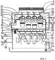
- the oil is sucked out of the oil pan 14 via a suction basket 34 by the oil pump 1 and conveyed into the feed line 20. If the oil pressure is too high, the control valve 33 responds, which is arranged in a branch of the feed line 20 downstream of the oil pump 1 in the direction of the oil pan 14.
- the oil reaches the cylinder cooling chambers 3a to 3d connected in series from the inlet line 20.
- the oil flows out of the cylinder cooling chamber 3d into an outlet line 22 in which a throttle 23 is arranged.
- an inlet line 24 branches off from the outlet line 22 and leads into the series-connected head cooling chambers 4a to 4d.
- the individual head cooling chambers 4a to 4d are each connected via a web bore 21 and a connecting bore 29 to a return line 25 which leads the oil together with the outlet line 22 into an oil thermostat 6.
- Rocker arms 26 arranged in the cylinder head are connected with their bearings 27 to the return line 25.
- the oil thermostat controls a heat exchanger inlet line 7 and a heat exchanger bypass line 8.
- the oil flows through the heat exchanger inlet line 7 to an air-oil heat exchanger 5 and further via a heat exchanger return line 12 to a dirty oil chamber 10 of an oil filter 9. When the oil is cold, the oil passes through the heat exchanger bypass line to the dirty oil room 10.
- the oil After flowing through the oil filter 9, the oil enters the clean oil chamber 11 and from there into the lubrication system 2.
- An outflow line 13 branches off from the heat exchanger bypass line 8 and opens into the oil pan 14.
- a pressure-maintaining valve 15 opening towards the oil pan 14 is arranged in the outflow line 13. This serves to maintain a minimum pressure in the oil system.
- a heating inlet 16 branches off from the outflow line 13 behind the pressure-maintaining valve 15 and leads to a heating heat exchanger (not shown). From there, the oil passes via a heating return 17 and an outlet protection valve 19 opening in the direction of the oil pan back to the outflow line 13 and via the same into the oil pan 14 18. This causes a forced passage through the same when the heating heat exchanger is switched on.
- the pressure holding valve 15 connected in series and the heating pressure valve 18 determine the maximum oil pressure in the oil circuit.
- the leakage protection valve 19 prevents the heating heat exchanger from running dry and thus prevents the oil level in the oil pan 14 from being falsified.
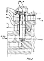
- the view of the oil thermostat 6 shown in FIG. 2 shows the oil thermostat 6 inserted into a housing, which has a thermostat housing 35 and a valve body 36 attached to it.
- the thermostat housing 35 is normally supported by a piston 37 against a wall 38 which is formed by a screw plug 39.
- the oil thermostat is pressed by a spring 40 in the direction of the wall 38.
- the oil coming from the cooling oil circuit through the individual cylinders and the individual cylinder heads passes through the combined drain line 22 and return line 25 into the valve body, flows through it and passes through a control opening 41 into the valve body 36 into the heat exchanger bypass line 8
- a melting ring 42 is arranged, the thermostat housing 35 and the valve body 36, including the control opening 41, are pushed out of their rest position by a certain amount.
- the control opening 41 also releases the heat exchanger inlet line 7, at least in a partial cross section, so that oil can flow into this line even before the internal combustion engine is started up for the first time. This ensures that the specified amount of oil can be filled in when the internal combustion engine is filled for the first time.
- the melting ring 42 melts away with increasing heating of the internal combustion engine or the oil, so that when the oil or the internal combustion engine cools down again, the thermostat housing 35 or the piston 37 comes to rest against the wall 38 and thus in the cold state, the entry of oil into the heat exchanger supply line 7 according to FIG. 3 is prevented.
Landscapes
- Engineering & Computer Science (AREA)
- Mechanical Engineering (AREA)
- General Engineering & Computer Science (AREA)
- Chemical & Material Sciences (AREA)
- Combustion & Propulsion (AREA)
- Physics & Mathematics (AREA)
- Thermal Sciences (AREA)
- Lubrication Of Internal Combustion Engines (AREA)
- Valve Device For Special Equipments (AREA)
- Valve-Gear Or Valve Arrangements (AREA)
Claims (16)
- Moteur à combustion interne avec un carter moteur, qui présente au moins un cylindre recouvert par une tête de cylindre, cylindre dans lequel peut se déplacer un piston articulé au moyen d'une bielle sur un vilebrequin monté dans le carter moteur, le moteur à combustion interne présentant des chambres d'huile de refroidissement réparties dans une chambre de refroidissement des cylindres et dans une chambre de refroidissement de la tête de cylindre, un système de lubrification et une pompe à huile, qui sont reliés pour permettre l'écoulement de l'huile et sont montés en série,
caractérisé en ce que
chaque cylindre présente une chambre séparée de refroidissement de cylindre (3) et chaque tête de cylindre présente une chambre de refroidissement de tête de cylindre (4) séparée, les différentes chambres de refroidissement de cylindre (3a à 3d) et les différentes chambres de refroidissement des têtes de cylindre (4a à 4d) étant montées les unes sous les autres, tandis que les chambres de refroidissement de cylindre (3) ainsi que les chambres de refroidissement de tête de cylindre (4) étant montées comme un tout en série. - Moteur à combustion interne selon la revendication 1,
caractérisé en ce que- la chambre de refroidissement de cylindre (3a) d'un cylindre, situé du côté frontal, est en liaison hydraulique, au moyen d'une conduite d'arrivée (20), avec la pompe à huile (1), et la chambre de refroidissement de cylindre (3d) du cylindre opposé, situé du côté frontal, est en liaison hydraulique avec une conduite de sortie (22) et- dans la conduite de sortie (22), est disposé un étranglement (23) avant lequel part en dérivation une conduite d'alimentation (24) allant aux chambres de refroidissement de tête de cylindre (4) et après lequel une conduite de recyclage (25) débouche des chambres de refroidissement de tête de cylindre (4) dans la conduite de sortie (22). - Moteur à combustion interne selon la revendication 1 ou 2,
caractérisé en ce qu'
une chambre de refroidissement de tête de cylindre (4d), éloignée du volant d'inertie, est en liaison hydraulique au moins par l'intermédiaire d'une ouverture dans un joint de tête de cylindre, avec la chambre de refroidissement de cylindre (3a) situé du côté frontal. - Moteur à combustion interne selon l'une des revendications précédentes,
caractérisé en ce que
chaque chambre individuelle de refroidissement des têtes de cylindre (4a, 4b, 4c, 4d) est en liaison hydraulique avec la conduite de recyclage (25) respectivement au moyen d'un perçage renforcé (21) et d'un perçage de liaison (29) partant de là en dérivation. - Moteur à combustion interne selon l'une des revendications précédentes,
caractérisé en ce que
le sens dans lequel l'écoulement traverse les chambres de refroidissement de tête de cylindre (4) est opposé au sens dans lequel l'écoulement traverse les chambres de refroidissement de cylindre (3) et la conduite de recyclage (25). - Moteur à combustion interne selon l'une des revendications précédentes,
caractérisé en ce que
les paliers (27) des culbuteurs (26) sont en liaison hydraulique avec la conduite de recyclage (25). - Moteur à combustion interne selon l'une des revendications précédentes,
caractérisé en ce qu'
on dispose dans le circuit d'huile, entre les chambres d'huile de refroidissement (3, 4) et le système de lubrification (2), un échangeur de chaleur air-huile (5). - Moteur à combustion interne selon l'une des revendications précédentes,
caractérisé en ce que
dans le circuit d'huile entre les chambres d'huile de refroidissement (3, 4) et l'échangeur de chaleur air-huile (5), on dispose un thermostat (6) qui contrôle une conduite d'admission (7) à l'échangeur de chaleur et une conduite en dérivation (8) par rapport à l'échangeur de chaleur. - Moteur à combustion interne selon l'une des revendications précédentes,
caractérisé en ce que
dans le circuit d'huile, on dispose un filtre à huile (9) avec un espace pour l'huile sale (10) et un espace pour l'huile propre (11), l'espace pour l'huile sale (10) étant en liaison hydraulique avec la conduite de dérivation (8) par rapport à l'échangeur de chaleur et, au moyen d'une conduite de recyclage (12) de l'échangeur de chaleur, avec l'échangeur de chaleur air-huile (5), tandis que l'espace pour l'huile propre (11) est en liaison hydraulique avec le système de lubrification (2). - Moteur à combustion interne selon l'une des revendications précédentes,
caractérisé en ce qu'
on prévoit au moins un injecteur d'huile de piston (28) par cylindre, les injecteurs d'huile de piston (28) étant en liaison hydraulique avec le système de lubrification (2). - Moteur à combustion interne selon l'une des revendications précédentes,
caractérisé en ce qu'
à partir de la conduite de dérivation (8) de l'échangeur de chaleur, part en dérivation dans le sens de l'écoulement, avant le filtre à huile (9), une conduite d'évacuation (13) qui débouche dans un carter d'huile (14)
et en ce que
dans la conduite d'évacuation (13), est disposée une vanne de maintien de pression (15) s'ouvrant en direction du carter d'huile (14). - Moteur à combustion interne selon l'une des revendications précédentes,
caractérisé en ce qu'
à partir de la conduite d'évacuation (13), part en dérivation dans le sens de l'écoulement, derrière la vanne de maintien de pression (15), une arrivée de chauffage (16) et en aval de cette dérivation, débouche un retour de chauffage (17) dans la conduite d'évacuation (13), une vanne de chauffage (18) s'ouvrant en direction du carter d'huile (14) étant disposée dans la conduite d'évacuation (13) entre l'arrivée de chauffage (16) et le retour de chauffage (17), et une vanne de protection de sortie (19) s'ouvrant en direction de la conduite d'évacuation (13), étant disposée dans le circuit de retour de chauffage (17). - Moteur à combustion interne selon l'une des revendications précédentes,
caractérisé en ce que
la somme des pressions d'ouverture de la vanne de maintien de pression (15) et de la vanne de chauffage (18) atteint au moins 3 bars, et la pression d'ouverture de la vanne de protection de sortie (19) atteint à peu près 0,3 bar. - Moteur à combustion interne selon l'une des revendications précédentes,
caractérisé en ce qu'
avant la première mise en service du moteur à combustion interne, on dispose entre le boîtier (35) du thermostat d'huile (6) et une paroi (38) sur laquelle le boîtier de thermostat (35) prend appui au moyen d'un piston (37) qui pousse le boîtier de thermostat à l'encontre de la force d'un ressort (40), un corps susceptible de fondre qui maintient le boîtier de thermostat (35) à distance de la paroi (38). - Moteur à combustion interne selon l'une des revendications précédentes,
caractérisé en ce que
le corps susceptible de fondre est un anneau fusible (42). - Moteur à combustion interne selon l'une des revendications précédentes,
caractérisé en ce que
le corps susceptible de fondre est réalisé en cire.
Applications Claiming Priority (2)
| Application Number | Priority Date | Filing Date | Title |
|---|---|---|---|
| DE4325141A DE4325141A1 (de) | 1993-07-27 | 1993-07-27 | Brennkraftmaschine |
| DE4325141 | 1993-07-27 |
Publications (2)
| Publication Number | Publication Date |
|---|---|
| EP0636772A1 EP0636772A1 (fr) | 1995-02-01 |
| EP0636772B1 true EP0636772B1 (fr) | 1997-08-06 |
Family
ID=6493804
Family Applications (1)
| Application Number | Title | Priority Date | Filing Date |
|---|---|---|---|
| EP94108440A Expired - Lifetime EP0636772B1 (fr) | 1993-07-27 | 1994-06-01 | Moteur à combustion interne |
Country Status (4)
| Country | Link |
|---|---|
| US (1) | US5483928A (fr) |
| EP (1) | EP0636772B1 (fr) |
| AT (1) | ATE156567T1 (fr) |
| DE (2) | DE4325141A1 (fr) |
Families Citing this family (26)
| Publication number | Priority date | Publication date | Assignee | Title |
|---|---|---|---|---|
| US6321699B1 (en) * | 1997-08-25 | 2001-11-27 | Richard Berkeley Britton | Spheroidal rotary valve for combustion engines |
| US6021868A (en) * | 1997-09-02 | 2000-02-08 | Eaton Corporation | Mechanical transmission cooling and lubrication using associated engine systems |
| FR2778204B1 (fr) * | 1998-04-30 | 2000-06-16 | Peugeot | Procede de regulation de la temperature de l'huile de lubrification des organes mecaniques d'un moteur a combustion interne |
| DE19857458A1 (de) * | 1998-12-12 | 2000-06-15 | Deutz Ag | Ölgekühlter Zylinderkopf |
| DE10316340A1 (de) * | 2003-04-10 | 2004-10-28 | Daimlerchrysler Ag | Schmierölkreislauf mit Kolbenkühlung |
| US20050009792A1 (en) * | 2003-07-08 | 2005-01-13 | Deluca Hector F. | (20S)-1alpha-hydroxy-2-methylene-19-nor-vitamin D3 and its uses |
| KR20050032337A (ko) * | 2003-10-01 | 2005-04-07 | 현대자동차주식회사 | 내연기관의 오일 필터 어셈블리 |
| JP4439368B2 (ja) * | 2004-09-29 | 2010-03-24 | 本田技研工業株式会社 | 小型滑走艇用内燃機関 |
| JP4614724B2 (ja) | 2004-09-29 | 2011-01-19 | 本田技研工業株式会社 | 小型滑走艇用内燃機関 |
| JP4297860B2 (ja) * | 2004-09-29 | 2009-07-15 | 本田技研工業株式会社 | 小型滑走艇用内燃機関 |
| JP4573610B2 (ja) * | 2004-09-29 | 2010-11-04 | 本田技研工業株式会社 | 小型滑走艇用内燃機関 |
| DE102005035532A1 (de) * | 2005-07-29 | 2007-02-01 | Dr.Ing.H.C. F. Porsche Ag | Einrichtung für eine Erstbefüllung eines Strömungsmittelkreislaufs |
| DE602005019483D1 (de) * | 2005-11-10 | 2010-04-01 | Renault Trucks | Schmiersystem und solch ein system umfassender verbrennungsmotor |
| DE102006048929A1 (de) * | 2006-10-17 | 2008-04-24 | Deutz Ag | Ölkühlerseitige Schmierölableitung |
| JP2011163146A (ja) * | 2010-02-05 | 2011-08-25 | Ntn Corp | エンジンの潤滑装置 |
| DE102010027816B4 (de) | 2010-04-15 | 2018-09-13 | Ford Global Technologies, Llc | Brennkraftmaschine mit Ölkreislauf und Verfahren zur Erwärmung des Motoröls einer derartigen Brennkraftmaschine |
| DE102010023063B4 (de) * | 2010-06-08 | 2022-05-19 | Dr. Ing. H.C. F. Porsche Aktiengesellschaft | Ölversorgungssystem für eine Brennkraftmaschine |
| CN102275552B (zh) * | 2011-05-24 | 2015-01-14 | 浙江风尚科技有限公司 | 车辆润滑油自动供油系统 |
| US8794210B2 (en) * | 2012-01-05 | 2014-08-05 | Ford Global Technologies, Llc | Engine lubrication system |
| DE102012200746A1 (de) * | 2012-01-19 | 2013-07-25 | Ford Global Technologies, Llc | Brennkraftmaschine mit im Kühlmittelkreislauf angeordneter Pumpe und Verfahren zum Betreiben einer derartigen Brennkraftmaschine |
| US9169801B2 (en) * | 2012-07-31 | 2015-10-27 | Ford Global Technologies, Llc | Internal combustion engine with oil-cooled cylinder block and method for operating an internal combustion engine of said type |
| CN105221231A (zh) * | 2015-11-05 | 2016-01-06 | 重庆驰龙摩托车配件有限公司 | 一种摩托车双缸发动机活塞冷却装置 |
| US20170211715A1 (en) * | 2016-01-21 | 2017-07-27 | GM Global Technology Operations LLC | Oil bypass valve with temporary spacer to provide initially opened fluid circuit |
| JP6792377B2 (ja) * | 2016-08-26 | 2020-11-25 | ダイハツ工業株式会社 | 内燃機関 |
| WO2019129367A1 (fr) * | 2017-12-29 | 2019-07-04 | Volvo Truck Corporation | Circuit de fluide et procédé de commande d'un flux de fluide fourni à au moins un équipement |
| CN113356991B (zh) * | 2020-03-04 | 2022-07-15 | 一汽解放汽车有限公司 | 一种可以检测压力的带过滤功能的活塞冷却系统 |
Family Cites Families (16)
| Publication number | Priority date | Publication date | Assignee | Title |
|---|---|---|---|---|
| SU885577A1 (ru) * | 1961-11-25 | 1981-11-30 | Московский автомеханический институт | Способ охлаждени двигател внутреннего сгорани и устройство дл его осуществлени |
| US3127879A (en) * | 1962-02-10 | 1964-04-07 | Fiat Spa | Cooling cylinder liners of internal combustion engines |
| US3203408A (en) * | 1964-01-06 | 1965-08-31 | Winkelman Henry William | Liquid cooling system for internal combustion engines |
| US3385273A (en) * | 1965-09-10 | 1968-05-28 | White Motor Corp | Cooling system for internal combustion engine |
| IT1048818B (it) * | 1975-11-03 | 1980-12-20 | Brighigna Mario | Motore a combustione interna con raffreddamento a circolazione di un solo liquido |
| US4175503A (en) * | 1976-12-22 | 1979-11-27 | Ford Motor Company | Method of making air engine housing |
| DE2847057A1 (de) * | 1978-10-28 | 1980-05-08 | Daimler Benz Ag | Verbrennungskraftmaschine mit kuehlsystem |
| DE3226880A1 (de) * | 1982-07-17 | 1984-01-19 | Dr.Ing.H.C. F. Porsche Ag, 7000 Stuttgart | Kuehlsystem fuer eine kolben-brennkraftmaschine |
| DE3509095A1 (de) * | 1984-04-11 | 1985-10-17 | Volkswagenwerk Ag, 3180 Wolfsburg | Anordnung zur kuehlung und schmierung einer hubkolben-brennkraftmaschine |
| FR2594885B1 (fr) * | 1986-02-21 | 1988-05-27 | Renault | Circuit de refroidissement pour moteur a combustion interne |
| US4708095A (en) * | 1986-06-16 | 1987-11-24 | Deere & Company | Combined engine cooling and lube system |
| DE3633094A1 (de) * | 1986-09-29 | 1988-03-31 | Kloeckner Humboldt Deutz Ag | Oelkreislaeufe einer brennkraftmaschine |
| DE3633576A1 (de) * | 1986-10-02 | 1988-04-07 | Kloeckner Humboldt Deutz Ag | Brennkraftmaschine |
| DE3638437A1 (de) * | 1986-11-11 | 1988-05-26 | Elsbett L | Kuehl- und schmierkreislauf einer oelgekuehlten brennkraftmaschine |
| YU60389A (sh) * | 1988-04-29 | 1993-10-20 | Steyr-Daimler-Puch Ag. | Uljno hladjeni motor sa unutrašnjim sagorevanjem |
| GB9012364D0 (en) * | 1990-06-02 | 1990-07-25 | Jaguar Cars | Engine cooling systems |
-
1993
- 1993-07-27 DE DE4325141A patent/DE4325141A1/de not_active Withdrawn
-
1994
- 1994-06-01 EP EP94108440A patent/EP0636772B1/fr not_active Expired - Lifetime
- 1994-06-01 DE DE59403620T patent/DE59403620D1/de not_active Expired - Lifetime
- 1994-06-01 AT AT94108440T patent/ATE156567T1/de active
- 1994-07-11 US US08/273,475 patent/US5483928A/en not_active Expired - Lifetime
Also Published As
| Publication number | Publication date |
|---|---|
| US5483928A (en) | 1996-01-16 |
| EP0636772A1 (fr) | 1995-02-01 |
| DE4325141A1 (de) | 1995-02-02 |
| ATE156567T1 (de) | 1997-08-15 |
| DE59403620D1 (de) | 1997-09-11 |
Similar Documents
| Publication | Publication Date | Title |
|---|---|---|
| EP0636772B1 (fr) | Moteur à combustion interne | |
| DE2720034C2 (de) | Schmiersystem | |
| EP0009564B1 (fr) | Cycle de graissage pour moteur à combustion interne | |
| EP1180595B1 (fr) | Système d'alimentation en carburant | |
| DE60208356T2 (de) | Kraftstoffzufuhrsystem | |
| EP0340205B1 (fr) | Moteur à combustion interne refroidi à l'huile | |
| DE19541086A1 (de) | Ventilanordnung für eine Einweg-Kraftstoffanlage | |
| DE2825870A1 (de) | Verbrennungsmotor | |
| DE3151970C2 (de) | Einrichtung zum Steuern des Treibstoffstromes in einem Verbrennungsmotor | |
| DE102017006755A1 (de) | Motorölzuführvorrichtung, Verfahren zum Schützen eines Ölfilters und Computerprogrammprodukt | |
| EP1070836A2 (fr) | Dispositif de refroidissement et / ou de graissage d'un moteur à combustion interne à piston | |
| DE102019218934B4 (de) | Kraftfahrzeug | |
| DE3843827A1 (de) | Brennkraftmaschine mit zwei hydraulischen fluessigkeitskreislaeufen | |
| DE10361189A1 (de) | Kühlsystem für einen Motor | |
| DE10323734B4 (de) | Brennkraftmaschine mit mehreren Zylindern | |
| DE3821302C1 (fr) | ||
| DE4342799C2 (de) | Ölgekühlte Hubkolben-Brennkraftmaschine | |
| DE19900132A1 (de) | Brennkraftmaschine, insbesondere dieselmotorische Viertaktbrennkraftmaschine | |
| DE2511451C3 (de) | Flüssigkeitsgekuhlte Rotationskolben-Brennkraftmaschine | |
| DE3509095A1 (de) | Anordnung zur kuehlung und schmierung einer hubkolben-brennkraftmaschine | |
| DE2830582A1 (de) | Verbrennungskraftmaschine mit einer starthilfeanlage und kraftstoffzufuehreinrichtung als teil einer solchen anlage | |
| DE102006048929A1 (de) | Ölkühlerseitige Schmierölableitung | |
| DE3742315A1 (de) | Schmier- und/oder kuehlmediumbehaelteranordnung, insbesondere fuer eine brennkraftmaschine | |
| DE2832571A1 (de) | Durch eine brennkraftmaschine antreibbares kraftfahrzeug | |
| DE102022104028A1 (de) | Verbrennungsmotor mit interner ölerwärmung von durchblasegas |
Legal Events
| Date | Code | Title | Description |
|---|---|---|---|
| PUAI | Public reference made under article 153(3) epc to a published international application that has entered the european phase |
Free format text: ORIGINAL CODE: 0009012 |
|
| 17P | Request for examination filed |
Effective date: 19941108 |
|
| AK | Designated contracting states |
Kind code of ref document: A1 Designated state(s): AT DE FR GB IT |
|
| 17Q | First examination report despatched |
Effective date: 19960126 |
|
| GRAG | Despatch of communication of intention to grant |
Free format text: ORIGINAL CODE: EPIDOS AGRA |
|
| GRAH | Despatch of communication of intention to grant a patent |
Free format text: ORIGINAL CODE: EPIDOS IGRA |
|
| RAP1 | Party data changed (applicant data changed or rights of an application transferred) |
Owner name: DEUTZ AKTIENGESELLSCHAFT |
|
| RAP1 | Party data changed (applicant data changed or rights of an application transferred) |
Owner name: DEUTZ AKTIENGESELLSCHAFT |
|
| GRAH | Despatch of communication of intention to grant a patent |
Free format text: ORIGINAL CODE: EPIDOS IGRA |
|
| GRAA | (expected) grant |
Free format text: ORIGINAL CODE: 0009210 |
|
| AK | Designated contracting states |
Kind code of ref document: B1 Designated state(s): AT DE FR GB IT |
|
| REF | Corresponds to: |
Ref document number: 156567 Country of ref document: AT Date of ref document: 19970815 Kind code of ref document: T |
|
| ET | Fr: translation filed | ||
| GBT | Gb: translation of ep patent filed (gb section 77(6)(a)/1977) |
Effective date: 19970808 |
|
| REF | Corresponds to: |
Ref document number: 59403620 Country of ref document: DE Date of ref document: 19970911 |
|
| ITF | It: translation for a ep patent filed | ||
| PLBE | No opposition filed within time limit |
Free format text: ORIGINAL CODE: 0009261 |
|
| STAA | Information on the status of an ep patent application or granted ep patent |
Free format text: STATUS: NO OPPOSITION FILED WITHIN TIME LIMIT |
|
| 26N | No opposition filed | ||
| REG | Reference to a national code |
Ref country code: GB Ref legal event code: IF02 |
|
| PGFP | Annual fee paid to national office [announced via postgrant information from national office to epo] |
Ref country code: AT Payment date: 20120613 Year of fee payment: 19 |
|
| PGFP | Annual fee paid to national office [announced via postgrant information from national office to epo] |
Ref country code: GB Payment date: 20130619 Year of fee payment: 20 Ref country code: DE Payment date: 20130626 Year of fee payment: 20 |
|
| PGFP | Annual fee paid to national office [announced via postgrant information from national office to epo] |
Ref country code: IT Payment date: 20130626 Year of fee payment: 20 Ref country code: FR Payment date: 20130703 Year of fee payment: 20 |
|
| REG | Reference to a national code |
Ref country code: DE Ref legal event code: R071 Ref document number: 59403620 Country of ref document: DE |
|
| REG | Reference to a national code |
Ref country code: DE Ref legal event code: R071 Ref document number: 59403620 Country of ref document: DE |
|
| REG | Reference to a national code |
Ref country code: GB Ref legal event code: PE20 Expiry date: 20140531 |
|
| REG | Reference to a national code |
Ref country code: AT Ref legal event code: MK07 Ref document number: 156567 Country of ref document: AT Kind code of ref document: T Effective date: 20140601 |
|
| PG25 | Lapsed in a contracting state [announced via postgrant information from national office to epo] |
Ref country code: GB Free format text: LAPSE BECAUSE OF EXPIRATION OF PROTECTION Effective date: 20140531 |
|
| PG25 | Lapsed in a contracting state [announced via postgrant information from national office to epo] |
Ref country code: DE Free format text: LAPSE BECAUSE OF EXPIRATION OF PROTECTION Effective date: 20140603 |