EP0636833B1 - Apparat zur Trennung von Gas und Flüssigkeit - Google Patents
Apparat zur Trennung von Gas und Flüssigkeit Download PDFInfo
- Publication number
- EP0636833B1 EP0636833B1 EP94111508A EP94111508A EP0636833B1 EP 0636833 B1 EP0636833 B1 EP 0636833B1 EP 94111508 A EP94111508 A EP 94111508A EP 94111508 A EP94111508 A EP 94111508A EP 0636833 B1 EP0636833 B1 EP 0636833B1
- Authority
- EP
- European Patent Office
- Prior art keywords
- liquid
- gas
- separator
- drum
- flow
- Prior art date
- Legal status (The legal status is an assumption and is not a legal conclusion. Google has not performed a legal analysis and makes no representation as to the accuracy of the status listed.)
- Expired - Lifetime
Links
- 239000007788 liquid Substances 0.000 title claims abstract description 102
- 239000000203 mixture Substances 0.000 claims abstract description 17
- 239000012530 fluid Substances 0.000 claims abstract description 16
- 238000007599 discharging Methods 0.000 claims description 8
- 239000002184 metal Substances 0.000 claims description 3
- XLYOFNOQVPJJNP-UHFFFAOYSA-N water Substances O XLYOFNOQVPJJNP-UHFFFAOYSA-N 0.000 abstract description 47
- 239000007791 liquid phase Substances 0.000 abstract description 25
- 238000000926 separation method Methods 0.000 abstract description 17
- 230000003247 decreasing effect Effects 0.000 abstract description 3
- 239000012071 phase Substances 0.000 abstract description 3
- POIUWJQBRNEFGX-XAMSXPGMSA-N cathelicidin Chemical compound C([C@@H](C(=O)N[C@@H](CCCNC(N)=N)C(=O)N[C@@H](CCCCN)C(=O)N[C@@H](CO)C(=O)N[C@@H](CCCCN)C(=O)N[C@@H](CCC(O)=O)C(=O)N[C@@H](CCCCN)C(=O)N[C@@H]([C@@H](C)CC)C(=O)NCC(=O)N[C@@H](CCCCN)C(=O)N[C@@H](CCC(O)=O)C(=O)N[C@@H](CC=1C=CC=CC=1)C(=O)N[C@@H](CCCCN)C(=O)N[C@@H](CCCNC(N)=N)C(=O)N[C@@H]([C@@H](C)CC)C(=O)N[C@@H](C(C)C)C(=O)N[C@@H](CCC(N)=O)C(=O)N[C@@H](CCCNC(N)=N)C(=O)N[C@@H]([C@@H](C)CC)C(=O)N[C@@H](CCCCN)C(=O)N[C@@H](CC(O)=O)C(=O)N[C@@H](CC=1C=CC=CC=1)C(=O)N[C@@H](CC(C)C)C(=O)N[C@@H](CCCNC(N)=N)C(=O)N[C@@H](CC(N)=O)C(=O)N[C@@H](CC(C)C)C(=O)N[C@@H](C(C)C)C(=O)N1[C@@H](CCC1)C(=O)N[C@@H](CCCNC(N)=N)C(=O)N[C@@H]([C@@H](C)O)C(=O)N[C@@H](CCC(O)=O)C(=O)N[C@@H](CO)C(O)=O)NC(=O)[C@H](CC=1C=CC=CC=1)NC(=O)[C@H](CC(O)=O)NC(=O)CNC(=O)[C@H](CC(C)C)NC(=O)[C@@H](N)CC(C)C)C1=CC=CC=C1 POIUWJQBRNEFGX-XAMSXPGMSA-N 0.000 abstract description 2
- 238000010276 construction Methods 0.000 description 4
- 229910000831 Steel Inorganic materials 0.000 description 2
- 239000010959 steel Substances 0.000 description 2
- 230000001133 acceleration Effects 0.000 description 1
- 238000007664 blowing Methods 0.000 description 1
- 230000002349 favourable effect Effects 0.000 description 1
- 230000005484 gravity Effects 0.000 description 1
- 239000003595 mist Substances 0.000 description 1
- 230000002265 prevention Effects 0.000 description 1
Images


Classifications
-
- B—PERFORMING OPERATIONS; TRANSPORTING
- B01—PHYSICAL OR CHEMICAL PROCESSES OR APPARATUS IN GENERAL
- B01D—SEPARATION
- B01D45/00—Separating dispersed particles from gases or vapours by gravity, inertia, or centrifugal forces
- B01D45/12—Separating dispersed particles from gases or vapours by gravity, inertia, or centrifugal forces by centrifugal forces
-
- F—MECHANICAL ENGINEERING; LIGHTING; HEATING; WEAPONS; BLASTING
- F22—STEAM GENERATION
- F22B—METHODS OF STEAM GENERATION; STEAM BOILERS
- F22B37/00—Component parts or details of steam boilers
- F22B37/02—Component parts or details of steam boilers applicable to more than one kind or type of steam boiler
- F22B37/26—Steam-separating arrangements
- F22B37/32—Steam-separating arrangements using centrifugal force
- F22B37/322—Steam-separating arrangements using centrifugal force specially adapted for boiler drums
Definitions
- the present invention relates to a gas-liquid separating apparatus as defined in the preamble of claim 1 and 2, applicable to an electric power plant or the like.
- a steam drum applicable to an electric power plant is shown in Figs. 10 to 13.
- a structure used in this steam drum and shown at 12 in Fig. 10 is called "separator".
- the separator 12 is equipped within a drum 1 as shown in Fig. 10.
- a right half shows an outer appearance of the separator 12, while a left half shows a vertical cross-section view of the separator 12.
- a mist separator 5, a rectifier plate 6 for preventing vortexes, and the like are equipped within the drum 1.
- the separator 12 is composed of a cylinder 9, a cap 11 and a secondary separator 11.
- a structure consisting of a stack of corrugated plates or a structure of fan blade profile is employed.
- gas-liquid mixture fluid 19 fed from a boiler evaporator tube enters a separator inlet 15 through an inlet piping 2.
- a gas component of this gas-liquid mixture fluid is specifically steam, and a liquid component is unevaporated liquid.
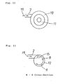
- the gas-liquid mixture fluid 19 fed through the separator inlet 15 enters from the separator inlet 15 into a cylinder 9 in the tangential direction of the cylinder 9 as shown in Fig. 13, thus becomes a rotating flow 8 along the inner wall surface of the cylinder 9, and thereby centrifugal separation between gas and liquid is effected.
- the separated steam is discharged from a secondary separator 11 through a cap 18 to a gas-phase section within a drum 1 as a steam flow 28 shown in Fig. 10. Also, the separated liquid flows out from a primary isolated water outlet 17 to a liquid-phase section within the drum 1 as a primary isolated water 20.
- liquid 7 also partly flows into the secondary separator 11, and as shown in Fig. 10 it flows out as secondary isolated water 13 from a cap gap 16 through a cap bottom 10 to a gas-liquid boundary surface 14 within the drum.
- steam is mixed also in the primary isolated water 20 flowing out from the primary isolated water outlet 17 to the liquid-phase section within the drum.
- the steam in the gas-phase section within the drum 1 is fed from a mist-separator 5 through a steam outlet piping 3 to, for instance, a turbine.
- the liquid in the liquid-phase section is rectified by a rectifier plate 6 provided for the purpose of prevention of vortexes, and thereafter it is returned to, for instance, an inlet of the boiler evaporator tube through a down comer 4.
- the primary isolated water 20 flowing out from the primary isolated water outlet and containing steam flows out from the primary isolated water outlet 17 to a liquid-phase section within the drum 1 as shown in Fig. 10, while retaining a revolving velocity generated by the rotating flow shown at 8 in Fig. 13. Due to this revolving velocity and the gravity acceleration directed vertically downwards, the primary isolated water 20 flowing out from the primary isolated water outlet 17 forms a flow blowing out from the center axis of the separator to the outside while rotating in the same direction as the rotating flow 8.
- the above-described gas-liquid separating apparatus in the prior art had a disadvantage that a time available for gas-liquid gravitational separation of the primary isolated water 20 containing steam in the liquid phase section within the drum 1 is not sufficient and hence it was difficult to achieve gas-liquid separation at a high efficiency as aimed at by the subject apparatus.
- this prior art separating apparatus comprises a container with a liquid surface and a separator disposed within the container for separating gas-liquid mixture fluid incoming thereto into isolated liquid and isolated gas with the aid of centrifugal forces.
- the isolated water portion of the gas-liquid mixture after separation flows down within a shell of the separator in the vertical direction and passes through a perforated plate serving as flow diffuser provided at the bottom of the separator into the water reservoir.
- a perforated plate serving as flow diffuser provided at the bottom of the separator into the water reservoir.
- the water flow passes through vertical anti-vortex plates provided radially above the flow diffuser in the shell.
- This separator thus corresponds essentially to the diffuser of the prior art of Figure 10.
- Another aspect of the present invention is to provide an improved gas-liquid separating apparatus which can practice a highly efficient gas-liquid separating action over a wide range of flow rates.
- a gas-liquid separating apparatus comprising a container having a liquid surface therein, a separator disposed within the container for separating gas-liquid mixture fluid incoming thereto into isolated liquid and isolated gas with the aid of centrifugal forces, said separator being provided with means for discharging said isolated liquid under said liquid surface and said isolated gas above said liquid surface into said container, characterized in that a perforated plate is equipped in a cylindrical shape at an outlet of an isolated liquid flow of said discharging means of said separator.
- a gas-liquid separating apparatus comprising a container having a liquid surface therein and being provided with a downcomer, a separator disposed within the container for separating gas-liquid mixture fluid incoming thereto into isolated liquid and isolated gas with the aid of centrifugal forces, said separator being provided with means for discharging said isolated liquid under said liquid surface and said isolated gas above said liquid surface into said container, and a rectifier means comprising vortex preventing plates and a perforated plate equipped at an outlet of an isolated liquid flow of said discharging means of said separator, characterized in that said perforated plate of said rectifier means has a cylindrical shape and said rectifier means comprises an outflow diverting plate for diverting said discharged isolated liquid in a direction away from the downcomer and through the vortex preventing plates and thereafter through said cylindrical perforated plate.
- a perforated plate generally sold in the market such as a punched metal which has holes of several millimeters to several tens millimeters in diameter punched at a constant pitch, can be employed.
- a perforated plate is equipped at an outlet of an isolated liquid flow of the separator according to the present invention, then among the gas-liquid mixture fluid flowing into the separator, a part of the primary isolated water coming from the rotating flow has its outflow velocity decreased by this perforated plate, and thereafter it flows out to the liquid-phase section within the drum.
- a flow velocity of the primary isolated water flowing out from the outlet of the primary isolated water to the liquid-phase section within the drum is reduced as compared to the case where the prior art was employed, and a flow velocity in the liquid phase section within the drum also becomes slow. Accordingly, a time allowed for gas-liquid gravitational separation in the liquid-phase section within the drum can be reserved longer than that in the heretofore known apparatus.
- the gas-liquid separating apparatus having the construction that rectifier means consisting of an outflow diverting plate, vortex preventing plates and a perforated plate is equipped at an outlet of an isolated liquid flow of the separator according to the present invention
- rectifier means consisting of an outflow diverting plate, vortex preventing plates and a perforated plate
- the primary isolated water coming from the rotating flow has its outflow direction diverted into the direction away from the down comer by the outflow diverting plate after having flowed out from the primary isolated water outlet, subsequently its revolving motion about the center axis of the separator is stopped by the vortex preventing plate, furthermore the outflow velocity to the liquid-phase section within the drum is decelerated by the perforated plate, and simultaneously it becomes primary isolated water flowing out uniformly from the entire perforated plate.
- the gas column within the cylinder can be formed stably owing to the appropriate flow resistances generated by equipping the outflow diverting plate, the vortex preventing plates and the perforated plate, and consequently, gas-liquid separation at a high efficiency can be realized over a wide range of flow rates than that in the case of employing the prior art.
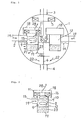
- a perforated plate 23 is used at an outlet of an isolated liquid flow of a separator 12.
- What is called “perforated plate” here could be a perforated plate (punched metal) sold in the market, and for instance, it could be a sheet steel of several millimeters in thickness punched with holes of several millimeters to several tens millimeters in diameter at a constant pitch.
- the perforated plate 23 is formed by working this sheet steel into a cylindrical shape and it is mounted to a separator main body.
- the primary isolated water 21 flowing out through the perforated plate 23 to the liquid-phase section within the drum 1 forms an upward flow in the vicinity of the cylinder 9 as influenced by a buoyancy acting upon a steam component because of a slow outflow velocity. Accordingly, a time available for gas-liquid gravitational separation in the liquid-phase section with the drum 1 can be reserved longer than that in the case of employing the prior art.
- the flow velocity of the primary isolated water 20 flowing out through the primary isolated water outlet 17 to the liquid phase section within the drum 1 can be made smaller than that in the case of employing the prior art owing to the improvement according to the present invention, the amount of the primary isolated water 20 drawn into the flow 22 within the drum can be made smaller than that in the case of employing the prior art, and therefore, the above-described disadvantage of the heretofore known apparatus can be mitigated.
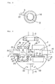
- a rectifier mechanism consisting of an outflow diverting plate 24, vortex preventing plates 25 and a perforated plate 26.
- an outflow diverting plate 24 surrounding a cylinder 9 is equipped.
- the outflow diverting plate 24 consists of a disc-shaped bottom plate and a cylindrical side plate.
- eight vortex preventing plates 25 radially at an equal angular interval as shown in Fig.
- a cylindrical perforated plate 26 is equipped above the top edge of the side plate of the outflow diverting plate 24 as shown in Figs. 5 and 7, and the top of the annular space between this perforated plate 26 and the cylinder 9 is blocked by a top plate 27 as shown in Figs. 5 and 6.
- the primary isolated water 21 flowing out through the perforated plate 26 to the liquid-phase section within the drum 1 becomes an upward flow in the vicinity of the separator 12 as influenced by a buoyancy acting upon a steam component in the primary isolated water 21 because of a slow outflow velocity. Furthermore, since this flow has a slow outflow velocity and a strength of the flow is weak, it cannot become a generation source of a steady flow in the liquid-phase section within the drum 1 as is the case with employment of the prior art.
- gas-liquid separation can be effected more favorably than the apparatus in the prior art.
- rectifier means consisting of an outflow diverting plate, vortex preventing plates and a perforated plate is equipped at an outlet of an isolated liquid flow of a separator according to the present invention
- gas-liquid separation within a drum can be effected more favorably than the case of employing the prior art, and simultaneously, highly efficient gas-liquid separation can be realized in a broader range of flow rates than that in the case of employing the prior art.
Landscapes
- Engineering & Computer Science (AREA)
- General Engineering & Computer Science (AREA)
- Physics & Mathematics (AREA)
- Thermal Sciences (AREA)
- Chemical Kinetics & Catalysis (AREA)
- Mechanical Engineering (AREA)
- Chemical & Material Sciences (AREA)
- Separating Particles In Gases By Inertia (AREA)
- Degasification And Air Bubble Elimination (AREA)
- Separation Using Semi-Permeable Membranes (AREA)
- Cyclones (AREA)
- Vaporization, Distillation, Condensation, Sublimation, And Cold Traps (AREA)
- Gas Separation By Absorption (AREA)
- Treating Waste Gases (AREA)
- Percussion Or Vibration Massage (AREA)
Claims (3)
- Gas/Flüssigkeit-Trennapparat, umfassend:einen Behälter (1) mit einer Flüssigkeitsoberfläche (14) darin,einen im Behälter (1) angeordneten Scheider (12) zum Auftrennen des in ihn eintretenden Gas/Flüssigkeit-Fluid-gemisches (19) in getrennte Flüssigkeit (20, 21) und getrenntes Gas (28) mit Hilfe von Zentrifugalkräften, wobei der Scheider (12) mit Mitteln zum Austragen der getrennten Flüssigkeit (20, 21) unter der Flüssigkeitsoberfläche (14) und des getrennten Gases (28) über der Flüssigkeitsoberfläche (14) in den Behälter (1) versehen ist,dadurch gekennzeichnet, daß eine perforierte Platte (23) in bzw. mit einer zylindrischen Form an einem Auslaß (17) eines getrennten Flüssigkeitsstroms von den Austragmitteln des Scheiders (12) geformt ist.
- Gas/Flüssigkeit-Trennapparat, umfassend:einen Behälter (1), der eine Flüssigkeitsoberfläche (14) darin aufweist und mit einem Abzugsrohr (4) versehen ist,einen im Behälter (1) angeordneten Scheider (12) zum Auftrennen des in ihn eintretenden Gas/Flüssigkeit-Fluidgemisches (19) in getrennte Flüssigkeit (20, 21) und getrenntes Gas (28) mit Hilfe von Zentrifugalkräften, wobei der Scheider (12) mit Mitteln zum Austragen der getrennten Flüssigkeit (20, 21) unter der Flüssigkeitsoberfläche (14) und des getrennten Gases (28) über der Flüssigkeitsoberfläche (14) in den Behälter (1) versehen ist, undeine Rektifiziereinheit mit Wirbelverhinderungs- oder -schutzplatten (25) und einer perforierten Platte (26), die an einem Auslaß (17) eines getrennten Flüssigkeitsstroms von den Austragmitteln des Scheiders (12) angeordnet ist,dadurch gekennzeichnet, daß die perforierte Platte (26) der Rektifiziereinheit eine zylindrische Form aufweist und
die Rektifiziereinheit eine Ausströmablenkplatte (24) zum Ablenken der ausgetragenen getrennten Flüssigkeit in einer Richtung vom Abzugsrohr (4) hinweg und durch die Wirbelschutzplatten (25) und danach durch die zylindrische perforierte Platte (26) umfaßt. - Gas/Flüssigkeit-Trennapparat nach Anspruch 1 oder 2, dadurch gekennzeichnet, daß als perforierte Platte (23; 26) ein gestanztes Metall verwendet wird, in welchem Löcher eines Durchmessers von einigen Millimetern bis zu einem Mehrfachen von 10 mm mit einem konstanten Mittenabstand ausgestanzt sind.
Applications Claiming Priority (2)
| Application Number | Priority Date | Filing Date | Title |
|---|---|---|---|
| JP182662/93 | 1993-07-23 | ||
| JP5182662A JP2786581B2 (ja) | 1993-07-23 | 1993-07-23 | 気液分離装置 |
Publications (2)
| Publication Number | Publication Date |
|---|---|
| EP0636833A1 EP0636833A1 (de) | 1995-02-01 |
| EP0636833B1 true EP0636833B1 (de) | 1997-12-03 |
Family
ID=16122247
Family Applications (1)
| Application Number | Title | Priority Date | Filing Date |
|---|---|---|---|
| EP94111508A Expired - Lifetime EP0636833B1 (de) | 1993-07-23 | 1994-07-22 | Apparat zur Trennung von Gas und Flüssigkeit |
Country Status (7)
| Country | Link |
|---|---|
| US (1) | US5500039A (de) |
| EP (1) | EP0636833B1 (de) |
| JP (1) | JP2786581B2 (de) |
| CN (1) | CN1075182C (de) |
| AT (1) | ATE160853T1 (de) |
| DE (1) | DE69407109T2 (de) |
| FI (1) | FI106886B (de) |
Families Citing this family (47)
| Publication number | Priority date | Publication date | Assignee | Title |
|---|---|---|---|---|
| JPH10221480A (ja) * | 1996-12-06 | 1998-08-21 | Toshiba Corp | 気水分離装置、原子力発電プラント及びボイラー装置 |
| BR9814980A (pt) * | 1997-11-18 | 2000-10-03 | Kvaerner Process Systems As | Separador por gravidade, e, conjunto de entrada para um separador por gravidade. |
| US6843832B2 (en) * | 2001-06-14 | 2005-01-18 | Boyd B. Greene | Compound/curvilinear immiscible liquid separator apparatus and method |
| US6983852B2 (en) * | 2002-10-10 | 2006-01-10 | Specialized Tech Inc. | Desanding apparatus and system |
| US8075668B2 (en) | 2005-03-29 | 2011-12-13 | Dresser-Rand Company | Drainage system for compressor separators |
| JP4796146B2 (ja) * | 2006-08-28 | 2011-10-19 | 三菱重工業株式会社 | 湿分分離器 |
| JP5106812B2 (ja) | 2006-09-05 | 2012-12-26 | 三菱重工コンプレッサ株式会社 | ガスクーラにおけるガス漏れ検知システム |
| CA2664121C (en) * | 2006-09-19 | 2014-05-27 | William C. Maier | Rotary separator drum seal |
| US8302779B2 (en) | 2006-09-21 | 2012-11-06 | Dresser-Rand Company | Separator drum and compressor impeller assembly |
| EP2066983B1 (de) | 2006-09-25 | 2013-12-11 | Dresser-Rand Company | Kompressorbefestigungssystem |
| EP2066453A4 (de) | 2006-09-25 | 2012-04-04 | Dresser Rand Co | Flüssigkeitsdetektor für flüssigkeitstrenngeräte |
| MX2009003177A (es) | 2006-09-25 | 2009-04-03 | Dresser Rand Co | Bobina conectora axialmente movil. |
| EP2066988A4 (de) | 2006-09-25 | 2012-01-04 | Dresser Rand Co | Kopplungsüberwachungssystem |
| MX2009003175A (es) | 2006-09-25 | 2009-04-03 | Dresser Rand Co | Cubierta de acceso para bobina conectora presurizada. |
| MX2009003255A (es) | 2006-09-26 | 2009-04-07 | Dresser Rand Co | Dispositivo separador de fluido estatico mejorado. |
| US8408879B2 (en) | 2008-03-05 | 2013-04-02 | Dresser-Rand Company | Compressor assembly including separator and ejector pump |
| US8062400B2 (en) | 2008-06-25 | 2011-11-22 | Dresser-Rand Company | Dual body drum for rotary separators |
| US8079805B2 (en) | 2008-06-25 | 2011-12-20 | Dresser-Rand Company | Rotary separator and shaft coupler for compressors |
| US7922218B2 (en) | 2008-06-25 | 2011-04-12 | Dresser-Rand Company | Shear ring casing coupler device |
| US8210804B2 (en) | 2009-03-20 | 2012-07-03 | Dresser-Rand Company | Slidable cover for casing access port |
| US8087901B2 (en) | 2009-03-20 | 2012-01-03 | Dresser-Rand Company | Fluid channeling device for back-to-back compressors |
| US8061972B2 (en) | 2009-03-24 | 2011-11-22 | Dresser-Rand Company | High pressure casing access cover |
| EP2478229B1 (de) | 2009-09-15 | 2020-02-26 | Dresser-Rand Company | Kompakte trennvorrichtung auf basis erhöhter dichte |
| EP2482646A4 (de) * | 2009-09-25 | 2017-07-26 | Vivoline Medical AB | Behälter und trägerstruktur zur unterbringung eines organs |
| US20110097216A1 (en) * | 2009-10-22 | 2011-04-28 | Dresser-Rand Company | Lubrication system for subsea compressor |
| BR112012020085B1 (pt) | 2010-02-10 | 2020-12-01 | Dresser-Rand Company | aparelho de coleta para um separador e método de separação |
| RU2434669C1 (ru) * | 2010-06-03 | 2011-11-27 | Пётр Михайлович Трофимов | Центробежный газожидкостный сепаратор |
| WO2012009159A2 (en) | 2010-07-15 | 2012-01-19 | Dresser-Rand Company | Radial vane pack for rotary separators |
| WO2012009158A2 (en) | 2010-07-15 | 2012-01-19 | Dresser-Rand Company | Enhanced in-line rotary separator |
| US8657935B2 (en) | 2010-07-20 | 2014-02-25 | Dresser-Rand Company | Combination of expansion and cooling to enhance separation |
| WO2012012143A2 (en) | 2010-07-21 | 2012-01-26 | Dresser-Rand Company | Multiple modular in-line rotary separator bundle |
| CN102371086A (zh) * | 2010-08-25 | 2012-03-14 | 上海轻工业研究所有限公司 | 气液分离装置 |
| CN101940860B (zh) * | 2010-09-08 | 2012-07-04 | 国家海洋局天津海水淡化与综合利用研究所 | 气液分离机 |
| JP5936144B2 (ja) | 2010-09-09 | 2016-06-15 | ドレッサー ランド カンパニーDresser−Rand Company | 洗浄可能に制御された排水管 |
| US8994237B2 (en) | 2010-12-30 | 2015-03-31 | Dresser-Rand Company | Method for on-line detection of liquid and potential for the occurrence of resistance to ground faults in active magnetic bearing systems |
| EP2659277B8 (de) | 2010-12-30 | 2018-05-23 | Dresser-Rand Company | Verfahren zur online-erkennung von bodenwiderstandsfehlern in aktiven magnetlagersystemen |
| WO2012138545A2 (en) | 2011-04-08 | 2012-10-11 | Dresser-Rand Company | Circulating dielectric oil cooling system for canned bearings and canned electronics |
| WO2012166236A1 (en) | 2011-05-27 | 2012-12-06 | Dresser-Rand Company | Segmented coast-down bearing for magnetic bearing systems |
| US8851756B2 (en) | 2011-06-29 | 2014-10-07 | Dresser-Rand Company | Whirl inhibiting coast-down bearing for magnetic bearing systems |
| US9327214B2 (en) | 2012-02-13 | 2016-05-03 | Specialized Desanders Inc. | Desanding apparatus and a method of using same |
| US9909405B2 (en) | 2012-02-13 | 2018-03-06 | Specialized Desanders Inc. | Desanding apparatus and a method of using same |
| US9938812B2 (en) | 2012-02-13 | 2018-04-10 | Specialized Desanders Inc. | Desanding apparatus and a method of using same |
| CN103657265B (zh) * | 2013-12-10 | 2015-10-21 | 中国海洋石油总公司 | 一种原油伴生气超重力分离装置 |
| CA2836437A1 (en) | 2013-12-16 | 2015-06-16 | Specialized Desanders Inc. | An desanding apparatus and a method of using the same |
| JP6573650B2 (ja) | 2017-09-15 | 2019-09-11 | 住友化学株式会社 | ガス分離方法 |
| CN111219703B (zh) * | 2020-01-20 | 2021-08-13 | 广东韶钢松山股份有限公司 | 锅炉汽包及基于反向模拟分析改造锅炉汽包的方法 |
| CN116440593B (zh) * | 2023-04-14 | 2024-10-22 | 江苏科圣智能装备股份有限公司 | 一种硫酸预转化余热锅炉丝网除沫器 |
Family Cites Families (12)
| Publication number | Priority date | Publication date | Assignee | Title |
|---|---|---|---|---|
| DE896493C (de) * | 1943-11-27 | 1953-11-12 | Alwin Bartl | Fliehkraftabscheider zur Reinigung bzw. Entoelung von Abdampf, Luft, Gasen u. dgl. |
| US2539019A (en) * | 1947-03-27 | 1951-01-23 | Raymond A Hill | Sand separator |
| US2782772A (en) * | 1951-07-06 | 1957-02-26 | Babcock & Wilcox Co | Vapor generator and liquid flow means therefor |
| US3304697A (en) * | 1964-05-21 | 1967-02-21 | Worthington Corp | Oil separator |
| US3488927A (en) * | 1967-10-23 | 1970-01-13 | Shell Oil Co | Gas-liquid cyclone separator |
| DD97289A2 (de) * | 1972-03-17 | 1973-04-23 | ||
| US3928003A (en) * | 1973-06-22 | 1975-12-23 | Procter & Gamble | Vacuum deaerator for viscous liquids |
| US4053291A (en) * | 1976-08-18 | 1977-10-11 | The United States Of America As Represented By The Secretary Of The Air Force | Cylindrical deaerator |
| US4093428A (en) * | 1977-04-12 | 1978-06-06 | The United States Of America As Represented By The Secretary Of The Navy | Gas/liquid separator |
| JPS55119954A (en) * | 1979-03-09 | 1980-09-16 | Toyota Motor Corp | Evaporated-fuel separating apparatus |
| US4483696A (en) * | 1982-09-07 | 1984-11-20 | Foster Wheeler Energy Corporation | Steam separating apparatus and separators used therein |
| JPS61153108A (ja) * | 1984-12-27 | 1986-07-11 | Nishi Nippon Riyuutai Giken:Kk | 流動液体中から気泡を除去する方法および装置ならびにその装置を利用した高流速流力試験用回流水槽 |
-
1993
- 1993-07-23 JP JP5182662A patent/JP2786581B2/ja not_active Expired - Fee Related
-
1994
- 1994-07-13 FI FI943338A patent/FI106886B/fi not_active IP Right Cessation
- 1994-07-22 EP EP94111508A patent/EP0636833B1/de not_active Expired - Lifetime
- 1994-07-22 US US08/277,311 patent/US5500039A/en not_active Expired - Lifetime
- 1994-07-22 CN CN94107998A patent/CN1075182C/zh not_active Expired - Fee Related
- 1994-07-22 AT AT94111508T patent/ATE160853T1/de not_active IP Right Cessation
- 1994-07-22 DE DE69407109T patent/DE69407109T2/de not_active Expired - Fee Related
Also Published As
| Publication number | Publication date |
|---|---|
| FI943338A0 (fi) | 1994-07-13 |
| JP2786581B2 (ja) | 1998-08-13 |
| DE69407109D1 (de) | 1998-01-15 |
| DE69407109T2 (de) | 1998-05-14 |
| JPH0731805A (ja) | 1995-02-03 |
| US5500039A (en) | 1996-03-19 |
| CN1104743A (zh) | 1995-07-05 |
| FI106886B (fi) | 2001-04-30 |
| CN1075182C (zh) | 2001-11-21 |
| FI943338A7 (fi) | 1995-01-24 |
| EP0636833A1 (de) | 1995-02-01 |
| ATE160853T1 (de) | 1997-12-15 |
Similar Documents
| Publication | Publication Date | Title |
|---|---|---|
| EP0636833A1 (de) | Gasflüssigkeit trennender Apparat | |
| US3771290A (en) | Vortex de-aerator | |
| US4148721A (en) | Centrifugal cleaner apparatus and canister type arrangements thereof | |
| US3200568A (en) | Flash separator | |
| EP0046070B1 (de) | Separator | |
| EP0923974B1 (de) | Gas-flüssigkeitsabscheider | |
| CN2335686Y (zh) | 旋流过滤气液分离器 | |
| US3989485A (en) | Process and apparatus for scrubbing exhaust gas from cyclone collectors | |
| RU2103048C1 (ru) | Газожидкостный сепаратор и система разделения жидкости и газа | |
| WO2002100516A2 (en) | A system for separating an entrained liquid component from a gas stream | |
| EP0018840A1 (de) | Vorrichtung zur Abscheidung mitgerissener Feuchtigheit aus gesättigtem Dampf in einem Dampfzeuger einer Kernkraftanlage | |
| US4290791A (en) | Gas-liquid separator | |
| US5520714A (en) | Liquid seal apparatus | |
| US3868236A (en) | Centrifugal gas-liquid separator | |
| US4328013A (en) | Baffle plate for steam separator | |
| US3834127A (en) | Apparatus for the scrubbing of gases | |
| KR100289011B1 (ko) | 원자로 격납용기의 공기로부터 에어러졸을 제거하는 제거장치 | |
| JP2994478B2 (ja) | 竪型熱交換器内を流れるスラッジ含有流体からスラッジを除去する装置 | |
| JP3758838B2 (ja) | 気水分離器 | |
| JPH07232021A (ja) | 気液分離器 | |
| US5236587A (en) | Process and apparatus for the separation of materials from a medium | |
| CN212548665U (zh) | 一种除雾辅助系统、旋流板除雾器及烟囱装置 | |
| JPH0222016Y2 (de) | ||
| SU1261691A1 (ru) | Центробежный рециркул ционный сепаратор | |
| JPS6330486Y2 (de) |
Legal Events
| Date | Code | Title | Description |
|---|---|---|---|
| PUAI | Public reference made under article 153(3) epc to a published international application that has entered the european phase |
Free format text: ORIGINAL CODE: 0009012 |
|
| 17P | Request for examination filed |
Effective date: 19940819 |
|
| AK | Designated contracting states |
Kind code of ref document: A1 Designated state(s): AT BE CH DE FR GB IT LI NL SE |
|
| 17Q | First examination report despatched |
Effective date: 19960410 |
|
| GRAG | Despatch of communication of intention to grant |
Free format text: ORIGINAL CODE: EPIDOS AGRA |
|
| GRAG | Despatch of communication of intention to grant |
Free format text: ORIGINAL CODE: EPIDOS AGRA |
|
| GRAH | Despatch of communication of intention to grant a patent |
Free format text: ORIGINAL CODE: EPIDOS IGRA |
|
| GRAH | Despatch of communication of intention to grant a patent |
Free format text: ORIGINAL CODE: EPIDOS IGRA |
|
| GRAA | (expected) grant |
Free format text: ORIGINAL CODE: 0009210 |
|
| AK | Designated contracting states |
Kind code of ref document: B1 Designated state(s): AT BE CH DE FR GB IT LI NL SE |
|
| REF | Corresponds to: |
Ref document number: 160853 Country of ref document: AT Date of ref document: 19971215 Kind code of ref document: T |
|
| REG | Reference to a national code |
Ref country code: CH Ref legal event code: NV Representative=s name: E. BLUM & CO. PATENTANWAELTE Ref country code: CH Ref legal event code: EP |
|
| ITF | It: translation for a ep patent filed | ||
| REF | Corresponds to: |
Ref document number: 69407109 Country of ref document: DE Date of ref document: 19980115 |
|
| ET | Fr: translation filed | ||
| REG | Reference to a national code |
Ref country code: GB Ref legal event code: 746 Effective date: 19980330 |
|
| PLBE | No opposition filed within time limit |
Free format text: ORIGINAL CODE: 0009261 |
|
| STAA | Information on the status of an ep patent application or granted ep patent |
Free format text: STATUS: NO OPPOSITION FILED WITHIN TIME LIMIT |
|
| REG | Reference to a national code |
Ref country code: FR Ref legal event code: D6 |
|
| 26N | No opposition filed | ||
| REG | Reference to a national code |
Ref country code: GB Ref legal event code: IF02 |
|
| PGFP | Annual fee paid to national office [announced via postgrant information from national office to epo] |
Ref country code: NL Payment date: 20040704 Year of fee payment: 11 |
|
| PGFP | Annual fee paid to national office [announced via postgrant information from national office to epo] |
Ref country code: SE Payment date: 20040706 Year of fee payment: 11 |
|
| PGFP | Annual fee paid to national office [announced via postgrant information from national office to epo] |
Ref country code: FR Payment date: 20040708 Year of fee payment: 11 |
|
| PGFP | Annual fee paid to national office [announced via postgrant information from national office to epo] |
Ref country code: AT Payment date: 20040713 Year of fee payment: 11 |
|
| PGFP | Annual fee paid to national office [announced via postgrant information from national office to epo] |
Ref country code: GB Payment date: 20040721 Year of fee payment: 11 |
|
| PGFP | Annual fee paid to national office [announced via postgrant information from national office to epo] |
Ref country code: DE Payment date: 20040729 Year of fee payment: 11 Ref country code: CH Payment date: 20040729 Year of fee payment: 11 |
|
| PGFP | Annual fee paid to national office [announced via postgrant information from national office to epo] |
Ref country code: BE Payment date: 20040910 Year of fee payment: 11 |
|
| PG25 | Lapsed in a contracting state [announced via postgrant information from national office to epo] |
Ref country code: IT Free format text: LAPSE BECAUSE OF NON-PAYMENT OF DUE FEES;WARNING: LAPSES OF ITALIAN PATENTS WITH EFFECTIVE DATE BEFORE 2007 MAY HAVE OCCURRED AT ANY TIME BEFORE 2007. THE CORRECT EFFECTIVE DATE MAY BE DIFFERENT FROM THE ONE RECORDED. Effective date: 20050722 Ref country code: GB Free format text: LAPSE BECAUSE OF NON-PAYMENT OF DUE FEES Effective date: 20050722 Ref country code: AT Free format text: LAPSE BECAUSE OF NON-PAYMENT OF DUE FEES Effective date: 20050722 |
|
| PG25 | Lapsed in a contracting state [announced via postgrant information from national office to epo] |
Ref country code: SE Free format text: LAPSE BECAUSE OF NON-PAYMENT OF DUE FEES Effective date: 20050723 |
|
| PG25 | Lapsed in a contracting state [announced via postgrant information from national office to epo] |
Ref country code: LI Free format text: LAPSE BECAUSE OF NON-PAYMENT OF DUE FEES Effective date: 20050731 Ref country code: CH Free format text: LAPSE BECAUSE OF NON-PAYMENT OF DUE FEES Effective date: 20050731 Ref country code: BE Free format text: LAPSE BECAUSE OF NON-PAYMENT OF DUE FEES Effective date: 20050731 |
|
| PG25 | Lapsed in a contracting state [announced via postgrant information from national office to epo] |
Ref country code: NL Free format text: LAPSE BECAUSE OF NON-PAYMENT OF DUE FEES Effective date: 20060201 Ref country code: DE Free format text: LAPSE BECAUSE OF NON-PAYMENT OF DUE FEES Effective date: 20060201 |
|
| REG | Reference to a national code |
Ref country code: CH Ref legal event code: PL |
|
| EUG | Se: european patent has lapsed | ||
| GBPC | Gb: european patent ceased through non-payment of renewal fee |
Effective date: 20050722 |
|
| PG25 | Lapsed in a contracting state [announced via postgrant information from national office to epo] |
Ref country code: FR Free format text: LAPSE BECAUSE OF NON-PAYMENT OF DUE FEES Effective date: 20060331 |
|
| NLV4 | Nl: lapsed or anulled due to non-payment of the annual fee |
Effective date: 20060201 |
|
| REG | Reference to a national code |
Ref country code: FR Ref legal event code: ST Effective date: 20060331 |
|
| BERE | Be: lapsed |
Owner name: *MITSUBISHI JUKOGYO K.K. Effective date: 20050731 |