EP0636846A1 - Luftverteilungsvorrichtung für Lebensmittel - Behandlungsräume - Google Patents
Luftverteilungsvorrichtung für Lebensmittel - Behandlungsräume Download PDFInfo
- Publication number
- EP0636846A1 EP0636846A1 EP93830342A EP93830342A EP0636846A1 EP 0636846 A1 EP0636846 A1 EP 0636846A1 EP 93830342 A EP93830342 A EP 93830342A EP 93830342 A EP93830342 A EP 93830342A EP 0636846 A1 EP0636846 A1 EP 0636846A1
- Authority
- EP
- European Patent Office
- Prior art keywords
- air
- manifolds
- flow
- processing
- food products
- Prior art date
- Legal status (The legal status is an assumption and is not a legal conclusion. Google has not performed a legal analysis and makes no representation as to the accuracy of the status listed.)
- Withdrawn
Links
Images
Classifications
-
- F—MECHANICAL ENGINEERING; LIGHTING; HEATING; WEAPONS; BLASTING
- F26—DRYING
- F26B—DRYING SOLID MATERIALS OR OBJECTS BY REMOVING LIQUID THEREFROM
- F26B21/00—Arrangements for supplying or controlling air or other gases for drying solid materials or objects
- F26B21/20—Circulating air or gases in closed cycles, e.g. wholly within the drying enclosure
-
- F—MECHANICAL ENGINEERING; LIGHTING; HEATING; WEAPONS; BLASTING
- F24—HEATING; RANGES; VENTILATING
- F24F—AIR-CONDITIONING; AIR-HUMIDIFICATION; VENTILATION; USE OF AIR CURRENTS FOR SCREENING
- F24F11/00—Control or safety arrangements
- F24F11/30—Control or safety arrangements for purposes related to the operation of the system, e.g. for safety or monitoring
-
- A—HUMAN NECESSITIES
- A23—FOODS OR FOODSTUFFS; TREATMENT THEREOF, NOT COVERED BY OTHER CLASSES
- A23B—PRESERVATION OF FOODS, FOODSTUFFS OR NON-ALCOHOLIC BEVERAGES; CHEMICAL RIPENING OF FRUIT OR VEGETABLES
- A23B4/00—Preservation of meat, sausages, fish or fish products
- A23B4/03—Drying; Subsequent reconstitution
- A23B4/031—Apparatus for drying
-
- F—MECHANICAL ENGINEERING; LIGHTING; HEATING; WEAPONS; BLASTING
- F24—HEATING; RANGES; VENTILATING
- F24F—AIR-CONDITIONING; AIR-HUMIDIFICATION; VENTILATION; USE OF AIR CURRENTS FOR SCREENING
- F24F11/00—Control or safety arrangements
- F24F11/70—Control systems characterised by their outputs; Constructional details thereof
- F24F11/72—Control systems characterised by their outputs; Constructional details thereof for controlling the supply of treated air, e.g. its pressure
- F24F11/74—Control systems characterised by their outputs; Constructional details thereof for controlling the supply of treated air, e.g. its pressure for controlling air flow rate or air velocity
- F24F11/77—Control systems characterised by their outputs; Constructional details thereof for controlling the supply of treated air, e.g. its pressure for controlling air flow rate or air velocity by controlling the speed of ventilators
-
- F—MECHANICAL ENGINEERING; LIGHTING; HEATING; WEAPONS; BLASTING
- F24—HEATING; RANGES; VENTILATING
- F24F—AIR-CONDITIONING; AIR-HUMIDIFICATION; VENTILATION; USE OF AIR CURRENTS FOR SCREENING
- F24F13/00—Details common to, or for air-conditioning, air-humidification, ventilation or use of air currents for screening
- F24F13/26—Arrangements for air-circulation by means of induction, e.g. by fluid coupling or thermal effect
-
- F—MECHANICAL ENGINEERING; LIGHTING; HEATING; WEAPONS; BLASTING
- F24—HEATING; RANGES; VENTILATING
- F24F—AIR-CONDITIONING; AIR-HUMIDIFICATION; VENTILATION; USE OF AIR CURRENTS FOR SCREENING
- F24F2110/00—Control inputs relating to air properties
- F24F2110/20—Humidity
-
- Y—GENERAL TAGGING OF NEW TECHNOLOGICAL DEVELOPMENTS; GENERAL TAGGING OF CROSS-SECTIONAL TECHNOLOGIES SPANNING OVER SEVERAL SECTIONS OF THE IPC; TECHNICAL SUBJECTS COVERED BY FORMER USPC CROSS-REFERENCE ART COLLECTIONS [XRACs] AND DIGESTS
- Y02—TECHNOLOGIES OR APPLICATIONS FOR MITIGATION OR ADAPTATION AGAINST CLIMATE CHANGE
- Y02B—CLIMATE CHANGE MITIGATION TECHNOLOGIES RELATED TO BUILDINGS, e.g. HOUSING, HOUSE APPLIANCES OR RELATED END-USER APPLICATIONS
- Y02B30/00—Energy efficient heating, ventilation or air conditioning [HVAC]
- Y02B30/70—Efficient control or regulation technologies, e.g. for control of refrigerant flow, motor or heating
Definitions
- the present invention relates in general to a system for distributing air in rooms for the processing of food products.
- some examples of use relate to charcuterie-curing cycles using dehumidifying systems, for example, for salami, dry-cured ham and the like, or relate to cooking systems using dry- or moist-air ovens, for example, for mortadella and cooked charcuterie, and possibly also smoked products, or relate to the production of cheeses and the like.
- suitable rooms dehumidified by appropriate conditioners are used for processes such as drying and curing during the commercial production of charcuterie.
- the product is subjected to cycles providing for conditioned air-flows which pass over the charcuterie to remove the moisture therein.
- the charcuterie then needs a period of rest in order to recover, after which the cycle starts again.
- the process takes place in a suitable room which has at least two substantially flat, facing walls, and into which the air is blown vertically in two separate flows which descend along the walls.
- the position of the column relative to the facing walls along which the flows descend is determined by the flow-rates of the two starting flows.
- the ascending column will form in the centre of the room. If one of the two flow-rates is greater than the other, the ascending column will form nearer to the flow with the lesser flow-rate.
- the flow-rates of the two flows are adjusted with the use of shutters or plates in the delivery ducts of the conditioner.
- the technical problem upon which the present invention is based is that of providing an air-distribution system which overcomes the problems mentioned whilst satisfying the requirements mentioned above with reference to the prior art.
- a system for distributing air in rooms for the processing of food products comprising at least one air-delivery pipe, characterized in that the pipe divides into two ducts which direct the air into separate distribution manifolds, fans, driven at variable speeds of rotation, being interposed between the ducts and the manifolds.
- the main advantage of the present invention consists of the fact that the desired flow-rate in the two distribution manifolds can be achieved by suitable regulation of the rates of rotation of the fans.
- the point at which the air coming from the two manifolds will meet can be determined by the presetting of minimum and maximum flow-rate values, and the speed of movement of the flow can be determined by the operation of timing means.
- Another advantage consists of the fact that the behaviour of the whole system is easy to predict at the design stage since there is no variable flow-resistance due to the interference caused by shutters or plates.
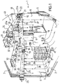
- It has a floor 2, a ceiling 3, two side walls 4, 5 and an end wall 6.
- the side walls 4, 5 and the floor 2 are connected by a concave surface 7.
- the room 1 contains the air-distribution system of the present invention, schematically indicated 40.
- a thermal conditioning unit 8 is disposed in a central position against the end wall 6 for dehumidifying the air by means of conventional cooling and reheating systems.
- the thermal conditioning unit 8 has an upper face 10 from which a delivery pipe 11 and a return pipe 12, both with rectangular cross-sections, extend vertically.
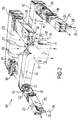
- the delivery pipe 11 divides, at a first "T" junction 13, into two rectangular-sectioned ducts 14, 15 parallel to the end wall 6 and to the ceiling 3.
- each of the ducts 14, 15 has a first right-angle junction 16 which leads to a circular-sectioned pipe 17 or 18.
- Each of the circular-sectioned pipes 17, 18 houses a respective fan, indicated 19 or 20, which, in the embodiment illustrated, is an axial fan comprising a set of blades 21 and a respective electrically-driven motor 22, 22a.
- Another type of fan may, for example, be a centrifugal fan with a motor outside the duct.
- the axes of rotation of the fans 19, 20 coincide with the axes of the circular-sectioned pipes 17, 18 which house them.
- the circular-sectioned pipes 17, 18 are connected, respectively, to distribution manifolds 23, 24 which are shown with rectangular cross-sections in the drawings but may also be of circular cross-section.
- the distribution manifolds 23, 24 comprise lower faces 25 from which a plurality of frustoconical ejectors 26 extends, the ejectors being disposed in vertical positions facing the floor 2.
- the ejectors 26 are aligned in a single row for each face 25 and are spaced apart uniformly.
- the return pipe 12 which is also near the ceiling 3, divides, at a second "T" junction 27, into two ducts 28, 29 with rectangular cross-sections, parallel to the end wall 6 and to the ceiling 3.
- the ducts 28, 29 then have second right-angle junctions 35 from which respective intake manifolds 30, 31 with rectangular cross-sections extend parallel to the ceiling 3 and to the side walls 4, 5.
- the intake manifolds 30, 31 are spaced equally from the side walls 4, 5 and occupy positions intermediate the distribution manifolds 23, 24, so as to be disposed above the floor 2.
- the intake manifolds 30, 31 comprise lower faces 32 which have a plurality of intake openings 33.
- the dehumidified air emitted by the thermal conditioning unit 8 passes through the delivery pipe 11, the first "T” junction 13, the ducts 14, 15, and the first right-angle junction 16, until it comes to the fans 19, 20.
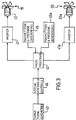
- the speeds of rotation of the fans 19, 20 are regulated by the variation of the frequency and/or the voltage of the electrical energy which supplies the motors 22, 22a, with the use of respective programmed inverters 41, 41a shown in the block diagram of Figure 3.
- the separate variation of the speeds of rotation of the fan 19 and of the fan 20 enables the flow-rate of dehumidified air in the distribution manifolds 23, 24 to be regulated precisely.
- the inverters 41, and 41a are controlled by a microprocessor 42 which receives the air-speed data directly and receives the hygrothermal data relating to the room 1 by means of a general control system 46.
- the hygrothermal data are collected by a probe 43 fixed to a wall of the room and the air-speed data are collected by probes 45, 45a disposed in the two distribution manifolds 23, 24.
- the probes 45, 45a for measuring the air speed are constituted by conventional differential-pressure transmitters.
- the data are sent to the microprocessor 42.
- the microprocessor 42 will then use a suitable programme which can provide the correct speeds of rotation, taking into consideration the type of charcuterie to be produced and the type of curing to be achieved, as well as the data mentioned above.
- the flow-rates of dehumidified air coming from the manifolds 23, 24 give rise to two flows 36, 37 which are output from the frusto-conical ejectors 26 and which flow in contact with the walls 4, 5.
- the flows 36, 37 then encounter the concave surfaces 7 connecting the side walls 4, 5 and the floor 2, which guide the flows 36, 37 in contact with the floor 2.
- the position of the ascending column 34 relative to the walls 4, 5 depends on the flow-rates of the air of the flows 36, 37. If the flow-rate of the flow 36 is greater than the flow-rate of the flow 37, the ascending column 34 will be closer to the wall 5, and vice versa.
- the air flow-rates are varied cyclically, the air will flow over the charcuterie 38 uniformly over the width of the room during the dehumidification period, by virtue of this air-distribution system.
- the presetting of minimum and maximum flow-rate values corresponding to different known speeds of rotation enables the speed of movement of the dehumidified air-flow which passes over the charcuterie 38 to be determined with the use of the timed inverter 41.
Landscapes
- Engineering & Computer Science (AREA)
- Chemical & Material Sciences (AREA)
- Mechanical Engineering (AREA)
- General Engineering & Computer Science (AREA)
- Combustion & Propulsion (AREA)
- Life Sciences & Earth Sciences (AREA)
- Fluid Mechanics (AREA)
- Physics & Mathematics (AREA)
- Wood Science & Technology (AREA)
- Zoology (AREA)
- Food Science & Technology (AREA)
- Polymers & Plastics (AREA)
- Air Conditioning Control Device (AREA)
Priority Applications (1)
| Application Number | Priority Date | Filing Date | Title |
|---|---|---|---|
| EP93830342A EP0636846A1 (de) | 1993-07-30 | 1993-07-30 | Luftverteilungsvorrichtung für Lebensmittel - Behandlungsräume |
Applications Claiming Priority (1)
| Application Number | Priority Date | Filing Date | Title |
|---|---|---|---|
| EP93830342A EP0636846A1 (de) | 1993-07-30 | 1993-07-30 | Luftverteilungsvorrichtung für Lebensmittel - Behandlungsräume |
Publications (1)
| Publication Number | Publication Date |
|---|---|
| EP0636846A1 true EP0636846A1 (de) | 1995-02-01 |
Family
ID=8215211
Family Applications (1)
| Application Number | Title | Priority Date | Filing Date |
|---|---|---|---|
| EP93830342A Withdrawn EP0636846A1 (de) | 1993-07-30 | 1993-07-30 | Luftverteilungsvorrichtung für Lebensmittel - Behandlungsräume |
Country Status (1)
| Country | Link |
|---|---|
| EP (1) | EP0636846A1 (de) |
Cited By (5)
| Publication number | Priority date | Publication date | Assignee | Title |
|---|---|---|---|---|
| EP0827341A3 (de) * | 1996-08-30 | 1999-08-25 | Daiichi Kosho, Co., Ltd. | Karaoke-Wiedergabegerät und -system unter Verwendung von Mehrkanal-Digitalrundfunk |
| FR2787179A1 (fr) | 1998-12-11 | 2000-06-16 | Equip Tech Ind Alimentaires | Procede de thermisation de produits convoyes avec circulation alternee du gaz thermisant |
| FR2836987A1 (fr) * | 2002-03-11 | 2003-09-12 | Priacom | Installation de climatisation |
| WO2014179104A1 (en) * | 2013-04-30 | 2014-11-06 | Eaton Corporation | System and method for controlling output flow of parallel connected blowers |
| IT202300019584A1 (it) * | 2023-09-22 | 2025-03-22 | Frigo Impianti S R L | Cella perfezionata per l'asciugatura di prodotti alimentari. |
Citations (2)
| Publication number | Priority date | Publication date | Assignee | Title |
|---|---|---|---|---|
| US2510524A (en) * | 1947-11-14 | 1950-06-06 | Alex A Schramm | Apparatus for causing variable flow of air in treating rooms |
| EP0449388A1 (de) * | 1990-03-27 | 1991-10-02 | GTI Navep Koudetechniek B.V. | Klimaanlage, insbesondere geeignet zur Behandlung von Fleischprodukten |
-
1993
- 1993-07-30 EP EP93830342A patent/EP0636846A1/de not_active Withdrawn
Patent Citations (2)
| Publication number | Priority date | Publication date | Assignee | Title |
|---|---|---|---|---|
| US2510524A (en) * | 1947-11-14 | 1950-06-06 | Alex A Schramm | Apparatus for causing variable flow of air in treating rooms |
| EP0449388A1 (de) * | 1990-03-27 | 1991-10-02 | GTI Navep Koudetechniek B.V. | Klimaanlage, insbesondere geeignet zur Behandlung von Fleischprodukten |
Cited By (7)
| Publication number | Priority date | Publication date | Assignee | Title |
|---|---|---|---|---|
| EP0827341A3 (de) * | 1996-08-30 | 1999-08-25 | Daiichi Kosho, Co., Ltd. | Karaoke-Wiedergabegerät und -system unter Verwendung von Mehrkanal-Digitalrundfunk |
| FR2787179A1 (fr) | 1998-12-11 | 2000-06-16 | Equip Tech Ind Alimentaires | Procede de thermisation de produits convoyes avec circulation alternee du gaz thermisant |
| FR2836987A1 (fr) * | 2002-03-11 | 2003-09-12 | Priacom | Installation de climatisation |
| WO2003076849A1 (fr) * | 2002-03-11 | 2003-09-18 | Priacom Sarl | Installation de climatisation |
| WO2014179104A1 (en) * | 2013-04-30 | 2014-11-06 | Eaton Corporation | System and method for controlling output flow of parallel connected blowers |
| US9568209B2 (en) | 2013-04-30 | 2017-02-14 | Eaton Corporation | System and method for controlling output flow of parallel connected blowers |
| IT202300019584A1 (it) * | 2023-09-22 | 2025-03-22 | Frigo Impianti S R L | Cella perfezionata per l'asciugatura di prodotti alimentari. |
Similar Documents
| Publication | Publication Date | Title |
|---|---|---|
| EP0399003B1 (de) | Klimaüberwachung für einen individuellen arbeitsplatz | |
| US7766246B2 (en) | Variable speed blower control in an HVAC system having a plurality of zones | |
| US6481635B2 (en) | Environmental control method | |
| US10436457B2 (en) | Variable refrigerant package | |
| US4531454A (en) | Air conditioning system | |
| CN203240682U (zh) | 高洁净与高精度实验室 | |
| AU2014204778B2 (en) | Multi-duct air conditioning system | |
| US6196469B1 (en) | Energy recycling air handling system | |
| CN103335363A (zh) | 一体化集中空气处理系统的控制装置及控制方法 | |
| CN110017541A (zh) | 空调器、运行控制方法和计算机可读存储介质 | |
| US3927827A (en) | Method for controlling the ventilation of an air-conditioning system | |
| CN1268217A (zh) | 加热与冷却用的模块化集成终端及相关的系统 | |
| JP6985794B2 (ja) | 空調システム用の制御装置、空調システム | |
| WO2016204621A2 (en) | Apparatus for blowing air into a space | |
| JPS56117027A (en) | Air conditioning method for dome-shaped building | |
| EP1014011A4 (de) | Verfahren und vorrichtung zur steuerung des luftstromes für eine innenraumeinheit einer klimaanlage | |
| JPS62225842A (ja) | 空気調和機 | |
| US20150267926A1 (en) | Air conditioning system | |
| GB1487745A (en) | Method of or system for air conditioning a plurality of rooms | |
| FI66484C (fi) | Ventilationsfoerfarande och -anlaeggning | |
| JP7766981B2 (ja) | 空調システム | |
| WO2018111710A1 (en) | Variable refrigerant package | |
| FI110280B (fi) | Ilmastointimenetelmä ja ilmastointijärjestelmä | |
| EP4726276A1 (de) | Proaktives hlk-system und verfahren zur proaktiven steuerung des hlk-systems | |
| JP2536234B2 (ja) | 空気調和装置 |
Legal Events
| Date | Code | Title | Description |
|---|---|---|---|
| PUAI | Public reference made under article 153(3) epc to a published international application that has entered the european phase |
Free format text: ORIGINAL CODE: 0009012 |
|
| AK | Designated contracting states |
Kind code of ref document: A1 Designated state(s): AT BE CH DE ES FR IT LI |
|
| RBV | Designated contracting states (corrected) |
Designated state(s): AT BE CH DE ES FR IT LI |
|
| 17P | Request for examination filed |
Effective date: 19950324 |
|
| 17Q | First examination report despatched |
Effective date: 19960507 |
|
| STAA | Information on the status of an ep patent application or granted ep patent |
Free format text: STATUS: THE APPLICATION IS DEEMED TO BE WITHDRAWN |
|
| 18D | Application deemed to be withdrawn |
Effective date: 19961119 |