EP0636847B1 - Four rotatif pour le traitement thermique de matières pouvant s'écouler - Google Patents
Four rotatif pour le traitement thermique de matières pouvant s'écouler Download PDFInfo
- Publication number
- EP0636847B1 EP0636847B1 EP19940109777 EP94109777A EP0636847B1 EP 0636847 B1 EP0636847 B1 EP 0636847B1 EP 19940109777 EP19940109777 EP 19940109777 EP 94109777 A EP94109777 A EP 94109777A EP 0636847 B1 EP0636847 B1 EP 0636847B1
- Authority
- EP
- European Patent Office
- Prior art keywords
- rotary furnace
- outflow
- rotary kiln
- materials
- casing
- Prior art date
- Legal status (The legal status is an assumption and is not a legal conclusion. Google has not performed a legal analysis and makes no representation as to the accuracy of the status listed.)
- Expired - Lifetime
Links
- 239000000463 material Substances 0.000 title claims description 18
- 238000010438 heat treatment Methods 0.000 title claims description 4
- 229910010293 ceramic material Inorganic materials 0.000 claims description 3
- 230000009969 flowable effect Effects 0.000 claims description 3
- 238000005299 abrasion Methods 0.000 claims description 2
- 239000000428 dust Substances 0.000 claims description 2
- 150000001875 compounds Chemical class 0.000 description 5
- 230000035882 stress Effects 0.000 description 4
- 238000004519 manufacturing process Methods 0.000 description 3
- 238000004873 anchoring Methods 0.000 description 2
- 239000011449 brick Substances 0.000 description 2
- 238000010276 construction Methods 0.000 description 2
- 238000001816 cooling Methods 0.000 description 2
- 239000007769 metal material Substances 0.000 description 2
- 239000007787 solid Substances 0.000 description 2
- 125000006850 spacer group Chemical group 0.000 description 2
- 230000008646 thermal stress Effects 0.000 description 2
- 229910001208 Crucible steel Inorganic materials 0.000 description 1
- 229910000831 Steel Inorganic materials 0.000 description 1
- 238000005266 casting Methods 0.000 description 1
- 239000004568 cement Substances 0.000 description 1
- 229910052593 corundum Inorganic materials 0.000 description 1
- 239000010431 corundum Substances 0.000 description 1
- 238000005516 engineering process Methods 0.000 description 1
- 238000002372 labelling Methods 0.000 description 1
- 230000001681 protective effect Effects 0.000 description 1
- 230000005855 radiation Effects 0.000 description 1
- 238000011084 recovery Methods 0.000 description 1
- 238000000926 separation method Methods 0.000 description 1
- 239000010959 steel Substances 0.000 description 1
- 239000000126 substance Substances 0.000 description 1
Images


Classifications
-
- F—MECHANICAL ENGINEERING; LIGHTING; HEATING; WEAPONS; BLASTING
- F27—FURNACES; KILNS; OVENS; RETORTS
- F27B—FURNACES, KILNS, OVENS OR RETORTS IN GENERAL; OPEN SINTERING OR LIKE APPARATUS
- F27B7/00—Rotary-drum furnaces, i.e. horizontal or slightly inclined
- F27B7/20—Details, accessories or equipment specially adapted for rotary-drum furnaces
- F27B7/22—Rotary drums; Supports therefor
- F27B7/224—Discharge ends
Definitions
- the invention relates to a rotary kiln for heat treatment flowable Materials, in particular bulk materials, with a rotary kiln jacket that sends at a distance from the outlet edge of the rotary kiln and that is formed at its outlet end as a double jacket, on the outside at the outlet end of the rotary kiln jacket and cantilevered evenly distributed over the circumference of the rotary kiln jacket Support arms are attached, on which leakage protection segments are arranged, the the completion of this double jacket and the outlet edge of the rotary kiln form.
- FIG Rotary kilns different embodiments of the outlet end of FIG Rotary kilns are known, which has proven particularly useful, the outlet in Form the shape of a double jacket, the end of which is protected by leakage protection segments is completed while the opposite end of this double jacket is open so that cooling air is blown into the cavity of the double jacket can be.
- DE-A-31 46 320 describes a rotary kiln whose outlet end is designed as a double jacket, the front end segments through Fixing screws running in the drum axis direction against the end faces of the double jacket.
- EP-A-0 012 660 a double-walled protective collar that can be cooled from the outside of a rotary kiln outlet end known with an annular two-part Trailing edge, which (divided into a radially inner and radially outer ring) a refractory ramming or casting compound.
- the leak protection segments at the end of the rotary kiln outlet to be carried out in several parts and the individual parts to be stress-free toothed and with the support arms of the rotary kiln shell in the form of detachable
- the leak protection segments at the end of the rotary kiln outlet to be carried out in several parts and the individual parts to be stress-free toothed and with the support arms of the rotary kiln shell in the form of detachable
- the tension-free Connection of the leakage protection segment parts with each other and with the support arms of the rotary kiln jacket the use of particularly heat-resistant and abrasion-resistant Materials for the leak protection segment parts, for example materials such as Corundum or ceramic materials from the Group of hard materials, i.e. materials that normally show brittle behavior and are particularly sensitive to tensile stresses, whereby the Tool life compared to normal metallic materials can be increased significantly can.
- materials such as Corundum or ceramic materials from the Group of hard materials, i.e. materials that normally show brittle behavior and are particularly sensitive to tensile stresses
- the stress-free assembly of the segment parts to leak protection segments also allows the segment parts to be designed according to the expected load to manufacture different materials because of differences in material behavior, e.g. B. the coefficient of thermal expansion, not disadvantageous, for. B. in the form of tension.
- the segment parts are according to the Invention designed so that a high despite the tension-free assembly Mechanical cohesion is largely gas and dust-tight Parting lines.
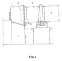
- FIG. 1 schematically shows the furnace outlet area (9) of a rotary kiln (8) shown, with its end edge (20) in the furnace head (7) one of the Rotary kiln (8) downstream cooler (6) protrudes.
- II in Fig. 1 is the Drawn the area of the furnace outlet, which is shown in the following figures is.
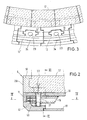
- the furnace outlet area (9) is designed as a double jacket, the inner wall of the rotary kiln jacket (16) and the outer Wall is formed by a tube (18).
- this double jacket is sealed off from leakage protection segments, which are formed from the leakage protection segment parts (11, 11 ', 12, 12') and which extend the rotary kiln (8) by the amount of its length.
- the leakage protection segment parts (11, 11 ', 12, 12') designed and inserted into each other so that only by securing by means of a bolt-shaped body, in the drawing figures this is bolt-shaped Body shown as a screw (21), a non-positive and in their Separation joints largely create dust and gas-tight connections with each other is.
- the leakage protection segment parts are also in the circumferential direction (11, 11 ', 12, 12') arranged in a toothed manner with one another in order to and dustproof joints between the leakage protection segment parts (11, 11 ' or 12, 12 ') to ensure.
- connection of the leak protection segments with the rotary kiln jacket (16) is manufactured via support arms (15).
- the support arms (15) are in this embodiment are designed like a hollow box, so attached (for example welded) that they protrude beyond the end of the rotary kiln jacket (16).
- the leakage protection segments are on this protruding part of the support arms (15) pushed by means of a molded body (19), one end of the molded body (19) in the correspondingly designed recess (23) of the leakage protection segment part (12 or 12 ') and the other end of the shaped body (19) in the cavity of the hollow arm-shaped support arm (15) is inserted.
- the leakage protection segments are locked on the support arms (15) in illustrated embodiment with the aid of a screw (21) from above through the recess (28) in the leak protection segment part (11 or 11 ') and further is guided through the recess (27) of the support arms (15).
- the screw (21) is held by a nut (25), which is designed in a corresponding Groove of the leakage protection segment parts (12 or 12 ') is arranged and on this Way is prevented from rotating when the screw rotates.
- leak protection segment parts (11 or 11 ') On top of the leak protection segment parts (11 or 11 ') are the leak protection segment parts (10) placed flush so that with the leakage protection segment parts (11 or 11 ') a common terminating edge (20) is formed.
- This is kept Leakage protection segment part (10) due to the refractory ramming compound (17) adapts the contours of the vertical part of this leakage protection segment part (10) and by anchors (22) which are welded onto the screws (21) and which by the of the dovetail-shaped horizontal parts of the leak protection segment parts (10) formed recesses with refractory ramming compound (17) filled, protrude.
- FIG. 7 Another, especially for the use of refractory bricks (instead of refractory ramming compound) suitable embodiment of leak protection segments is shown in FIG. 7.
- the abstract the leakage protection segment parts (10 and 11 or 11 ') is one unit required when using refractory bricks, as with refractory ramming compounds possible anchoring, for example anchoring the refractory Masonry using an anchor (22), not possible with stones of this shape or can only be carried out with considerable effort.
- the application examples shown represent the design of the Leakage protection segments with regard to the number and shape of the teeth only possible examples, which according to the invention by other toothing forms can be replaced or supplemented. Also the number of leak protection segment parts, from which the leakage protection segments are formed can be from the number shown in the exemplary embodiments according to the invention differ.
Landscapes
- Engineering & Computer Science (AREA)
- Mechanical Engineering (AREA)
- General Engineering & Computer Science (AREA)
- Muffle Furnaces And Rotary Kilns (AREA)
Claims (3)
- Four tubulaire tournant pour le traitement thermique de matériaux à écoulement libre, en particulier de matériaux en vrac, comprenant une enveloppe de four tubulaire tournant (16) qui se termine avec un intervalle par rapport à l'arête du four tubulaire tournant réalisé à son extrémité, du côté de la sortie, sous la forme d'une double enveloppe à l'extérieur de laquelle, du côté de la sortie du four tubulaire tournant, et sur la périphérie de l'enveloppe (16) du four tubulaire tournant, sont fixés des bras de support (15) en saillie répartis régulièrement, sur lesquels sont disposés des segments de protection de la sortie qui constituent la sortie de cette double enveloppe et l'arête de dégagement du four tubulaire tournant,
caractérisé en ce que
les segments de protection de la sortie du gaz et de la poussière de la double enveloppe sont constitués par des parties de segments de protection de la sortie (11, 11', 12, 12', 13) qui sont poussées les unes dans les autres sous la forme d'une liaison par encliquetage et coopèrent par des dents dans la direction axiale et périphérique de l'enveloppe (16) du four tubulaire tournant et sont reliées sans tension et de manière amovible avec les bras de support (15). - Four tubulaire tournant d'après la revendication 1,
caractérisé en ce que
les parties de segments de protection (10, 11, 11', 12, 12', 13) sont réalisées en matériau céramique résistant à la chaleur et à l'abrasion, en particulier des céramiques du groupe des matériaux à résistance élevée non métalliques. - Four tubulaire tournant d'après une des revendications 1 ou 2,
caractérisé en ce que
des parties de segments de protection de sortie (10, 11, 11', 12, 12', 13) de différents matériaux sont combinées ensemble pour constituer le segment de protection de sortie.
Applications Claiming Priority (2)
| Application Number | Priority Date | Filing Date | Title |
|---|---|---|---|
| DE4325303 | 1993-07-28 | ||
| DE19934325303 DE4325303A1 (de) | 1993-07-28 | 1993-07-28 | Drehrohrofen zur Wärmebehandlung fließfähiger Materialien |
Publications (2)
| Publication Number | Publication Date |
|---|---|
| EP0636847A1 EP0636847A1 (fr) | 1995-02-01 |
| EP0636847B1 true EP0636847B1 (fr) | 1999-03-24 |
Family
ID=6493907
Family Applications (1)
| Application Number | Title | Priority Date | Filing Date |
|---|---|---|---|
| EP19940109777 Expired - Lifetime EP0636847B1 (fr) | 1993-07-28 | 1994-06-24 | Four rotatif pour le traitement thermique de matières pouvant s'écouler |
Country Status (3)
| Country | Link |
|---|---|
| EP (1) | EP0636847B1 (fr) |
| DE (2) | DE4325303A1 (fr) |
| DK (1) | DK0636847T3 (fr) |
Cited By (1)
| Publication number | Priority date | Publication date | Assignee | Title |
|---|---|---|---|---|
| DE102004014872A1 (de) * | 2004-03-26 | 2005-10-13 | Khd Humboldt Wedag Ag | Auslaufende eines Drehrohrofens |
Families Citing this family (3)
| Publication number | Priority date | Publication date | Assignee | Title |
|---|---|---|---|---|
| ES2144330B1 (es) * | 1996-04-24 | 2001-01-01 | Fundiciones Del Estanda S A | Segmentos de salida de horno para plantas cementeras. |
| CN101701765B (zh) * | 2009-09-22 | 2012-12-26 | 洛阳新安电力集团炭素有限公司 | 回转窑窑头护板的改进加固方法 |
| CN113074540B (zh) * | 2020-09-18 | 2023-09-12 | 南京利卡维智能科技有限公司 | 一种多段陶瓷炉管快速拼装结构及材料递进方法 |
Family Cites Families (10)
| Publication number | Priority date | Publication date | Assignee | Title |
|---|---|---|---|---|
| DE900671C (de) * | 1951-01-27 | 1953-12-28 | Miag Vertriebs Gmbh | Gekuehlter Auslauf fuer Drehoefen |
| US3016236A (en) * | 1960-06-22 | 1962-01-09 | Allis Chalmers Mfg Co | Rotary kiln discharge end construction |
| DE1558056B2 (de) * | 1967-02-21 | 1972-12-28 | Klöckner-Humboldt-Deutz AG, 5000 Köln | Befestigungsvorrichtung fuer auslaufschutzsegmente am luftgekuehlten auslaufring fuer drehrohroefen, insbesondere zur zementherstellung |
| DE2160300C3 (de) * | 1971-12-04 | 1975-05-07 | Kloeckner-Humboldt-Deutz Ag, 5000 Koeln | Abstandshalter zwischen den Mänteln eines doppelwandigen, Temperaturdifferenzen ausgesetzten Rohres oder Behälters |
| DE2329061A1 (de) * | 1973-06-07 | 1975-01-02 | Kloeckner Humboldt Deutz Ag | Luftgekuehlter auslaufring fuer einen drehrohrofen |
| DE2852362A1 (de) * | 1977-12-05 | 1979-07-12 | Fives Cail Babcock | Schutzvorrichtung fuer die oeffnung eines drehofens |
| FR2443654A1 (fr) * | 1978-12-07 | 1980-07-04 | Fives Cail Babcock | Dispositif de protection de l'embouchure d'un four rotatif |
| US4212632A (en) * | 1979-05-02 | 1980-07-15 | Allis-Chalmers Corporation | Cooling arrangement for rotary kiln |
| DE3146320A1 (de) * | 1981-11-23 | 1983-08-04 | Krupp Polysius Ag, 4720 Beckum | "drehtrommel fuer heisses gut" |
| SU1408179A1 (ru) * | 1986-07-30 | 1988-07-07 | Карагандинский металлургический комбинат | Разгрузочный конец вращающейс печи |
-
1993
- 1993-07-28 DE DE19934325303 patent/DE4325303A1/de not_active Withdrawn
-
1994
- 1994-06-24 EP EP19940109777 patent/EP0636847B1/fr not_active Expired - Lifetime
- 1994-06-24 DK DK94109777T patent/DK0636847T3/da active
- 1994-06-24 DE DE59407992T patent/DE59407992D1/de not_active Expired - Lifetime
Cited By (1)
| Publication number | Priority date | Publication date | Assignee | Title |
|---|---|---|---|---|
| DE102004014872A1 (de) * | 2004-03-26 | 2005-10-13 | Khd Humboldt Wedag Ag | Auslaufende eines Drehrohrofens |
Also Published As
| Publication number | Publication date |
|---|---|
| DK0636847T3 (da) | 2000-06-05 |
| DE4325303A1 (de) | 1995-02-02 |
| DE59407992D1 (de) | 1999-04-29 |
| EP0636847A1 (fr) | 1995-02-01 |
Similar Documents
| Publication | Publication Date | Title |
|---|---|---|
| EP0895027B1 (fr) | Garniture céramique | |
| DE19502730A1 (de) | Keramische Auskleidung | |
| EP1741981A1 (fr) | Bouclier thermique en céramique et réacteur à gaz hautes températures recouvert d'un tel bouclier | |
| EP0636847B1 (fr) | Four rotatif pour le traitement thermique de matières pouvant s'écouler | |
| DE202012011622U1 (de) | Ausdehnungsverbindung für eine Fluidleitung | |
| DE102008051059A1 (de) | Feuerfestes Auskleidungselement | |
| DE102014215794A1 (de) | Brenner-Lanzen-Einheit | |
| EP2516086B1 (fr) | Fermeture coulissante pour un récipient métallurgique | |
| DE2703064A1 (de) | Kompensator fuer rohr- o.dgl. leitungen, und dessen verwendung | |
| DE2610251C3 (de) | Drehspeicherwärmetauscher | |
| DE900671C (de) | Gekuehlter Auslauf fuer Drehoefen | |
| EP0359916A1 (fr) | Accouplement d'arbres élastique en acier muni d'un revêtement élastomère | |
| DE602004004645T2 (de) | Langgestreckte Stopfenstange | |
| DE604659C (de) | Drehrohrofen | |
| DE2734230C2 (de) | Auslässe eines Drehrohrofens in Satelliten-Kühlerrohre | |
| DE4405382C1 (de) | Brennerrohr für Brenner in Industrieöfen | |
| LU84839A1 (de) | Duesenstock fuer schachtoefen,insbesondere hochoefen | |
| DE4136649C2 (de) | Heißwinddüsenstock für Schachtöfen, insbesondere Hochöfen | |
| EP0673495B1 (fr) | Dispositif d'admission pour l'alimentation de matieres premieres dans un tambour rotatif | |
| DE3639001C1 (en) | Seal of a ceramic pipe | |
| DE2630669A1 (de) | Planetenkuehler fuer drehrohrofen | |
| DE2643412C3 (de) | Drehrohrofen | |
| DE2702876B2 (de) | Drehrohrofen mit einer Anzahl von Planetenkiihlrohren | |
| DE3146320A1 (de) | "drehtrommel fuer heisses gut" | |
| DE1758785C3 (de) | Feuerfeste Ummantelung für Stützglieder von Wärmebehandlungsöfen |
Legal Events
| Date | Code | Title | Description |
|---|---|---|---|
| PUAI | Public reference made under article 153(3) epc to a published international application that has entered the european phase |
Free format text: ORIGINAL CODE: 0009012 |
|
| 17P | Request for examination filed |
Effective date: 19940906 |
|
| AK | Designated contracting states |
Kind code of ref document: A1 Designated state(s): DE DK FR IT |
|
| 17Q | First examination report despatched |
Effective date: 19970219 |
|
| RAP1 | Party data changed (applicant data changed or rights of an application transferred) |
Owner name: DEUTZ AKTIENGESELLSCHAFT |
|
| GRAG | Despatch of communication of intention to grant |
Free format text: ORIGINAL CODE: EPIDOS AGRA |
|
| GRAG | Despatch of communication of intention to grant |
Free format text: ORIGINAL CODE: EPIDOS AGRA |
|
| GRAH | Despatch of communication of intention to grant a patent |
Free format text: ORIGINAL CODE: EPIDOS IGRA |
|
| GRAH | Despatch of communication of intention to grant a patent |
Free format text: ORIGINAL CODE: EPIDOS IGRA |
|
| GRAA | (expected) grant |
Free format text: ORIGINAL CODE: 0009210 |
|
| AK | Designated contracting states |
Kind code of ref document: B1 Designated state(s): DE DK FR IT |
|
| PG25 | Lapsed in a contracting state [announced via postgrant information from national office to epo] |
Ref country code: IT Free format text: LAPSE BECAUSE OF FAILURE TO SUBMIT A TRANSLATION OF THE DESCRIPTION OR TO PAY THE FEE WITHIN THE PRE;WARNING: LAPSES OF ITALIAN PATENTS WITH EFFECTIVE DATE BEFORE 2007 MAY HAVE OCCURRED AT ANY TIME BEFORE 2007. THE CORRECT EFFECTIVE DATE MAY BE DIFFERENT FROM THE ONE RECORDED.SCRIBED TIME-LIMIT Effective date: 19990324 |
|
| REF | Corresponds to: |
Ref document number: 59407992 Country of ref document: DE Date of ref document: 19990429 |
|
| ET | Fr: translation filed | ||
| PLBE | No opposition filed within time limit |
Free format text: ORIGINAL CODE: 0009261 |
|
| STAA | Information on the status of an ep patent application or granted ep patent |
Free format text: STATUS: NO OPPOSITION FILED WITHIN TIME LIMIT |
|
| 26N | No opposition filed | ||
| REG | Reference to a national code |
Ref country code: DK Ref legal event code: T3 |
|
| PGFP | Annual fee paid to national office [announced via postgrant information from national office to epo] |
Ref country code: DK Payment date: 20120620 Year of fee payment: 19 Ref country code: DE Payment date: 20120616 Year of fee payment: 19 |
|
| PGFP | Annual fee paid to national office [announced via postgrant information from national office to epo] |
Ref country code: FR Payment date: 20120705 Year of fee payment: 19 |
|
| REG | Reference to a national code |
Ref country code: DK Ref legal event code: EBP Effective date: 20130630 |
|
| REG | Reference to a national code |
Ref country code: FR Ref legal event code: ST Effective date: 20140228 |
|
| REG | Reference to a national code |
Ref country code: DE Ref legal event code: R119 Ref document number: 59407992 Country of ref document: DE Effective date: 20140101 |
|
| PG25 | Lapsed in a contracting state [announced via postgrant information from national office to epo] |
Ref country code: DE Free format text: LAPSE BECAUSE OF NON-PAYMENT OF DUE FEES Effective date: 20140101 |
|
| PG25 | Lapsed in a contracting state [announced via postgrant information from national office to epo] |
Ref country code: FR Free format text: LAPSE BECAUSE OF NON-PAYMENT OF DUE FEES Effective date: 20130701 |
|
| PG25 | Lapsed in a contracting state [announced via postgrant information from national office to epo] |
Ref country code: DK Free format text: LAPSE BECAUSE OF NON-PAYMENT OF DUE FEES Effective date: 20130630 |