EP0637014A2 - Magnetkopf - Google Patents
Magnetkopf Download PDFInfo
- Publication number
- EP0637014A2 EP0637014A2 EP94111671A EP94111671A EP0637014A2 EP 0637014 A2 EP0637014 A2 EP 0637014A2 EP 94111671 A EP94111671 A EP 94111671A EP 94111671 A EP94111671 A EP 94111671A EP 0637014 A2 EP0637014 A2 EP 0637014A2
- Authority
- EP
- European Patent Office
- Prior art keywords
- magnetic
- gap
- magnetic head
- gap film
- film
- Prior art date
- Legal status (The legal status is an assumption and is not a legal conclusion. Google has not performed a legal analysis and makes no representation as to the accuracy of the status listed.)
- Ceased
Links
Images





Classifications
-
- G—PHYSICS
- G11—INFORMATION STORAGE
- G11B—INFORMATION STORAGE BASED ON RELATIVE MOVEMENT BETWEEN RECORD CARRIER AND TRANSDUCER
- G11B5/00—Recording by magnetisation or demagnetisation of a record carrier; Reproducing by magnetic means; Record carriers therefor
- G11B5/127—Structure or manufacture of heads, e.g. inductive
-
- G—PHYSICS
- G11—INFORMATION STORAGE
- G11B—INFORMATION STORAGE BASED ON RELATIVE MOVEMENT BETWEEN RECORD CARRIER AND TRANSDUCER
- G11B5/00—Recording by magnetisation or demagnetisation of a record carrier; Reproducing by magnetic means; Record carriers therefor
- G11B5/127—Structure or manufacture of heads, e.g. inductive
- G11B5/187—Structure or manufacture of the surface of the head in physical contact with, or immediately adjacent to the recording medium; Pole pieces; Gap features
- G11B5/23—Gap features
- G11B5/235—Selection of material for gap filler
-
- G—PHYSICS
- G11—INFORMATION STORAGE
- G11B—INFORMATION STORAGE BASED ON RELATIVE MOVEMENT BETWEEN RECORD CARRIER AND TRANSDUCER
- G11B5/00—Recording by magnetisation or demagnetisation of a record carrier; Reproducing by magnetic means; Record carriers therefor
- G11B5/127—Structure or manufacture of heads, e.g. inductive
- G11B5/187—Structure or manufacture of the surface of the head in physical contact with, or immediately adjacent to the recording medium; Pole pieces; Gap features
- G11B5/193—Structure or manufacture of the surface of the head in physical contact with, or immediately adjacent to the recording medium; Pole pieces; Gap features the pole pieces being ferrite or other magnetic particles
Definitions
- This invention relates to a magnetic head preferably adapted for being loaded in a recording and/or reproducing apparatus, such as, a video tape recorder (VTR) or a data storage.
- a recording and/or reproducing apparatus such as, a video tape recorder (VTR) or a data storage.
- VTR video tape recorder
- a magnetic head As a magnetic head employed in a 8-mm VTR, a magnetic head, as shown in Fig.1, has been proposed in which a pair of magnetic core substrates 103, 104 having gap films 101, 102 formed thereon by sputtering are abutted to each other on the gap films 101, 102 as abutment surfaces and are bonded to each other to be integrated into one unit by a fused glass 105, with the abutment surfaces forming a magnetic gap functioning as a recording/reproduction gap.
- the magnetic head of such structure employs a soft magnetic oxide material, such as Mn-Zn ferrite or Ni-Zn ferrite for the magnetic core substrates 103, 104.
- the magnetic head employs an oxide non-magnetic material, such as SiO2, for the gap films 101, 102.
- SiO2 is quartz having a coefficient of thermal expansion nearly equal to zero, a residual stress is generated to the ferrite in the heating and cooling processes required for glass fusion. Also, since SiO2 tends to apply a stress to the magnetic core substrates 103, 104 in sputtering formation, the stress lowers magnetic permeability and soft magnetic property of the ferrite portion on which a film of SiO2 is to be formed. As a result, efficiency of the magnetic cores is lowered.
- the structure of SiO2 tends to be rough and chemical potential on the surface rises, causing erosion of SiO2.
- the ferrite is eluted and then precipitates again in the cooling process occur.
- the ferrite may appear to be continuous in optical observation.
- efficiency of the magnetic gap is significantly lowered.
- the elution of the ferrite causes composition deviation of the ferrite itself and hence deterioration of soft magnetism in the vicinity of the magnetic gap, resulting in deterioration of magnetic head performance.
- the low-temperature fusion includes an etching treatment using a sputtering phenomenon, called inverse sputtering, on a gap film formation surface prior to the formation of the gap films on the magnetic core substrates by sputtering.
- the inverse sputtering herein means an etching treatment to the surfaces of the magnetic core substrates by sputtering Ar and N ions to the magnetic core substrates instead of a target of normal sputtering.
- the gap formation surfaces of the magnetic core substrates processed with a predetermined treatment are abraded so that the arithmetical mean deviation of profile Ra prescribed by JIS B0601 is 20 to 100 ⁇ .
- the gap film of SiO2 is formed on the gap formation surface by sputtering.
- the pair of magnetic core substrates are abutted to each other on the gap formation surfaces as abutment surfaces with a gap spacer between them, and are bonded to each other to be integrated into one unit by a fused glass of appropriate composition.
- viscosity of the fused glass in fusion is prescribed.
- the viscosity of the fused glass in fusion may be 160000 (Pa ⁇ s) for sufficiently filling the fused glass into a space between the magnetic core substrates for preventing the erosion of SiO2 due to the fused glass.
- the fusion temperature may be 520°C for obtaining the above-mentioned viscosity in fusion in case where a certain fused glass exhibits viscosity in relation to temperatures as shown in Fig.3.
- the viscosity is expressed by log ⁇ .
- the low-temperature fusion is carried out at 520°C using the glass having the temperature-viscosity characteristics shown in Fig.3.
- a magnetic head having a magnetic gap serving as a recording/reproduction gap between abutment surfaces of magnetic core substrates is formed.
- the erosion of SiO2 at the end of the magnetic gap, the contact of the glass with the ferrite, and the weakening of the leakage magnetic flux from the magnetic gap are less likely to occur than in the previously-described magnetic head, thus improving characteristics.
- the production of the magnetic head using the low-temperature fusion causes the following inconvenience. That is, a deviation in temperature of the fused glass in fusion excessively affects quality of the magnetic head as the end product, and the allowable range of the fusion temperatures is too narrow, thus resulting in unsatisfactory productivity.
- the fused glass is not sufficiently filled in the space between the magnetic core substrates.
- gap films 111, 112 of SiO2 formed on magnetic core substrates 113, 114 are eroded by a fused glass 115, as shown in Fig.4.
- the fused glass reacts with SiO2, forming a reaction layer 116 on the boundary face between the fused glass 115 and the gap films 111, 112, as shown in Fig.5. Thus, it is impossible to perfectly prevent erosion of SiO2.
- a film of SiO2 was formed with a thickness of 850 ⁇ on a substrate formed of magnetic ferrite, and a fused glass having a thickness of 2000 ⁇ estimated to be required for producing the magnetic head with the low-temperature fusion method was formed on the film of SiO2.
- the resulting product was heat-treated at 530°C for one hour.
- the analysis of the boundary face between SiO2 and the magnetic ferrite was conducted with the Auger Electron Spectroscopy. The result is shown in Fig.6. From this result, it can be found that SiO2 reacts with the fused glass, forming the reaction layer on the boundary face, and that erosion of SiO2 is not perfectly prevented.
- abscissas indicate the depth in the direction of film thickness with 0 indicating the surface of the fused glass, while ordinates indicate relative concentration.
- a magnetic head including a pair of magnetic core substrates formed of an oxide magnetic material. At least one of the magnetic core substrates has a gap film formed on an abutment surface thereof. The pair of magnetic core substrates are abutted to each other on the gap film as abutment surfaces thereof, having a magnetic gap between the abutment surfaces.
- the gap film is formed of a material selected from platinum, the platinum group, and an alloy consisting mainly of platinum or the platinum group.
- the pair of magnetic core substrates are bonded to each other to be integrated into one unit by a non-magnetic glass.
- the magnetic gap has a track width of not greater than 50 ⁇ m.
- the gap film has a thickness of not greater than 150 nm.
- the present inventors have found it possible to prevent erosion of the gap film and improve adhesion between the gap film and a fused glass by using a particular material instead of platinum as the gap film.
- a magnetic head including a pair of magnetic core substrates formed of an oxide magnetic material, at least one of the magnetic core substrates having a gap film formed on an abutment surface thereof, the pair of magnetic core substrates being abutted to each other on the gap film as abutment surfaces thereof, having a magnetic gap between the abutment surfaces, the gap film being formed of a material selected from Cr and an alloy consisting mainly of Cr, a material selected from Ti and an alloy consisting mainly of Ti, or a material selected from Ta2O5 and an oxide consisting mainly of Ta2O5.
- the present inventors have found that improving smoothness of a gap film formation surface prior to the formation of the gap film makes it possible to improve characteristics of the magnetic head.
- At least one of the pair of magnetic core substrates has its abutment surface inversely sputtered and then has a gap film formed on the abutment surface.
- Fig.1 is an enlarged plan view showing essential portions of a magnetic recording medium rubbing surface of a conventional magnetic head having a gap film of SiO2.
- Fig.2 is an enlarged plan view showing essential portions of the magnetic recording medium rubbing surface of the conventional magnetic head having the gap film of SiO2, with the gap film being eroded by glass.
- Fig.3 is a diagram showing relations between temperatures and viscosity of a fused glass.
- Fig.4 is an enlarged plan view showing essential portions of the magnetic recording medium rubbing surface of the conventional magnetic head having the gap film of SiO2, in which the gap film and the fused glass of low-temperature fusion are shown.
- Fig.5 is an enlarged plan view showing essential portions of the magnetic recording medium rubbing surface of the conventional magnetic head having the gap film of SiO2, in which the gap film and the fused glass of the optimum-temperature fusion are shown.
- Fig.6 is a graph showing results of the analysis of the boundary face between SiO2 and magnetic ferrite.
- Fig.7 is a perspective view showing an example of a magnetic head according to the present invention.
- Fig.8 is an enlarged plan view showing essential portions of a magnetic recording medium rubbing surface of the magnetic head shown in Fig.7.
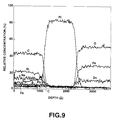
- Fig.9 is a graph showing results of an analysis of a boundary face between platinum and magnetic ferrite.
- Fig.10 is a graph showing track width dependence of the relative output level to an SiO2 gap film with the use of platinum for a gap film.
- Fig.11 is a graph showing gap film thickness dependence of the relative output level to the SiO2 gap film with the use of platinum for the gap film.
- Fig.12 is a perspective view showing a production process of a core half block in a sequence of production processes of the magnetic head of the present invention.
- Fig.13 is a perspective view showing a formation process of a track width restriction groove in the sequence of production processes of the magnetic head of the present invention.
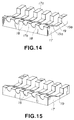
- Fig.14 is a perspective view showing a formation process of a winding groove in the sequence of production processes of the magnetic head of the present invention.
- Fig.15 is a perspective view showing a formation process of a gap film in the sequence of production processes of the magnetic head of the present invention.
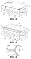
- Fig.16 is a perspective view showing a process of glass fusion in the sequence of production processes of the magnetic head of the present invention.
- Fig.17 is a perspective view showing a formation process of a winding guide groove in the sequence of production processes of the magnetic head of the present invention.
- Fig.18 is an enlarged plan view showing essential portions near the boundary face between the gap film and the fused glass of the magnetic head of the present invention.
- Fig.19 is a graph showing results of an analysis of the boundary face between Cr and the magnetic ferrite.
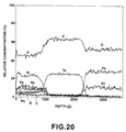
- Fig.20 is a graph showing results of an analysis of the boundary face between Ta2O5 and the magnetic ferrite.
- a magnetic head having a gap film formed of platinum, the platinum group, or an alloy consisting mainly of platinum or the platinum group is described.
- the magnetic head is adapted for being loaded in an 8-mm VTR.
- the magnetic head in the present embodiment has a pair of magnetic core halves 5, 6 including magnetic core substrates 1, 2 of an oxide magnetic material and gap films 3, 4 deposited on abutment surfaces of the magnetic core substrates 1, 2, as shown in Figs.7 and 8.
- the magnetic core halves 5, 6 are abutted to each other on the gap films 3, 4 and are bonded to each other to be integrated into one unit by a fused glass 7.
- a magnetic gap g having an azimuth and serving as a recording/reproduction gap is formed between the abutment surfaces.
- the pair of magnetic core substrates 1, 2 are formed of a soft magnetic oxide material, such as Mn-Zn ferrite or Ni-Zn ferrite.
- Magnetic gap formation surfaces 8, 9 in parallel to the magnetic gap g having the azimuth, and inclined surfaces 10, 11 not in parallel to the magnetic gap formation surfaces 8, 9 and defined by a track with restriction groove, are formed on the abutment surfaces of the magnetic core substrates 1, 2.
- the magnetic gap formation surfaces 8, 9 are formed by notching due to the track width restriction groove, so as to have a track width Tw of the magnetic gap g.
- winding grooves 12, 13 of U-shape cross section for coil winding are passing through in the direction of core thickness.
- Inclined surfaces 12a, 13a of the winding grooves 12, 13, provided on the side of a magnetic recording medium rubbing surface 14, serve to restrict the depth of the magnetic gap g.
- winding guide grooves 15, 16 are provided for assuring the wound state of the coil wound through the winding grooves 12, 13.
- the winding guide grooves 15, 16 are formed in rectangular cross section and in positions opposite to the winding grooves 12, 13.
- the gap films 3, 4 are formed continuously from the front side to the back side on the magnetic gap formation surfaces 8, 9 on the abutment surfaces of the magnetic core substrates 1, 2 and on the inclined surfaces 10, 11 provided on both sides of the gap formation surfaces 8, 9.
- the gap films 3, 4 are also formed in the winding grooves 12, 13. However, it is also permissible not to form the gap films 3, 4 in portions away from the gap formation surfaces 8, 9.
- the pair of magnetic core halves 5, 6 of the above structure are abutted to each other with track positions thereof meeting each other and with a gap spacer provided between the gap films 3, 4 formed on the magnetic gap formation surfaces 8, 9.
- the magnetic core halves 5, 6 are bonded to each other to be integrated into one unit by the non-magnetic fused glass 7 filled in gap portions at both ends of the magnetic gap g.
- the magnetic gap g serving as the recording/reproduction gap is thus formed between the gap films 3, 4.
- the fused glass 7 is filled into the space between the gap films 3, 4 facing each other, and the total thickness of the fused glass 7 and the gap films 3, 4 serves as the gap length, not shown, of the magnetic gap g.
- the track width Tw of the magnetic gap g is not greater than 50 ⁇ m and the thickness of the gap films 3, 4 is not greater than 150 nm, in order to carry out high density magnetic recording.
- platinum, the platinum group, or an alloy consisting mainly of platinum or the platinum group is used for the gap films 3, 4.
- the platinum group is exemplified by ruthenium, rhodium, palladium, osmium and iridium, other than platinum. These platinum and platinum group have characteristics of minute sputtering particles and hence high surface covering property. Since a normal conductive metal has large particles and thus is not suitable for obtaining an image highly magnified in observation of an insulating material with a scanning electron microscope, platinum or a platinum-palladium alloy is employed instead.
- the platinum group has a dense crystalline structure, such as face centered cubic lattice or hexagonal close-packed structure. Therefore, the covering property is improved in comparison with the oxide material, such as SiO2, and the contact of the glass with the ferrite is less likely to occur.
- platinum is used for a pot for producing single crystal of ferrite, platinum has a high melting point and is insoluble into ferrite or glass, thus maintaining the dense film structure without causing erosion or diffusion even in high-temperature fusion due to glass fusion.
- platinum exhibits the coefficient of thermal expansion of 91 ⁇ 10 ⁇ 7 (/°C)
- the Pt-Pd alloy exhibits the coefficient of thermal expansion of approximately 100 ⁇ 10 ⁇ 7 (°C), in conformity with the coefficient of thermal expansion of the ferrite. Therefore, platinum and the Pt-Pd alloy do not generate any residual stress to the ferrite due to sputtering and heat-treatment.
- the magnetic gap is maintained, and the glass, not shown, in the gap and the gap films 3, 4 are maintained in a perfectly non-magnetic state even though the magnetic head is formed with a narrower track width and a shorter gap length. Consequently, a leakage magnetic flux to the magnetic recording medium sufficiently occurs in the magnetic gap, thus achieving high recording/reproduction performance.
- a soft magnetic oxide material such as Mn-Zn ferrite or Ni-Zn ferrite
- plural track width restriction grooves 18 having U-shaped cross section are formed on a major surface 17a of the core half block 17 so that predetermined track widths Tw remain in the longitudinal direction of the block, as shown in Fig.13.
- the U-shaped track width restriction groove 18 is formed, so as to have an angle of the contacting part to the major surface 17a equal to 60°, a groove opening width of 190 ⁇ m, a depth of 95 ⁇ m and a residual track width of 16 ⁇ m.
- the track width restriction groove 18 is formed in the U-shaped cross section in the above example, it may also be formed in a V-shaped cross section.
- a winding groove 19 for winding a coil in the direction orthogonal to the track width restriction groove 18 is formed on the major surface 17a of the core half block 17, as shown in Fig.14.
- the winding groove 19 of cross section having an opening width of 650 ⁇ m, a depth of 200 ⁇ m, an angle of 40° formed by the major surface 17a with an inclined surface 19a in the end portion near the rubbing surface, and an angle 90° formed by the major surface 17a with an inclined surface 19b in the opposite end portion.
- the major surface 17a of the core half block 17 is abraded to have surface roughness of approximately 50 nm.
- a gap film of platinum is formed on the major surface 17a of the core half block 17 including the track width 18 and the winding groove 19, as shown in Fig.15.
- a target of pure platinum having a diameter of 6 inch is sputtered with a making power of 300 W by the RF magnetron sputtering, so as to be 90 nm in film thickness.
- platinum has the coefficient of thermal expansion substantially in conformity of that of ferrite, it does not generate any residual stress to the ferrite due to sputtering.
- a glass stick not shown, is inserted into the winding grooves 19, 19, and is melted through heating so that a fused glass 20 is filled into a space between the track width restriction grooves 18, 18.
- the gap film of platinum is of the dense structure and insoluble into ferrite or glass, even though it is heated at high temperatures in the above fusion process, the gap film is not eroded by the glass and dispersion of ferrite and glass does not occur.
- winding guide grooves 21, 21 are formed in positions opposite to the winding grooves 19 of a core block integrated by the fused glass 20.
- the core block is sliced into chips in the positions indicated by dotted lines in Fig.17 so that the magnetic gap g has an azimuth of 20°.
- a resulting head chip is finished to have an outer dimensional width of 1500 ⁇ m, a height of 1900 ⁇ m and a thickness of 220 ⁇ m.
- Winding was implemented to the magnetic head thus produced so that the inductance was approximately 1.8 ⁇ H, and the output thereof was measured.
- the output of the magnetic head of the same structure except for the gap film of SiO2 was measured.
- the magnetic head having the gap film of platinum exhibited 180 ⁇ Vp-p at 4.5 MHz, while the magnetic head having the gap film of SiO2 exhibited 105 ⁇ Vp-p.
- the gap film of platinum significantly improves the output by approximately 5 dB compared with the gap film of SiO2.
- a magnetic head of the same structure as the magnetic head of Embodiment 1, except for a gap film formed of Cr or an alloy consisting mainly of Cr, will be described.
- the magnetic head of the present embodiment similar to the magnetic head shown in Figs.7 and 8, has the pair of magnetic core halves 5, 6 including the magnetic core substrates 1, 2 of oxide magnetic material and the gap films 3, 4 deposited on the abutment surfaces of the magnetic core substrates 1, 2.
- the magnetic core halves 5, 6 are abutted to each other on the abutment surfaces 3, 4, and are bonded to each other to be integrated into one unit by the fused glass 7.
- the magnetic head g having the azimuth and serving as the recording/reproduction gap is formed between the abutment surfaces. Other parts corresponding to those of Embodiment 1 are not described herein.
- the gap films 3, 4 are formed of Cr or an alloy consisting mainly of Cr.
- Cr and the alloy consisting mainly of Cr are metals, and therefore do not cause particle dispersion due to erosion by glass as in the case of the oxide, such as SiO2.
- the magnetic gap is maintained even though the magnetic head is formed with a narrower track width and a shorter gap length.
- the glass and the gap films 3, 4 in the gap are maintained in the perfectly non-magnetic state. Consequently, the leakage magnetic flux toward the magnetic recording medium sufficiently occurs in the magnetic gap, achieving high recording/reproduction performance.
- an oxidation layer 22 of Cr or an alloy consisting mainly of Cr is formed on the boundary face between the gap films 3, 4 and the fused glass 7, as shown in Fig.18.
- adhesion of the gap films 3, 4 to the fused glass 7 is improved, increasing chip strength of the magnetic head.
- a film of Cr was formed with a thickness of 850 ⁇ on a substrate of ferrite, and a fused glass with a thickness of 2000 ⁇ estimated to be required for producing the magnetic head was formed on the Cr film by sputtering.
- the resulting product was heat-treated at 530°C for one hour.
- the analysis of the boundary face between Cr and the magnetic ferrite at this point was conducted with the Auger Electron Spectroscopy.
- the results of the analysis are shown in Fig.19.
- the results indicate that the oxidation layer is formed on the Cr film surface, and that the magnetic head of the present embodiment having the gap film of Cr or the like exhibits improvement in adhesion of the gap film to the fused glass and an increase in chip strength.
- abscissas indicate the depth in the direction of film thickness with 0 indicating the surface of the fused glass, while ordinates indicate relative concentration.
- a method of producing the magnetic head of the present embodiment will now be described. As the method is substantially equivalent to the production method of Embodiment 1, the corresponding parts will not be described.
- a soft magnetic oxide material such as Mn-Zn ferrite or Ni-Zn ferrite
- the plural track width restriction grooves 18 are formed on the major surface 17a of the core half block 17.
- the track width restriction groove 18 is formed with the one lateral side thereof forming a predetermined angle ⁇ ranging from 8° to 45° with the vertical surface, for example, the other lateral side of the track width restriction groove 18, for preventing crosstalk.
- the track width restriction groove 18 has a depth of approximately 60 ⁇ m and a track width of 15 ⁇ m.
- the major surface 17a of the core half block 17 is abraded to have the arithmetical mean deviation of profile Ra of 20 to 100 ⁇ .
- the winding groove 18 is formed in the direction orthogonal to the track width restriction groove 18.
- a gap film of Cr is formed by sputtering on the major surface 17a of the core half block 17 including the track width restriction groove 18 and the winding groove 19, as shown in Fig.15.
- the gap film of Cr has a thickness of 850 ⁇ .
- a glass stick not shown, is inserted into the winding grooves 19, 19, and is melted by heating so that the fused glass is filled into the space between the track width restriction grooves 18, 18 facing each other.
- the fusion temperature is set in a range of 530 to 560°C, for prescribing the viscosity of the fused glass 20 in fusion.
- the viscosity of 64000 (Pa ⁇ S) for sufficiently filling the fused glass 20 into the space between the core half blocks 17, 17 is obtained at 530°C
- the viscosity of 10000 (Pa ⁇ S) for the glass to start eroding the gap film of Cr in the fusion process is obtained at 560°C.
- the gap film of Cr is metallic and does not cause particle dispersion due to erosion by glass as in the case of an oxide, such as SiO2, even though it is heated at high temperatures in the above fusion process, the gap film is not eroded by the glass and dispersion between ferrite and glass does not occur.
- a head chip produced by various treatments and subsequent slicing into chips as in Embodiment 1 is finished so as to have an outer dimensional width of 1500 ⁇ m and a height of 1900 ⁇ m.
- the azimuth angle is set at 20°.
- the oxidation layer of Cr is formed on the boundary face between the gap film of Cr and the fused glass, adhesion between the gap film and the fused glass is improved and chip strength is increased. Thus, the magnetic head is not damaged in the above-mentioned processes.
- the magnetic head having the gap film of Cr exhibited 170 ⁇ Vp-p at 3.13 m/s, 4.7 MHz, while the magnetic head having the gap film of SiO2 exhibited 112 ⁇ Vp-p.
- the gap film of Cr significantly improves the output by 3.65 dB compared with the gap film of SiO2.
- a magnetic head of the same structure as the magnetic head of Embodiment 2 except for a gap film formed of Ti or an alloy consisting mainly of Ti will be described.
- the magnetic head of the present embodiment has the same structure as the magnetic head of Embodiment 2, except for having gap films of Ti or an alloy consisting mainly of Ti instead of the gap films 3, 4 as shown in Figs.7 and 8.
- Ti and the alloy consisting mainly of Ti are metals, and therefore form a dense film, so that intrusion and displacement by impurity atoms rarely occur. That is, in the magnetic head of the present embodiment, erosion of the gap film and the contact with glass can be avoided, and consequently dispersion between the glass and the ferrite can be eliminated.
- Ti has the coefficient of thermal expansion of 85 ⁇ 10 ⁇ 7 (/°C), which is slightly smaller than that of ferrite, Ti is less likely to generate a residual stress to the ferrite due to sputtering and heat-treatment.
- the oxidation layer 22 of Ti or an alloy consisting mainly of Ti is formed on the boundary face between the gap films 3, 4 and the fused glass 7 as shown in Fig.18.
- adhesion between the gap films 3, 4 and the fused glass 7 is improved, increasing the chip strength of the magnetic head.
- the production method is substantially equivalent to that of Embodiment 2, except for forming a gap film of Ti.
- the gap film of Ti is formed by sputtering on the major surface 17a of the core half block 17 including the track width restriction groove 18 and the winding groove 19, as shown in Fig.15.
- Ti has the coefficient of thermal expansion slightly smaller than that of ferrite, it is less likely to generate a residual stress to the ferrite due to sputtering.
- the core half blocks 17, 17 are superposed with the track positions thereof meeting each other, as shown in Fig.16.
- a glass stick, not shown, is inserted between the winding grooves 19, 19, and is melted by heating to fill the fused glass 20 into a space between the track width restriction grooves 18, 18 facing each other.
- the Ti gap film is of the metal, it does not cause particle dispersion due to erosion by glass as in the oxide, such as SiO2, even though it is heated at high temperatures in the fusion process. Also, since the Ti gap film is of dense structure, erosion of the gap film and contact of glass with ferrite can be avoided, and dispersion between the glass and the ferrite does not occur.
- the winding guide grooves 21, 21 are formed in the core block integrated into one unit by the fused glass 20, as shown in Fig.17.
- a portion to be the rubbing surface to rub the magnetic recording medium is cylindrically abraded to be a curved surface.
- the core block is sliced into chips in positions indicated by dotted lines in Fig.17 so that the azimuth angle of the magnetic gap g is 20°.
- the oxide layer of Ti film is formed on the boundary face between the gap film of Ti and the fused glass, exhibiting high chip strength. Therefore, the magnetic head is not damaged in the above-mentioned various processes.
- the output of the magnetic head of the same structure with the gap film formed of SiO2 was measured.
- the azimuth angle of these magnetic heads was set at 10°.
- the magnetic head having the gap film of Ti exhibited 143 ⁇ Vp-p at 3.13 m/s, 4.7 MHz, while the magnetic head having the gap film of SiO2 exhibited 112 ⁇ Vp-p.
- the Ti gap film significantly improves the output by 2.1 dB compared with the SiO2 gap film.
- a magnetic head having the same structure as the magnetic head of Embodiment 2, except for using a film of Ta2O5 or an oxide consisting mainly of Ta2O5 as the gap film, will be described.
- the magnetic head of the present embodiment has the same structure as the magnetic head described in Embodiment 2, except for using a film of Ta2O5 or an oxide consisting mainly of Ta2O5 as the gap films 3, 4 shown in Figs.7 and 8.
- Ta2O5 or the oxide consisting mainly of Ta2O5 unlike the oxide such as SiO2, causes little dispersion of particles due to erosion by glass.
- erosion of the gap film and contact of the gap film with ferrite can be avoided, thus eliminating dispersion between the glass and the ferrite.
- Ta2O5 has a large coefficient of thermal expansion while SiO2 has a coefficient of thermal expansion nearly equal to zero. Therefore, Ta2O5 applies a smaller stress to the ferrite in sputtering film formation and heat treatment, such as glass fusion, than in case where the SiO2 gap film is formed. Thus, deterioration of magnetic permeability due to the residual stress of the ferrite can be prevented.
- the magnetic gap can be maintained even though the magnetic head is formed with a narrower track width and a shorter gap length.
- the glass in the gap and the gap films 3, 4 are maintained in the perfectly non-magnetic state. Consequently, the leakage magnetic flux toward the magnetic recording medium occurs sufficiently in the magnetic gap part, achieving high recording/reproduction performance.
- the coupling layer 22 of Ta2O5 or the oxide consisting mainly of Ta2O5 is formed on the boundary face between the gap films 3, 4 and the fused glass 7, as shown in Fig.17, similar to the magnetic head of Embodiment 2.
- adhesion between the gap films 3, 4 and the fused glass 7 can be improved, and the chip strength of the magnetic head is increased.
- a film of Ta2O5 was formed with a thickness of 850 ⁇ on a magnetic ferrite substrate, and a fused glass with a thickness of 2000 ⁇ considered to be necessary for producing a magnetic head was formed thereon by sputtering.
- the resulting product was heat-treated at 530°C for one hour.
- the boundary face between Ta2O5 and the magnetic ferrite was analyzed with the Auger Electron Spectroscopy.
- the result of the analysis is shown in Fig.20. From this result, it has been found that oxygen components of the fused glass and Ta2O5 are coupled with each other, improving adhesion between the fused glass and Ta2O5, to increase the chip strength of the magnetic head.
- abscissas indicate the depth in the direction of film thickness with 0 indicating the surface of the fused glass, while ordinates indicate relative concentration.
- Ta2O5 or the oxide consisting mainly of Ta2O5 is used for the gap film, and there is not a great difference between abrasion properties of Ta2O5 or the oxide consisting mainly of Ta2O5 on one hand and the magnetic ferrite forming the magnetic core substrate and the fused glass on the other. Thus, unusual wear is unlikely to occur.
- the present method is substantially equivalent to the method described in Embodiment 2, except for forming the gap film of Ta2O5.
- a gap film of Ta2O5, not shown, is formed by sputtering on the major surface 17a of the core half block 17 including the track width restriction groove 18 and the winding groove 19, as shown in Fig.15. Since Ta2O5 has a coefficient of thermal expansion greater than that of SiO2, Ta2O5 does not cause any residual stress to the ferrite due to sputtering.
- the core half blocks 17, 17 are superposed with the track positions thereof meeting each other, as shown in Fig.16.
- a glass stick, not shown, is inserted into the winding grooves 19, 19, and is melted by heating to fill the fused glass into the space between the facing track width restriction grooves 18, 18.
- the gap film of Ta2O5 is metallic and therefore does not cause particle dispersion due to erosion by glass as in the case of the oxide such as SiO2, even though the Ta2O5 gap film is heated at high temperatures in the fusion process.
- the erosion of the gap film and the contact of the gap film with the glass can be avoided, and the dispersion between the glass and the ferrite does not occur.
- a variety of processing are carried out, as shown in Fig.17.
- the winding guide grooves 21, 21 are formed in the core block integrated into one unit by the fused glass 20, as shown in Fig.17.
- the part to be the rubbing surface to slide on the magnetic recording medium is cylindrically abraded to be a curved surface.
- the core block is sliced into chips in positions indicated by dotted lines in Fig.17 so that the azimuth angle of the magnetic gap g is a predetermined angle.
- oxygen components of the fused glass and the Ta2O5 film are coupled with each other, forming the coupling layer on the boundary face between the gap film of Ta2O5 and the fused glass.
- the adhesion between the gap film and the fused glass is improved, and the chip strength is increased, preventing damages to the magnetic head in the above-mentioned variety of processing.
- the output of a magnetic head of the same structure except for having a gap film of SiO2 was measured.
- the azimuth angle of these magnetic heads were set at 10°.
- the magnetic head having the gap film of Ta2O5 exhibited 143 ⁇ Vp-p at 3.13 m/s, 4.7 MHz, while the magnetic head having the gap film of SiO2 exhibited 112 ⁇ Vp-p.
- the gap film of Ta2O5 greatly improves the output by 2.1 dB compared with the gap film of SiO2.
- platinum, the platinum group, or an alloy consisting mainly of platinum or the platinum group is used for the gap film.
- Platinum, the platinum group, or an alloy consisting mainly of platinum or the platinum group is high in covering property, dense in structure and insoluble into ferrite and glass, and has the coefficient of thermal expansion in conformity with that of ferrite. Therefore, dispersion reaction due to the contact between glass and ferrite can be avoided, and the residual stress can be prevented from being applied to the ferrite. Thus, magnetic permeability and soft magnetic property inherent in ferrite can be sufficiently exhibited.
- the magnetic head of the present invention even though the magnetic head is formed with a narrower track and a narrower gap, information signals can be densely written into the magnetic recording medium and the densely written information signals can be read out. Thus, high density magnetic recording can be achieved.
- the magnetic head of the present invention Cr or an alloy consisting mainly of Cr, which does not cause particle dispersion due to erosion by glass, is used for the gap film. Therefore, dispersion reaction caused by the contact between glass and ferrite can be avoided, and magnetic permeability and soft magnetic property inherent in ferrite can be sufficiently exhibited. Consequently, with the magnetic head of the present invention, even though the magnetic head is formed with a narrower track and a narrower gap, information signals can be densely written into the magnetic recording medium. Thus, high density magnetic recording can be achieved.
- the oxidation layer is formed on the boundary face between the film of Cr or the alloy consisting mainly of Cr and the fused glass, the adhesion between the film and the fused glass is improved and the chip strength can be increased.
- Ti or an alloy consisting mainly of Ti which avoids particle dispersion due to erosion by glass, has dense film structure and has a coefficient of thermal expansion slightly smaller than that of ferrite, is used for the gap film. Therefore, dispersion reaction due to the contact between glass and ferrite can be avoided, and the residual stress can be prevented from being applied to the ferrite. Thus, magnetic permeability and soft magnetic property inherent in ferrite can be sufficiently exhibited. Consequently, with the magnetic head of the present invention, even though the magnetic head is formed with a narrower track and a narrower gap, information signals can be densely written into the magnetic recording medium. Thus, high density magnetic recording can be achieved.
- the oxidation layer is formed on the boundary face between the film of Ti or the alloy consisting mainly of Ti and the fused glass, adhesion between the film and the fused glass can be improved and the chip strength can be increased.
- Ta2O5 or an oxide consisting mainly of Ta2O5 is used for the gap film.
- Ta2O5 or the oxide consisting mainly of Ta2O5 avoids particle dispersion due to erosion by glass, and has dense film structure and a coefficient of thermal expansion slightly smaller than that of ferrite. Therefore, dispersion reaction due to the contact between glass and ferrite can be avoided, and the residual stress can be prevented from being applied to the ferrite. Thus, magnetic permeability and soft magnetic property inherent in ferrite can be sufficiently exhibited. Consequently, with the magnetic head of the present invention, even though the magnetic head is formed with a narrower track and a narrower gap, information signals can be densely written into the magnetic recording medium.
- the magnetic head of the present invention since the oxidation layer is formed on the boundary face between Ta2O5 or the oxide consisting mainly of Ta2O5 and the fused glass, adhesion between the film and the fused glass can be improved and the chip strength can be increased.
- Ta2O5 or the oxide consisting mainly of Ta2O5 having little difference in abrasion property from magnetic ferrite and the fused glass is used for the gap film, unusual wear is unlikely to occur and deterioration in property, such as spacing loss, can be prevented.
Landscapes
- Engineering & Computer Science (AREA)
- Manufacturing & Machinery (AREA)
- Magnetic Heads (AREA)
Applications Claiming Priority (4)
| Application Number | Priority Date | Filing Date | Title |
|---|---|---|---|
| JP18791293 | 1993-07-29 | ||
| JP187912/93 | 1993-07-29 | ||
| JP336252/93 | 1993-12-28 | ||
| JP5336252A JPH0793709A (ja) | 1993-07-29 | 1993-12-28 | 磁気ヘッド |
Publications (2)
| Publication Number | Publication Date |
|---|---|
| EP0637014A2 true EP0637014A2 (de) | 1995-02-01 |
| EP0637014A3 EP0637014A3 (de) | 1996-12-04 |
Family
ID=26504635
Family Applications (1)
| Application Number | Title | Priority Date | Filing Date |
|---|---|---|---|
| EP94111671A Ceased EP0637014A3 (de) | 1993-07-29 | 1994-07-26 | Magnetkopf. |
Country Status (4)
| Country | Link |
|---|---|
| US (1) | US5475551A (de) |
| EP (1) | EP0637014A3 (de) |
| JP (1) | JPH0793709A (de) |
| KR (1) | KR950004107A (de) |
Cited By (1)
| Publication number | Priority date | Publication date | Assignee | Title |
|---|---|---|---|---|
| US5939186A (en) * | 1996-01-29 | 1999-08-17 | Sony Corporation | Magnetic head |
Families Citing this family (2)
| Publication number | Priority date | Publication date | Assignee | Title |
|---|---|---|---|---|
| US5999379A (en) * | 1997-12-11 | 1999-12-07 | International Business Machines Corporation | Spin valve read head with plasma produced metal oxide insulation layer between lead and shield layers and method of making |
| US6198608B1 (en) | 1999-03-18 | 2001-03-06 | Read-Rite Corporation | MR sensor with blunt contiguous junction and slow-milling-rate read gap |
Family Cites Families (11)
| Publication number | Priority date | Publication date | Assignee | Title |
|---|---|---|---|---|
| US3736657A (en) * | 1964-08-18 | 1973-06-05 | P Varadi | Method of manufacturing a transducer head for magnetic recording/reproducing apparatus |
| US3795954A (en) * | 1971-11-26 | 1974-03-12 | Honeywell Inf Systems | Method of making a micro-gap magnetic recording head |
| US4048714A (en) * | 1975-06-12 | 1977-09-20 | Huntt Robert L | Glass bonding of manganese-zinc ferrite |
| JPS6074107A (ja) * | 1983-09-29 | 1985-04-26 | Sony Corp | 磁気ヘツド |
| JPS6350907A (ja) * | 1986-08-19 | 1988-03-03 | Matsushita Electric Ind Co Ltd | 磁気ヘツド |
| US5278716A (en) * | 1987-07-14 | 1994-01-11 | Sanyo Electric Co. | Magnetic head with suppressed generation of pseudogap |
| JP2781849B2 (ja) * | 1987-07-14 | 1998-07-30 | 三洋電機株式会社 | 磁気ヘッド及びその製造方法 |
| JPH0240113A (ja) * | 1988-07-29 | 1990-02-08 | Sharp Corp | 磁気ヘッドの製造方法 |
| JPH0258714A (ja) * | 1988-08-23 | 1990-02-27 | Nippon Mining Co Ltd | 磁気ヘッド |
| EP0378214A1 (de) * | 1989-01-13 | 1990-07-18 | Sanyo Electric Co., Ltd. | Magnetkopf |
| DE69117362T2 (de) * | 1990-07-13 | 1996-07-11 | Fuji Photo Film Co Ltd | Zusammengesetzter Magnetkopf |
-
1993
- 1993-12-28 JP JP5336252A patent/JPH0793709A/ja active Pending
-
1994
- 1994-07-08 US US08/272,324 patent/US5475551A/en not_active Expired - Fee Related
- 1994-07-26 EP EP94111671A patent/EP0637014A3/de not_active Ceased
- 1994-07-28 KR KR1019940018419A patent/KR950004107A/ko not_active Ceased
Cited By (1)
| Publication number | Priority date | Publication date | Assignee | Title |
|---|---|---|---|---|
| US5939186A (en) * | 1996-01-29 | 1999-08-17 | Sony Corporation | Magnetic head |
Also Published As
| Publication number | Publication date |
|---|---|
| EP0637014A3 (de) | 1996-12-04 |
| US5475551A (en) | 1995-12-12 |
| JPH0793709A (ja) | 1995-04-07 |
| KR950004107A (ko) | 1995-02-17 |
Similar Documents
| Publication | Publication Date | Title |
|---|---|---|
| US4819113A (en) | Magnetic transducer head with inclined magnetic gap | |
| EP0299480A2 (de) | Magnetkopf und dessen Herstellungsverfahren | |
| EP0466159B1 (de) | Zusammengesetzter Magnetkopf | |
| US5585984A (en) | Magnetic head | |
| US5475551A (en) | Magnetic head | |
| KR930002393B1 (ko) | 자기헤드 | |
| US5862023A (en) | Metal in gap magnetic head having metal magnetic film including precious metal layer | |
| EP0531514B1 (de) | Magnetkopf zur Aufzeichnung mit hoher Frequenz und hoher Dichte | |
| US5519556A (en) | Magnetic head having separate fusion glass and laminating glass with a track adjustment groove in a magnetic core block | |
| US5708543A (en) | Magnetic head with glass used to bond together two core halves having a coefficient of thermal expansion less than that of the ferromagnetic oxide used to make the core halves | |
| JP2004014108A (ja) | 磁気ヘッドの製造方法 | |
| JP3028109B2 (ja) | 磁気ヘッド | |
| EP0378214A1 (de) | Magnetkopf | |
| JPH07225916A (ja) | 磁気ヘッド | |
| EP0451871B1 (de) | Fliegender zusammengesetzter Magnetkopf | |
| JP3129023B2 (ja) | 磁気ヘッド | |
| KR940011675B1 (ko) | 자기헤드의 제조방법 | |
| JP2550661B2 (ja) | 複合磁気ヘッド | |
| JP3078192B2 (ja) | 磁気ヘッドおよびその製造方法 | |
| JPH07129919A (ja) | 磁気ヘッド | |
| US20020015258A1 (en) | Magnetic head | |
| JPH07296322A (ja) | 磁気ヘッド | |
| JPH0256706A (ja) | 磁気ヘッドコアの製造方法 | |
| JPH0696435A (ja) | 磁気ディスク | |
| JPH09204607A (ja) | 磁気ヘッドの製造方法 |
Legal Events
| Date | Code | Title | Description |
|---|---|---|---|
| PUAI | Public reference made under article 153(3) epc to a published international application that has entered the european phase |
Free format text: ORIGINAL CODE: 0009012 |
|
| AK | Designated contracting states |
Kind code of ref document: A2 Designated state(s): DE FR GB |
|
| PUAL | Search report despatched |
Free format text: ORIGINAL CODE: 0009013 |
|
| AK | Designated contracting states |
Kind code of ref document: A3 Designated state(s): DE FR GB |
|
| 17P | Request for examination filed |
Effective date: 19970505 |
|
| 17Q | First examination report despatched |
Effective date: 19970829 |
|
| STAA | Information on the status of an ep patent application or granted ep patent |
Free format text: STATUS: THE APPLICATION HAS BEEN REFUSED |
|
| 18R | Application refused |
Effective date: 20030327 |