EP0637033B1 - Dynamische Direktzugriffspeicheranordnung mit Spaltenauswahlschaltung mit geringem Leistungsverbrauch - Google Patents
Dynamische Direktzugriffspeicheranordnung mit Spaltenauswahlschaltung mit geringem Leistungsverbrauch Download PDFInfo
- Publication number
- EP0637033B1 EP0637033B1 EP94111639A EP94111639A EP0637033B1 EP 0637033 B1 EP0637033 B1 EP 0637033B1 EP 94111639 A EP94111639 A EP 94111639A EP 94111639 A EP94111639 A EP 94111639A EP 0637033 B1 EP0637033 B1 EP 0637033B1
- Authority
- EP
- European Patent Office
- Prior art keywords
- data
- coupled
- data lines
- memory device
- sections
- Prior art date
- Legal status (The legal status is an assumption and is not a legal conclusion. Google has not performed a legal analysis and makes no representation as to the accuracy of the status listed.)
- Expired - Lifetime
Links
Images


Classifications
-
- G—PHYSICS
- G11—INFORMATION STORAGE
- G11C—STATIC STORES
- G11C11/00—Digital stores characterised by the use of particular electric or magnetic storage elements; Storage elements therefor
- G11C11/21—Digital stores characterised by the use of particular electric or magnetic storage elements; Storage elements therefor using electric elements
- G11C11/34—Digital stores characterised by the use of particular electric or magnetic storage elements; Storage elements therefor using electric elements using semiconductor devices
- G11C11/40—Digital stores characterised by the use of particular electric or magnetic storage elements; Storage elements therefor using electric elements using semiconductor devices using transistors
- G11C11/401—Digital stores characterised by the use of particular electric or magnetic storage elements; Storage elements therefor using electric elements using semiconductor devices using transistors forming cells needing refreshing or charge regeneration, i.e. dynamic cells
- G11C11/4063—Auxiliary circuits, e.g. for addressing, decoding, driving, writing, sensing or timing
- G11C11/407—Auxiliary circuits, e.g. for addressing, decoding, driving, writing, sensing or timing for memory cells of the field-effect type
- G11C11/409—Read-write [R-W] circuits
- G11C11/4096—Input/output [I/O] data management or control circuits, e.g. reading or writing circuits, I/O drivers or bit-line switches
-
- G—PHYSICS
- G11—INFORMATION STORAGE
- G11C—STATIC STORES
- G11C11/00—Digital stores characterised by the use of particular electric or magnetic storage elements; Storage elements therefor
- G11C11/21—Digital stores characterised by the use of particular electric or magnetic storage elements; Storage elements therefor using electric elements
- G11C11/34—Digital stores characterised by the use of particular electric or magnetic storage elements; Storage elements therefor using electric elements using semiconductor devices
- G11C11/40—Digital stores characterised by the use of particular electric or magnetic storage elements; Storage elements therefor using electric elements using semiconductor devices using transistors
- G11C11/401—Digital stores characterised by the use of particular electric or magnetic storage elements; Storage elements therefor using electric elements using semiconductor devices using transistors forming cells needing refreshing or charge regeneration, i.e. dynamic cells
- G11C11/4063—Auxiliary circuits, e.g. for addressing, decoding, driving, writing, sensing or timing
- G11C11/407—Auxiliary circuits, e.g. for addressing, decoding, driving, writing, sensing or timing for memory cells of the field-effect type
- G11C11/409—Read-write [R-W] circuits
- G11C11/4093—Input/output [I/O] data interface arrangements, e.g. data buffers
-
- G—PHYSICS
- G11—INFORMATION STORAGE
- G11C—STATIC STORES
- G11C7/00—Arrangements for writing information into, or reading information out from, a digital store
- G11C7/10—Input/output [I/O] data interface arrangements, e.g. I/O data control circuits, I/O data buffers
- G11C7/1048—Data bus control circuits, e.g. precharging, presetting, equalising
Definitions
- This invention relates to a dynamic random access memory device and, more particularly, to a dynamic random access memory device having a low-power consumption column selector for transferring a potential difference on a selected bit line pair to a data line pair.
- FIG. 1 A typical example of the dynamic random access memory device is illustrated in figure 1 of the drawings, and the prior art dynamic random access memory device largely comprises a first memory cell array 1, a second memory cell array 2, an array of sense amplifier circuits SA1 to SAn shared between the first and second memory cell arrays 1 and 2, a first transfer gate array 3 associated with the first memory cell array 1, a second transfer gate array 4 associated with the second memory cell array 2, a column selector 5 for selectively coupling the sense amplifier circuits SA1 to SAn through a data line pair DL to a data amplifier circuit 6 and a charging circuit 7 for the data line pair DL.
- the prior art dynamic random access memory device further comprises a write-in circuit etc., figure 1 does not show these circuits, because they are less important for understanding problems inherent in the prior art dynamic random access memory device.
- the first memory cell array 1 is implemented by a plurality of memory cells for storing data bits in the form of potential difference, and the memory cells are indicated by small circles.
- a plurality of bit line pairs BLa1, BLa2,... and BLan are selectively coupled with the input/output nodes of the memory cells, and word lines WLa are further selectively coupled to the control nodes of the memory cells.
- the word lines WLa are selectively driven to an active level, and the stored data bits are transferred from the associated memory cells to the bit line pairs BLa1 to BLan.
- the second memory cell array 2 is also arranged. Namely, a plurality of memory cells form a matrix, and are selectively coupled to a plurality of word lines WLb1/ WLb2 and a plurality of digit line pairs BLb1, BLb2,... and BLbn. If one of the word lines such as WLb1 is energized, the associated memory cells delivers the stored data bits to the bit line pairs, respectively.
- the first transfer gate array 3 has a plurality of sets of n-channel enhancement type transfer transistors Qn1/Qn2 coupled between the bit line pairs BLa1 to BLan and the sense amplifier circuits SA1 to SAn, and a first transfer signal TG1 causes the n-channel enhancement type transfer transistors Qn1/Qn2 to concurrently turn on for coupling the sense amplifier circuits SA1 to SAn to the digit line pairs BLa1 to BLan.
- a plurality of sets of n-channel enhancement type transfer transistors Qn3/Qn4 form the second transfer gate array 4, and a second transfer signal TG2 concurrently changes the n-channel enhancement type transfer transistors Qn3/Qn4 between on-state and off-state so as to couple the sense amplifier circuits SA1 to SAn to the digit line pairs BLb1 to BLbn.
- the sense amplifier circuits SA1 to SAn are operative to rapidly develop potential differences at the input/output nodes thereof, and the arrangement of each sense amplifier is well know to a person skilled in the art.
- the column selector unit 5 comprises a plurality of switching circuits 51 to 5n respectively associated with the sense amplifier circuits SA1 to SAn, and each of the switching circuits 51 to 5n has a first parallel combination of n-channel enhancement type switching transistors Qn5/Qn6 coupled to the data line pair DL and a second parallel combination of n-channel enhancement type switching transistors Qn7/Qn8 coupled between the first parallel combination and a discharging line DSC.
- Column address decoded signals Y1 to Yn are distributed to the switching circuits 51 to 5n, and the n-channel enhancement type switching transistors Qn5/Qn6 are gated by one of the column address decoded signals Y1 to Yn.
- the gate electrodes of the n-channel enhancement type switching transistors Qn7 and Qn8 are coupled to the pair of input/output nodes of the associated sense amplifier circuit SA1, SA2,... or SAn. If the column address decoded signals Y1 to Yn enable the switching circuit 51, the n-channel enhancement type switching transistors Qn5 and Qn6 turn on, and the input/output nodes of the sense amplifier circuit SA1 causes the n-channel enhancement type switching transistors Qn7/Qn8 to selectively turn on and off. As a result, one of the data lines of the pair DL is coupled through the switching circuit 51 to the discharging line DSC, and the potential difference between the input and output nodes of the sense amplifier circuit SA1 is relayed to the data line pair DL.
- the charging circuit 7 is implemented by a parallel combination of p-channel enhancement type charging transistors Qp9 and Qp10, and the p-channel enhancement type charging transistors Qp9 and Qp10 are coupled between a power voltage line Vcc and the data lines of the pair DL.
- the gate electrodes of the p-channel enhancement type charging transistors Qp9 and Qp10 are coupled to the drain nodes, and are maintained in the on-state at all times. For this reason, the data lines are charged to a predetermined level lower than the power voltage level Vcc by the threshold of the p-channel enhancement type charging transistors Qp9 and Qp10 before the column address decoded signals Y1 to Yn select one of the switching circuits 51 to 5n.
- bit line pairs BLa1 to DLan and DLb1 to BLbn have been already charged to a precharge level.
- description is hereinbelow focused on the second memory cell array 2.
- the row address bits are decoded, and the word line WLb1 is changed to the active level.
- the memory cells coupled to the word line WLb1 deliver the data bits to the associated bit line pairs BLb1 to BLbn, respectively, and produce potential differences on the associated bit line pairs BLb1 to BLbn, respectively.
- the transfer signal TG2 is changed to the active high voltage level, and the other transfer signal TG1 remains low.
- the n-channel enhancement type transfer transistors Qn3 and Qn4 turn on, and the n-channel enhancement type transfer transistors Qn1 and Qn2 are maintained in the off-state.
- the potential differences on the bit line pairs BLb1 to BLbn are propagated to the sense amplifier circuits SA1 to SAn, respectively.
- the sense amplifier circuits SA1 to SAn are activated so as to rapidly develop the potential differences.
- the n-channel enhancement type transfer transistors Qn3 and Qn4 are assumed to propagate a high voltage level and a low voltage level, respectively.
- the column address decoded signal Y1 allows the n-channel enhancement type switching transistors Qn5/Qn6 of the switching circuit 51 to turn on, and the other column address decoded signals keep the other n-channel enhancement type switching transistors Qn5/Qn6 of the other switching circuits 52 to 5n off. For this reason, the switching circuit 51 becomes responsive to the potential difference supplied from the sense amplifier circuit SA1.
- the potential difference indicative of the data bit read out from the memory cell MCx allows the n-channel enhancement type switching transistor Qn7 to produce a conductive channel from the data line to the discharging line DSC and the other n-channel enhancement type switching transistor Qn8 to block the other data line from the discharging line DSC.
- the data line coupled to the p-channel enhancement type charging transistor Qp9 becomes lower than the other data line coupled to the p-channel enhancement type charging transistor Qp10.
- the column address decoded signal Y1 does not affect the behavior of the switching circuit 51, and the column address decoder (not shown) can drive the column address decoded signals Y1 to Yn upon activation of the sense amplifier circuits SA1 to SAn. This results in acceleration of the data access.
- the large current consumption is derived from the selected switching circuit 51, 52,.. or 5n continuously discharging the data line until the column address decoded signals selects another switching circuit.
- an external device (not shown) is accessing data bits stored in the prior art dynamic random access memory device, current continuously flows from one of the p-channel enhancement type charging transistors Qp9 and Qp10 through the associated data line and the selected switching circuit to the discharging line DSC.
- the prior art dynamic random access memory device commercially available has more than one pair of memory cell arrays. For example, m memory cell arrays 11 to 1m and m+1 sense amplifier/column selector units 20 to 2m are alternately arranged as shown in figure 2. In order to decrease the current consumption, the memory cell arrays 11 to 1m and the sense amplifier/column selector units 20 to 2m are partially activated for a data access. If the prior art dynamic random access memory device enables a quarter of the memory cells, the memory cell arrays 12, 16,... and the associated sense amplifier/column selector units 21, 22, 25, 26,.. are activated, and the activated memory cells and the sense amplifier/column selector units are hatched for better understanding. Although the bit line pairs of the activated memory cell arrays are precharged before a data access, the other bit line pairs are not precharged, and the dynamic random access memory device is expected to drastically decrease the current consumption.
- a column address decoder 30 is shared between the column selectors, and a substantial amount of current is consumed by the switching circuits of the activated column selectors. Therefore, the problem is serious for a dynamic random access memory device with a large number of memory cell arrays.
- a semiconductor memory device according to the precharacterizing part of claim 1 is known from DE-A-38 41 944 or EP-A-0 481 084.
- the present invention proposes to vary resistance against current from a pair of second data lines.
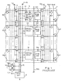
- a dynamic random access memory device embodying the present invention is fabricated on a single semiconductor chip 31, and memory cell arrays 32a and 32b are incorporated in the dynamic random access memory device.
- the memory cell arrays 32a and 32b are paired with each other for forming an array pair.
- the memory cell array 32a is implemented by a plurality of memory cells MA11, MA12,.., MA21, MA22, ..., MAm1, MAm2,... arranged in matrix
- the other memory cell array 32b is also implemented by a plurality of memory cells MB11, MB12,..., MB21, MB22,..., MBm1, MBm2 arranged in matrix.
- a storage capacitor not shown
- a plurality of bit line pairs BL1, BL2, ... and BLm are shared between the memory cell arrays 32a and 32b, and the bit lines of each pair are labeled with BLa and BLb.
- Each bit line pair BL1/ BL2/ BLm is split into a left section, an intermediate section and a right section, and the left sections and the right sections are respectively assigned to the memory cell array 32a and the memory cell array 32b.
- bit lines BLa and the bit lines BLb are alternately coupled to the bit lines BLa and the bit lines BLb, and the bit lines BLa and the bit lines BLb are further coupled to the lines of memory cells MB11/ MB21/ MBm1..., and MB12/ MB22/ MBm2.... in the right sections.
- the bit line pairs BL1 to BLm are shared between the memory cell arrays 32a and 32b, and data bits are propagated through the left or right sections between the intermediate sections and the memory cell array 32a or 32b in the form of potential difference.
- precharge/balancing circuits are coupled to the left sections and the right sections for balancing the bit line pairs at a precharge level before read-out of the data bits from selected memory cells, the precharge/balancing circuits are not shown in figure 3.
- the dynamic random access memory device further comprises a plurality sets of word lines WLa1/WLa2 and WLb1/WLb2 respectively associated with the memory cell arrays 32a and 32b for selectively coupling the memory cells MA11 to MAm2 and MB11 to MBm2 to the associated bit lines BLa and BLb.
- the word lines WLa1 and WLa2 are respectively associated with the lines of memory cells MA11/MA21/MAm1.., MA12/MA22/ MAm2,... , and the n-channel enhancement type switching transistors of the memory cells are concurrently gated by the associated word lines WLa1 and WLa2.
- the word lines WLb1 and WLb2 are respectively associated with the lines of memory cells MB11/MB21/MBm1,... and MB12/MB22/MBm2,..., and the n-channel enhancement type switching transistors of the memory cells concurrently turn on in the presence of the active high voltage level on the associated word line WLb1 or WLb2.
- the word lines WLa1/WLa2 and WLb1/WLb2 are selectively energized by a row address decoder/word line driver unit.
- the dynamic random access memory device further comprises a first transfer gate array 33a coupled between the left sections and the intermediate sections, a second transfer gate array 33b coupled between the right sections and the intermediate sections, an array of sense amplifier circuits SA1, SA2,... and SAn and a column selector or an array of switching circuits 341, 342,... and 34m coupled between a pair of data lines DL1/DL2 and a discharging line DSC.
- the first transfer gate array 33a has a plurality pairs of n-channel enhancement type switching transistors Qn11/Qn12 coupled between the left sections and the intermediate sections, and the n-channel enhancement type switching transistors Qn11/Qn12 are responsive to a first gate control signal TG1 for electrically connecting the left sections to the intermediate sections.
- the second transfer gate array 33b has a plurality pairs of n-channel enhancement type switching transistors Qn13/Qn14 coupled between the right sections and the intermediate sections, and the n-channel enhancement type switching transistors Qn13/Qn14 are concurrently gated by a second gate control signal TG2 for electrically connecting the left sections to the intermediate sections.
- the first gate control signal and the second gate control signal are selectively produced by a timing controller, and either memory cell array 32a or 32b becomes accessible.
- the sense amplifier circuits SA1 to SAm develop the potential differences on the intermediate sections of the bit line pairs BL1 to BLm through differential amplification so as to rapidly discriminating the logic level of the data bits.
- the switching circuits 341 to 34m are similar in circuit arrangement to one another, and each switching circuit comprises a parallel combination of n-channel enhancement type switching transistors Qn15/Qn16 coupled at the source nodes thereof to the data lines DL1 and DL2 and a parallel combination of n-channel enhancement type switching transistors Qn17/Qn18 coupled between the n-channel enhancement type switching transistors Qn15/Qn16 and the discharging line DSC.
- the switching circuits 341 to 34m are selectively enabled with column address decoded signals Y1, Y2,... and Ym, and the n-channel enhancement type switching transistors Qn15/Qn16 of the enabled switching circuit turn on for electrically connecting the data lines DL1 and DL2 to the associated n-channel enhancement type switching transistors Qn17/Qn18.
- the switching circuits 341 to 34m are associated with the bit line pairs BL1 to BLm, and the n-channel enhancement type switching transistors Qn17 and Qn18 of each switching circuit are gated by the bit lines BLa and BLb of the associated bit line pair.
- the bit lines BLa and BLb of each pair propagates a potential difference indicative of a data bit to the associated sense amplifier circuit so that the n-channel enhancement type switching transistors Qn17 and Qn18 selectively turn on and off.
- One of the n-channel enhancement type switching transistors Qn17 and Qn18 couples the associated data line to the discharging line DSC.
- the other of the n-channel enhancement type switching transistors Qn17 and Qn18 is turned off, and isolates the associated data line from the discharging line. As a result, a potential difference takes place between the data lines DL1 and DL2, and the potential difference on the bit line pair is transferred through the switching circuit to the data lines DL1 and DL2.
- the dynamic random access memory device further comprises a charging circuit 35 implemented by a parallel combination of p-channel enhancement type charging transistors Qp21 and Qp22.
- the p-channel enhancement type charging transistors Qp21 and Qp22 are coupled between a power voltage line Vcc and the data line DL1 and DL2, and the gate electrodes of the p-channel enhancement type charging transistors Qp21 and Qp22 are coupled to the drain nodes thereof.
- the p-channel enhancement type charging transistors Qp21 and Qp22 thus arranged supply current to the data lines DL1 and DL2, and keep the potential level at the data lines DL1 and DL2 at a certain level lower than the power voltage level by the threshold thereof in so far as the data lines DL1 and DL2 are isolated from the discharging line DSC.
- the dynamic random access memory device further comprises an output circuit 36 coupled between the data lines DL1 and DL2 and a data terminal, and the output circuit 36 produces an output data signal Dout from the potential difference on the data lines DL1 and DL2.
- the output circuit 36 serves as an interface.
- a write-in circuit is further incorporated for writing a data bit into one of the memory cells MA11-MAm2 and MB11-MBm2, the write-in circuit is not shown in figure 3.
- the dynamic random access memory device further comprises a potential control circuit 37 serving as a current control means.
- the potential control circuit 37 comprises two n-channel enhancement type discharging transistors Qn31 and Qn32 coupled in parallel between the discharging line DSC and a ground line GND.
- the gate electrode of the n-channel enhancement type discharging transistor Qn31 is coupled to the discharging line DSC, and the n-channel enhancement type discharging transistor Qn31 is turned on while the discharging line is higher than the threshold thereof. However, if the discharging line DSC reaches the threshold level of the n-channel enhancement type discharging transistor Qn31, the n-channel enhancement type discharging transistor Qn31 turns off, and isolates the discharging line DSC from the ground line GND. Thus, the n-channel enhancement type discharging transistor Qn31 serves as a diode.
- a potential control signal CV is supplied to the gate electrode of the n-channel enhancement type discharging transistor Qn32, and is supplied from the timing generator (not shown).
- the timing generator produces not only the control signals TG1/TG2/CV but also various control signals such as a precharge control signal for the precharging circuits (not shown), an activation signal for the sense amplifier circuits SA1 to SAm and an output enable signal for the output circuit 36.
- the dynamic random access memory device thus arranged selectively enters into a read-out phase for a data access, a write-in phase for rewriting the data bits in the memory cells and a refreshing phase for maintaining the data bits in the memory cells.
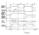
- the circuit behaviors in the write-in phase and the refreshing phase are analogous to those of the prior art, and no description is incorporated hereinbelow. For this reason, description on the circuit behavior is focused on the read-out phase with reference to figure 4 of the drawings on the assumption that the memory cell MB11 is accessed.
- Each of the data bits are delivered to the external device through a single access cycle, and each access cycle is divided into the first period T1 and the second period T2.
- An external device is assumed to supply address bits indicative of the address assigned to the memory cell MB11, and the first period T1 starts at time t1.
- the potential control signal CV is changed to the active high voltage level, and the n-channel enhancement type discharging transistor Qn32 turns on so as to pull down the discharging line DSC to the ground voltage level.
- the timing generator (not shown) changes the precharge control signal to the active level, and the precharge circuits (not shown) charge and balance the bit lines BLa and BLb.
- the timing generator keeps the gate control signals TG1 and TG2 in the inactive low voltage level, and the first and second transfer gate arrays 33a and 33b isolate the intermediate sections from the left and right sections.
- the row address decoder (not shown) changes the word line WLb1 to the active high voltage level, and the data bits stored in the storage capacitors in the form of electric charges produce potential differences on the right sections of the bit line pairs BL1 to BLm.
- the timing generator changes the gate control signal TG2 to the active high voltage level, and keeps the other gate control signal TG1 in the inactive low voltage level. As a result, only the right sections are coupled to the intermediate sections, and the potential differences are transferred to the intermediate sections.
- the timing generator (not shown) activates the sense amplifier circuits SA1 to SAm, and the sense amplifier circuits SA1 to SAm start to rapidly develop the potential differences transferred from the right sections of the bit line pairs BL1 to BLm.
- the charging circuit 35 keeps the data lines DL1 and DL2 at the certain voltage level, and the switching circuits 341 to 34m isolate the data lines DL1 and DL2 from the discharge line DSC. For this reason, the current consumption I of the charging circuit 35 is zero.
- the column address decoder (not shown) changes the column address decoded signal Y1 to the active high voltage level at time t2. However, the other column address decoded signals Y2 to Ym are maintained at the inactive low voltage level.
- the column address decoded signal Y1 allows the n-channel enhancement type switching transistors Qn15/Qn16 of the switching circuit 341 to turn on, and only the switching circuit 341 is enabled.
- the potential difference on the intermediate section of the bit line pair BL1 causes the n-channel enhancement type switching transistors Qn17 and Qn18 to turn on and off, and the data line DL1 is electrically connected through the n-channel enhancement type switching transistors Qn15 and Qn17 to the discharging line DSC.
- the n-channel enhancement type switching transistor Qn18 isolates the data line DL2 from the discharging line DSC.
- the current flows through the switching circuit 341, the discharging line DSC and the n-channel enhancement type discharging transistor Qn32 to the ground line GND, and the potential level on the data line DL1 reaches a voltage level given through a proportional distribution between the on-resistances of the field effect transistors Qp21, Qn15, Qn17 and Qn32.
- the potential level on the other data line DL2 is maintained, and the potential difference on the bit line pair BL1 is transferred to the data lines DL1 and DL2.
- the output circuit 36 produces the output data signal Dout indicative of the data bit stored in the memory cell MB11 from the potential difference between the data lines DL1 and DL2.
- the access cycle Upon production of the output data signal Dout, the access cycle enters into the second period T2 at time t3, and the potential control signal CV is recovered from the high voltage level to the low voltage level. Then, the n-channel enhancement type discharging transistor Qn32 turns off, and the discharging line DSC is recovered to the voltage level higher than the ground voltage level by the threshold Vth of the n-channel enhancement type discharging transistor Qn31. Although the current continuously flows from the data line DL1 through the n-channel enhancement type discharging transistor Qn31 into the ground line GND, the potential level on the data line DL1 is slightly lifted, and the current consumption I is decreased as shown.
- the potential control signal CV is maintained at the low voltage level unit the next access cycle starts at time t4.
- the potential control circuit 37 changes the amount of current flowing into the ground line GND, and the dynamic random access memory device improves the current consumption.
- the switching circuit is enabled as early as that of the prior art, and the access speed is not prolonged.
- the potential control circuit 37 may be replaced with a variable resistor or another appropriate circuit with variable in resistance.
Landscapes
- Engineering & Computer Science (AREA)
- Microelectronics & Electronic Packaging (AREA)
- Computer Hardware Design (AREA)
- Databases & Information Systems (AREA)
- Dram (AREA)
- Static Random-Access Memory (AREA)
Claims (6)
- Halbleiterspeichervorrichtung mit:gekennzeichnet durcha) einer Anzahl von adressierbaren Speicherzellen (MA11-MAm2/MB11-MBm2) zum Speichern von Datenbits,b) einer Anzahl von Paaren von ersten Datenleitungen (BL1-BLm), die selektiv mit der Anzahl von adressierbaren Speicherzellen verbunden sind,c) einem ersten Adress-System (WLa1-WLa2/WLb1-WLb2) zum selektiven Verbinden der Anzahl von adressierbaren Speicherzellen mit der Anzahl von Paaren von ersten Datenleitungen,d) zweiten Datenleitungen (DL1/DL2), die miteinander gepaart sind,e) einer Ladeschaltung (35), die mit den zweiten Datenleitungen verbunden sind, zum Zuführen von Strom,f) einer Entladungsleitung (DSC) zum Ableiten des Stroms,g) einem zweiten Adress-System (34) mit einer Anzahl von Schalt-Schaltungen (341/342/34m), die parallel zwischen die ersten Datenleitungen und die Entladungsleitung geschaltet sind, wobei eine der Anzahl von Schalt-Schaltungen auf ein Datenbit auf einem der Anzahl von Paaren von Datenleitungen zum selektiven Verbinden der zweiten Datenleitungen zur Entladungsleitung anspricht, wodurch das Datenbit zu den zweiten Datenleitungen in Form einer Potentialdifferenz übertragen wird, undh) einer Schnittstelle (36), die auf das Datenbit auf den zweiten Datenleitungen anspricht, zum Erzeugen eines Datensignals (Dout),
i) ein Stromsteuermittel (37), das zwischen die Entladungsleitung und eine Spannungsquelle (GND) geschaltet ist und in einer ersten Zeitspanne aktiviert wird, die dem Auslesen des Datenbits zugeordnet ist, zum Erhöhen des Stroms (I), der von der Entladungsleitung zu der Spannungsquelle fließt, zum Vergrößern der Potentialdifferenz zwischen den zweiten Datenleitungen bevor die Schnittstelle das Datensignal erzeugt, wobei das Stromsteuermittel in einer zweiten Zeitspanne des Auslesens des Datenbits deaktiviert wird, um den Strom nach Beendigung der Erzeugung des Datensignals zu vermindern. - Halbleiterspeichervorrichtung nach Anspruch 1, wobei die Stromsteuerschaltung aufweist:i-1) eine Diode (Qn31), die zwischen die Entladungsleitung und die Spannungsquelle geschaltet ist, undi-2) einen Schalt-Transistor (Qn32), der zwischen die Entladungsleitung und die Spannungsquelle parallel zu der Diode geschaltet ist und auf ein Steuersignal (CV) anspricht, um einen Stromweg zu erzeugen, bevor die Schnittstelle das Datensignal erzeugt, wobei das Steuersignal auf einen inaktiven Pegel nach Beendigung der Erzeugung des Datensignals geändert wird, so daß der Schalt-Transistor ausschaltet.
- Halbleiterspeichervorrichtung nach Anspruch 2, wobei die Diode durch einen Feld-Effekt-Transistor (Qn31) gebildet ist, dessen Source-Drain-Weg zwischen die Entladungsleitung und die Spannungsquelle geschaltet ist, wobei die Gate-Elektrode des Feld-Effekt-Transistors mit der Entladungsleitung verbunden ist.
- Halbleiterspeichervorrichtung nach Anspruch 1, wobei die Anzahl von adressierbaren Speicherzellen vom Freizugriffstyp sind, zum Speichern der Datenbits in Form von elektrischen Ladungen.
- Halbleiterspeichervorrichtung nach Anspruch 4 mit weiterhin
j) einer Anzahl von Leseverstärker-Schaltungen (SA1/SA2/SAm), die jeweils der Anzahl von Paaren der ersten Datenleitungen zugeordnet sind, zum schnellen Entwickeln von Potentialdifferenzen, die die Datenbits anzeigen, auf der Anzahl von Paaren von ersten Datenleitungen. - Halbleiterspeichervorrichtung nach Anspruch 5, wobei jedes der Anzahl von Paaren von ersten Datenleitungen in einen ersten Abschnitt aufgespaltet ist, der mit ersten Speicherzellen (MA11-MAm2) verbunden ist, die aus einer Anzah1 von adressierbaren Speicherzellen ausgewählt sind, einen zweiten Abschnitt, der mit zweiten Speicherzellen (MB11-MBm2) verbunden ist, die aus der Anzahl von adressierbaren Speicherzellen ausgewählt sind, und einen dritten Abschnitt, der zwischen dem ersten Abschnitt und dem zweiten Abschnitt vorgesehen ist und mit einer der Leseverstärker-Schaltungen (SA1-SAm) und mit einer der Schalt-Schaltungen (341-34m) verbunden ist,
wobei die Halbleiterspeichervorrichtung weiterhin aufweist:k) ein erstes Übertragungs-Gate-Array (33a), das zwischen die ersten Abschnitte der Anzahl von Paaren von ersten Datenleitungen und die dritten Abschnitte der Anzahl von Paaren von ersten Datenleitungen geschaltet ist und auf ein erstes Gate-Steuersignal (TG1) anspricht zum elektrischen Verbinden der ersten Abschnitte mit den dritten Abschnitten, undl) ein zweites Übertragungs-Gate-Array (33b), das zwischen die zweiten Abschnitte und die dritten Abschnitte geschaltet ist und auf ein zweites Gate-Steuersignal (TG2) anspricht zum elektrischen Verbinden der zweiten Abschnitte mit den dritten Abschnitten, wobei das erste Gate-Steuersignal oder das zweite Gate-Steuersignal auf einen aktiven Pegel bei jedem Datenzugriff geändert wird.
Applications Claiming Priority (3)
| Application Number | Priority Date | Filing Date | Title |
|---|---|---|---|
| JP18428593 | 1993-07-27 | ||
| JP184285/93 | 1993-07-27 | ||
| JP5184285A JP2663838B2 (ja) | 1993-07-27 | 1993-07-27 | 半導体集積回路装置 |
Publications (3)
| Publication Number | Publication Date |
|---|---|
| EP0637033A2 EP0637033A2 (de) | 1995-02-01 |
| EP0637033A3 EP0637033A3 (de) | 1996-12-04 |
| EP0637033B1 true EP0637033B1 (de) | 1999-12-22 |
Family
ID=16150652
Family Applications (1)
| Application Number | Title | Priority Date | Filing Date |
|---|---|---|---|
| EP94111639A Expired - Lifetime EP0637033B1 (de) | 1993-07-27 | 1994-07-26 | Dynamische Direktzugriffspeicheranordnung mit Spaltenauswahlschaltung mit geringem Leistungsverbrauch |
Country Status (5)
| Country | Link |
|---|---|
| US (1) | US5473576A (de) |
| EP (1) | EP0637033B1 (de) |
| JP (1) | JP2663838B2 (de) |
| KR (1) | KR0132637B1 (de) |
| DE (1) | DE69422232T2 (de) |
Families Citing this family (155)
| Publication number | Priority date | Publication date | Assignee | Title |
|---|---|---|---|---|
| US5652723A (en) * | 1991-04-18 | 1997-07-29 | Mitsubishi Denki Kabushiki Kaisha | Semiconductor memory device |
| JP3302847B2 (ja) * | 1994-12-02 | 2002-07-15 | 富士通株式会社 | 記憶装置 |
| JPH08297965A (ja) * | 1995-04-27 | 1996-11-12 | Mitsubishi Electric Corp | 半導体集積回路装置 |
| KR0177769B1 (ko) * | 1995-06-09 | 1999-04-15 | 김광호 | 고전압 소비를 최소화한 분산 드라이버 |
| KR0172368B1 (ko) * | 1995-09-29 | 1999-03-30 | 김광호 | 저전력 반도체 메모리 장치 |
| KR0157904B1 (ko) * | 1995-10-18 | 1999-02-01 | 문정환 | 메모리의 센스 증폭회로 |
| KR0166843B1 (ko) * | 1995-12-27 | 1999-02-01 | 문정환 | 저소비 전력의 디램 비트라인 선택회로 |
| US5822262A (en) * | 1996-05-25 | 1998-10-13 | Texas Instruments Incorporated | Apparatus and method for a dynamic random access memory data sensing architecture |
| US5848015A (en) * | 1996-08-08 | 1998-12-08 | Sony Corporation | Bitline precharge halt access mode for low power operation of a memory device |
| KR100207536B1 (ko) * | 1996-12-13 | 1999-07-15 | 윤종용 | 데이터 마스킹 기능을 갖는 반도체 메모리장치 |
| US5828610A (en) * | 1997-03-31 | 1998-10-27 | Seiko Epson Corporation | Low power memory including selective precharge circuit |
| US5781488A (en) * | 1997-04-18 | 1998-07-14 | Mosel Vitelic Corporation | DRAM with new I/O data path configuration |
| JPH11260057A (ja) * | 1998-03-13 | 1999-09-24 | Nec Corp | 半導体記憶装置 |
| KR100557567B1 (ko) * | 1998-10-12 | 2006-05-23 | 주식회사 하이닉스반도체 | 클램프 전류 제어 회로 |
| DE602004024683D1 (de) * | 2003-07-14 | 2010-01-28 | Fulcrum Microsystems Inc | |
| KR100761382B1 (ko) | 2006-09-29 | 2007-09-27 | 주식회사 하이닉스반도체 | 반도체 메모리 장치 |
| JP2009009665A (ja) * | 2007-06-29 | 2009-01-15 | Elpida Memory Inc | 半導体記憶装置 |
| US9158667B2 (en) | 2013-03-04 | 2015-10-13 | Micron Technology, Inc. | Apparatuses and methods for performing logical operations using sensing circuitry |
| US8964496B2 (en) * | 2013-07-26 | 2015-02-24 | Micron Technology, Inc. | Apparatuses and methods for performing compare operations using sensing circuitry |
| US8971124B1 (en) | 2013-08-08 | 2015-03-03 | Micron Technology, Inc. | Apparatuses and methods for performing logical operations using sensing circuitry |
| US9153305B2 (en) | 2013-08-30 | 2015-10-06 | Micron Technology, Inc. | Independently addressable memory array address spaces |
| US9019785B2 (en) | 2013-09-19 | 2015-04-28 | Micron Technology, Inc. | Data shifting via a number of isolation devices |
| US9449675B2 (en) | 2013-10-31 | 2016-09-20 | Micron Technology, Inc. | Apparatuses and methods for identifying an extremum value stored in an array of memory cells |
| US9430191B2 (en) | 2013-11-08 | 2016-08-30 | Micron Technology, Inc. | Division operations for memory |
| US9934856B2 (en) | 2014-03-31 | 2018-04-03 | Micron Technology, Inc. | Apparatuses and methods for comparing data patterns in memory |
| US9711207B2 (en) | 2014-06-05 | 2017-07-18 | Micron Technology, Inc. | Performing logical operations using sensing circuitry |
| US9910787B2 (en) | 2014-06-05 | 2018-03-06 | Micron Technology, Inc. | Virtual address table |
| US10074407B2 (en) | 2014-06-05 | 2018-09-11 | Micron Technology, Inc. | Apparatuses and methods for performing invert operations using sensing circuitry |
| US9496023B2 (en) | 2014-06-05 | 2016-11-15 | Micron Technology, Inc. | Comparison operations on logical representations of values in memory |
| US9786335B2 (en) | 2014-06-05 | 2017-10-10 | Micron Technology, Inc. | Apparatuses and methods for performing logical operations using sensing circuitry |
| US9455020B2 (en) | 2014-06-05 | 2016-09-27 | Micron Technology, Inc. | Apparatuses and methods for performing an exclusive or operation using sensing circuitry |
| US9779019B2 (en) | 2014-06-05 | 2017-10-03 | Micron Technology, Inc. | Data storage layout |
| US9704540B2 (en) | 2014-06-05 | 2017-07-11 | Micron Technology, Inc. | Apparatuses and methods for parity determination using sensing circuitry |
| US9711206B2 (en) | 2014-06-05 | 2017-07-18 | Micron Technology, Inc. | Performing logical operations using sensing circuitry |
| US9830999B2 (en) | 2014-06-05 | 2017-11-28 | Micron Technology, Inc. | Comparison operations in memory |
| US9449674B2 (en) | 2014-06-05 | 2016-09-20 | Micron Technology, Inc. | Performing logical operations using sensing circuitry |
| US9589602B2 (en) | 2014-09-03 | 2017-03-07 | Micron Technology, Inc. | Comparison operations in memory |
| US9898252B2 (en) | 2014-09-03 | 2018-02-20 | Micron Technology, Inc. | Multiplication operations in memory |
| US9747961B2 (en) | 2014-09-03 | 2017-08-29 | Micron Technology, Inc. | Division operations in memory |
| US9847110B2 (en) | 2014-09-03 | 2017-12-19 | Micron Technology, Inc. | Apparatuses and methods for storing a data value in multiple columns of an array corresponding to digits of a vector |
| US9740607B2 (en) | 2014-09-03 | 2017-08-22 | Micron Technology, Inc. | Swap operations in memory |
| US10068652B2 (en) | 2014-09-03 | 2018-09-04 | Micron Technology, Inc. | Apparatuses and methods for determining population count |
| US9904515B2 (en) | 2014-09-03 | 2018-02-27 | Micron Technology, Inc. | Multiplication operations in memory |
| US9940026B2 (en) | 2014-10-03 | 2018-04-10 | Micron Technology, Inc. | Multidimensional contiguous memory allocation |
| US9836218B2 (en) | 2014-10-03 | 2017-12-05 | Micron Technology, Inc. | Computing reduction and prefix sum operations in memory |
| US10163467B2 (en) | 2014-10-16 | 2018-12-25 | Micron Technology, Inc. | Multiple endianness compatibility |
| US10147480B2 (en) | 2014-10-24 | 2018-12-04 | Micron Technology, Inc. | Sort operation in memory |
| US9779784B2 (en) | 2014-10-29 | 2017-10-03 | Micron Technology, Inc. | Apparatuses and methods for performing logical operations using sensing circuitry |
| US10073635B2 (en) | 2014-12-01 | 2018-09-11 | Micron Technology, Inc. | Multiple endianness compatibility |
| US9747960B2 (en) | 2014-12-01 | 2017-08-29 | Micron Technology, Inc. | Apparatuses and methods for converting a mask to an index |
| US10061590B2 (en) | 2015-01-07 | 2018-08-28 | Micron Technology, Inc. | Generating and executing a control flow |
| US10032493B2 (en) | 2015-01-07 | 2018-07-24 | Micron Technology, Inc. | Longest element length determination in memory |
| US9583163B2 (en) | 2015-02-03 | 2017-02-28 | Micron Technology, Inc. | Loop structure for operations in memory |
| CN107408405B (zh) | 2015-02-06 | 2021-03-05 | 美光科技公司 | 用于并行写入到多个存储器装置位置的设备及方法 |
| WO2016126478A1 (en) | 2015-02-06 | 2016-08-11 | Micron Technology, Inc. | Apparatuses and methods for memory device as a store for program instructions |
| WO2016126472A1 (en) | 2015-02-06 | 2016-08-11 | Micron Technology, Inc. | Apparatuses and methods for scatter and gather |
| WO2016144724A1 (en) | 2015-03-10 | 2016-09-15 | Micron Technology, Inc. | Apparatuses and methods for shift decisions |
| US9898253B2 (en) | 2015-03-11 | 2018-02-20 | Micron Technology, Inc. | Division operations on variable length elements in memory |
| US9741399B2 (en) | 2015-03-11 | 2017-08-22 | Micron Technology, Inc. | Data shift by elements of a vector in memory |
| WO2016144726A1 (en) | 2015-03-12 | 2016-09-15 | Micron Technology, Inc. | Apparatuses and methods for data movement |
| US10146537B2 (en) | 2015-03-13 | 2018-12-04 | Micron Technology, Inc. | Vector population count determination in memory |
| US10049054B2 (en) | 2015-04-01 | 2018-08-14 | Micron Technology, Inc. | Virtual register file |
| US10140104B2 (en) | 2015-04-14 | 2018-11-27 | Micron Technology, Inc. | Target architecture determination |
| US9959923B2 (en) | 2015-04-16 | 2018-05-01 | Micron Technology, Inc. | Apparatuses and methods to reverse data stored in memory |
| US10073786B2 (en) | 2015-05-28 | 2018-09-11 | Micron Technology, Inc. | Apparatuses and methods for compute enabled cache |
| US9704541B2 (en) | 2015-06-12 | 2017-07-11 | Micron Technology, Inc. | Simulating access lines |
| US9921777B2 (en) | 2015-06-22 | 2018-03-20 | Micron Technology, Inc. | Apparatuses and methods for data transfer from sensing circuitry to a controller |
| US9996479B2 (en) | 2015-08-17 | 2018-06-12 | Micron Technology, Inc. | Encryption of executables in computational memory |
| US9905276B2 (en) | 2015-12-21 | 2018-02-27 | Micron Technology, Inc. | Control of sensing components in association with performing operations |
| US9952925B2 (en) | 2016-01-06 | 2018-04-24 | Micron Technology, Inc. | Error code calculation on sensing circuitry |
| US10048888B2 (en) | 2016-02-10 | 2018-08-14 | Micron Technology, Inc. | Apparatuses and methods for partitioned parallel data movement |
| US9892767B2 (en) | 2016-02-12 | 2018-02-13 | Micron Technology, Inc. | Data gathering in memory |
| US9971541B2 (en) | 2016-02-17 | 2018-05-15 | Micron Technology, Inc. | Apparatuses and methods for data movement |
| US10956439B2 (en) | 2016-02-19 | 2021-03-23 | Micron Technology, Inc. | Data transfer with a bit vector operation device |
| US9899070B2 (en) | 2016-02-19 | 2018-02-20 | Micron Technology, Inc. | Modified decode for corner turn |
| US9697876B1 (en) | 2016-03-01 | 2017-07-04 | Micron Technology, Inc. | Vertical bit vector shift in memory |
| US10262721B2 (en) | 2016-03-10 | 2019-04-16 | Micron Technology, Inc. | Apparatuses and methods for cache invalidate |
| US9997232B2 (en) | 2016-03-10 | 2018-06-12 | Micron Technology, Inc. | Processing in memory (PIM) capable memory device having sensing circuitry performing logic operations |
| US10379772B2 (en) | 2016-03-16 | 2019-08-13 | Micron Technology, Inc. | Apparatuses and methods for operations using compressed and decompressed data |
| US9910637B2 (en) | 2016-03-17 | 2018-03-06 | Micron Technology, Inc. | Signed division in memory |
| US10388393B2 (en) | 2016-03-22 | 2019-08-20 | Micron Technology, Inc. | Apparatus and methods for debugging on a host and memory device |
| US11074988B2 (en) | 2016-03-22 | 2021-07-27 | Micron Technology, Inc. | Apparatus and methods for debugging on a host and memory device |
| US10120740B2 (en) | 2016-03-22 | 2018-11-06 | Micron Technology, Inc. | Apparatus and methods for debugging on a memory device |
| US10474581B2 (en) | 2016-03-25 | 2019-11-12 | Micron Technology, Inc. | Apparatuses and methods for cache operations |
| US10977033B2 (en) | 2016-03-25 | 2021-04-13 | Micron Technology, Inc. | Mask patterns generated in memory from seed vectors |
| US10430244B2 (en) | 2016-03-28 | 2019-10-01 | Micron Technology, Inc. | Apparatuses and methods to determine timing of operations |
| US10074416B2 (en) | 2016-03-28 | 2018-09-11 | Micron Technology, Inc. | Apparatuses and methods for data movement |
| US10453502B2 (en) | 2016-04-04 | 2019-10-22 | Micron Technology, Inc. | Memory bank power coordination including concurrently performing a memory operation in a selected number of memory regions |
| US10607665B2 (en) | 2016-04-07 | 2020-03-31 | Micron Technology, Inc. | Span mask generation |
| US9818459B2 (en) | 2016-04-19 | 2017-11-14 | Micron Technology, Inc. | Invert operations using sensing circuitry |
| US10153008B2 (en) | 2016-04-20 | 2018-12-11 | Micron Technology, Inc. | Apparatuses and methods for performing corner turn operations using sensing circuitry |
| US9659605B1 (en) | 2016-04-20 | 2017-05-23 | Micron Technology, Inc. | Apparatuses and methods for performing corner turn operations using sensing circuitry |
| US10042608B2 (en) | 2016-05-11 | 2018-08-07 | Micron Technology, Inc. | Signed division in memory |
| US9659610B1 (en) | 2016-05-18 | 2017-05-23 | Micron Technology, Inc. | Apparatuses and methods for shifting data |
| US10049707B2 (en) | 2016-06-03 | 2018-08-14 | Micron Technology, Inc. | Shifting data |
| US10387046B2 (en) | 2016-06-22 | 2019-08-20 | Micron Technology, Inc. | Bank to bank data transfer |
| US10037785B2 (en) | 2016-07-08 | 2018-07-31 | Micron Technology, Inc. | Scan chain operation in sensing circuitry |
| US10388360B2 (en) | 2016-07-19 | 2019-08-20 | Micron Technology, Inc. | Utilization of data stored in an edge section of an array |
| US10733089B2 (en) | 2016-07-20 | 2020-08-04 | Micron Technology, Inc. | Apparatuses and methods for write address tracking |
| US10387299B2 (en) | 2016-07-20 | 2019-08-20 | Micron Technology, Inc. | Apparatuses and methods for transferring data |
| US9767864B1 (en) | 2016-07-21 | 2017-09-19 | Micron Technology, Inc. | Apparatuses and methods for storing a data value in a sensing circuitry element |
| US9972367B2 (en) | 2016-07-21 | 2018-05-15 | Micron Technology, Inc. | Shifting data in sensing circuitry |
| US10303632B2 (en) | 2016-07-26 | 2019-05-28 | Micron Technology, Inc. | Accessing status information |
| US10468087B2 (en) | 2016-07-28 | 2019-11-05 | Micron Technology, Inc. | Apparatuses and methods for operations in a self-refresh state |
| US9990181B2 (en) | 2016-08-03 | 2018-06-05 | Micron Technology, Inc. | Apparatuses and methods for random number generation |
| US11029951B2 (en) | 2016-08-15 | 2021-06-08 | Micron Technology, Inc. | Smallest or largest value element determination |
| US10606587B2 (en) | 2016-08-24 | 2020-03-31 | Micron Technology, Inc. | Apparatus and methods related to microcode instructions indicating instruction types |
| US10466928B2 (en) | 2016-09-15 | 2019-11-05 | Micron Technology, Inc. | Updating a register in memory |
| US10387058B2 (en) | 2016-09-29 | 2019-08-20 | Micron Technology, Inc. | Apparatuses and methods to change data category values |
| US10014034B2 (en) | 2016-10-06 | 2018-07-03 | Micron Technology, Inc. | Shifting data in sensing circuitry |
| US10529409B2 (en) | 2016-10-13 | 2020-01-07 | Micron Technology, Inc. | Apparatuses and methods to perform logical operations using sensing circuitry |
| US9805772B1 (en) | 2016-10-20 | 2017-10-31 | Micron Technology, Inc. | Apparatuses and methods to selectively perform logical operations |
| CN207637499U (zh) | 2016-11-08 | 2018-07-20 | 美光科技公司 | 用于形成在存储器单元阵列上方的计算组件的设备 |
| US10423353B2 (en) | 2016-11-11 | 2019-09-24 | Micron Technology, Inc. | Apparatuses and methods for memory alignment |
| US9761300B1 (en) | 2016-11-22 | 2017-09-12 | Micron Technology, Inc. | Data shift apparatuses and methods |
| US10402340B2 (en) | 2017-02-21 | 2019-09-03 | Micron Technology, Inc. | Memory array page table walk |
| US10268389B2 (en) | 2017-02-22 | 2019-04-23 | Micron Technology, Inc. | Apparatuses and methods for in-memory operations |
| US10403352B2 (en) | 2017-02-22 | 2019-09-03 | Micron Technology, Inc. | Apparatuses and methods for compute in data path |
| US10838899B2 (en) | 2017-03-21 | 2020-11-17 | Micron Technology, Inc. | Apparatuses and methods for in-memory data switching networks |
| US11222260B2 (en) | 2017-03-22 | 2022-01-11 | Micron Technology, Inc. | Apparatuses and methods for operating neural networks |
| US10185674B2 (en) | 2017-03-22 | 2019-01-22 | Micron Technology, Inc. | Apparatus and methods for in data path compute operations |
| US10049721B1 (en) | 2017-03-27 | 2018-08-14 | Micron Technology, Inc. | Apparatuses and methods for in-memory operations |
| US10147467B2 (en) | 2017-04-17 | 2018-12-04 | Micron Technology, Inc. | Element value comparison in memory |
| US10043570B1 (en) | 2017-04-17 | 2018-08-07 | Micron Technology, Inc. | Signed element compare in memory |
| US9997212B1 (en) | 2017-04-24 | 2018-06-12 | Micron Technology, Inc. | Accessing data in memory |
| US10942843B2 (en) | 2017-04-25 | 2021-03-09 | Micron Technology, Inc. | Storing data elements of different lengths in respective adjacent rows or columns according to memory shapes |
| US10236038B2 (en) | 2017-05-15 | 2019-03-19 | Micron Technology, Inc. | Bank to bank data transfer |
| US10068664B1 (en) | 2017-05-19 | 2018-09-04 | Micron Technology, Inc. | Column repair in memory |
| US10013197B1 (en) | 2017-06-01 | 2018-07-03 | Micron Technology, Inc. | Shift skip |
| US10262701B2 (en) | 2017-06-07 | 2019-04-16 | Micron Technology, Inc. | Data transfer between subarrays in memory |
| US10152271B1 (en) | 2017-06-07 | 2018-12-11 | Micron Technology, Inc. | Data replication |
| US10318168B2 (en) | 2017-06-19 | 2019-06-11 | Micron Technology, Inc. | Apparatuses and methods for simultaneous in data path compute operations |
| US10162005B1 (en) | 2017-08-09 | 2018-12-25 | Micron Technology, Inc. | Scan chain operations |
| US10534553B2 (en) | 2017-08-30 | 2020-01-14 | Micron Technology, Inc. | Memory array accessibility |
| US10416927B2 (en) | 2017-08-31 | 2019-09-17 | Micron Technology, Inc. | Processing in memory |
| US10741239B2 (en) | 2017-08-31 | 2020-08-11 | Micron Technology, Inc. | Processing in memory device including a row address strobe manager |
| US10346092B2 (en) | 2017-08-31 | 2019-07-09 | Micron Technology, Inc. | Apparatuses and methods for in-memory operations using timing circuitry |
| US10409739B2 (en) | 2017-10-24 | 2019-09-10 | Micron Technology, Inc. | Command selection policy |
| US10522210B2 (en) | 2017-12-14 | 2019-12-31 | Micron Technology, Inc. | Apparatuses and methods for subarray addressing |
| US10332586B1 (en) | 2017-12-19 | 2019-06-25 | Micron Technology, Inc. | Apparatuses and methods for subrow addressing |
| US10614875B2 (en) | 2018-01-30 | 2020-04-07 | Micron Technology, Inc. | Logical operations using memory cells |
| US10437557B2 (en) | 2018-01-31 | 2019-10-08 | Micron Technology, Inc. | Determination of a match between data values stored by several arrays |
| US11194477B2 (en) | 2018-01-31 | 2021-12-07 | Micron Technology, Inc. | Determination of a match between data values stored by three or more arrays |
| US10725696B2 (en) | 2018-04-12 | 2020-07-28 | Micron Technology, Inc. | Command selection policy with read priority |
| US10440341B1 (en) | 2018-06-07 | 2019-10-08 | Micron Technology, Inc. | Image processor formed in an array of memory cells |
| US11175915B2 (en) | 2018-10-10 | 2021-11-16 | Micron Technology, Inc. | Vector registers implemented in memory |
| US10769071B2 (en) | 2018-10-10 | 2020-09-08 | Micron Technology, Inc. | Coherent memory access |
| US10483978B1 (en) | 2018-10-16 | 2019-11-19 | Micron Technology, Inc. | Memory device processing |
| US11184446B2 (en) | 2018-12-05 | 2021-11-23 | Micron Technology, Inc. | Methods and apparatus for incentivizing participation in fog networks |
| US12118056B2 (en) | 2019-05-03 | 2024-10-15 | Micron Technology, Inc. | Methods and apparatus for performing matrix transformations within a memory array |
| US10867655B1 (en) | 2019-07-08 | 2020-12-15 | Micron Technology, Inc. | Methods and apparatus for dynamically adjusting performance of partitioned memory |
| US11360768B2 (en) | 2019-08-14 | 2022-06-14 | Micron Technolgy, Inc. | Bit string operations in memory |
| US11449577B2 (en) | 2019-11-20 | 2022-09-20 | Micron Technology, Inc. | Methods and apparatus for performing video processing matrix operations within a memory array |
| US11853385B2 (en) | 2019-12-05 | 2023-12-26 | Micron Technology, Inc. | Methods and apparatus for performing diversity matrix operations within a memory array |
| US11227641B1 (en) | 2020-07-21 | 2022-01-18 | Micron Technology, Inc. | Arithmetic operations in memory |
Family Cites Families (11)
| Publication number | Priority date | Publication date | Assignee | Title |
|---|---|---|---|---|
| JPS62250595A (ja) * | 1986-04-23 | 1987-10-31 | Hitachi Vlsi Eng Corp | 半導体記憶装置 |
| US5245582A (en) * | 1987-10-27 | 1993-09-14 | Mitsubishi Denki Kabushiki Kaisha | Memory card circuit with power-down control of access buffer |
| JPH01147915A (ja) * | 1987-12-04 | 1989-06-09 | Hitachi Ltd | 半導体回路 |
| US4954992A (en) * | 1987-12-24 | 1990-09-04 | Mitsubishi Denki Kabushiki Kaisha | Random access memory having separate read out and write in bus lines for reduced access time and operating method therefor |
| JP2878713B2 (ja) * | 1989-06-13 | 1999-04-05 | 株式会社東芝 | 半導体記憶装置 |
| JPH03283179A (ja) * | 1990-03-30 | 1991-12-13 | Fujitsu Ltd | 半導体記憶装置 |
| JP3101298B2 (ja) * | 1990-03-30 | 2000-10-23 | 株式会社東芝 | 半導体メモリ装置 |
| JPH04188493A (ja) * | 1990-11-22 | 1992-07-07 | Mitsubishi Electric Corp | 半導体ダイナミックram |
| JP3096314B2 (ja) * | 1991-04-10 | 2000-10-10 | 沖電気工業株式会社 | 半導体記憶装置 |
| KR940007639B1 (ko) * | 1991-07-23 | 1994-08-22 | 삼성전자 주식회사 | 분할된 입출력 라인을 갖는 데이타 전송회로 |
| US5283760A (en) * | 1991-08-14 | 1994-02-01 | Samsung Electronics Co., Ltd. | Data transmission circuit |
-
1993
- 1993-07-27 JP JP5184285A patent/JP2663838B2/ja not_active Expired - Fee Related
-
1994
- 1994-07-26 EP EP94111639A patent/EP0637033B1/de not_active Expired - Lifetime
- 1994-07-26 DE DE69422232T patent/DE69422232T2/de not_active Expired - Fee Related
- 1994-07-27 US US08/281,278 patent/US5473576A/en not_active Expired - Fee Related
- 1994-07-27 KR KR1019940018234A patent/KR0132637B1/ko not_active Expired - Fee Related
Also Published As
| Publication number | Publication date |
|---|---|
| EP0637033A2 (de) | 1995-02-01 |
| JP2663838B2 (ja) | 1997-10-15 |
| DE69422232D1 (de) | 2000-01-27 |
| DE69422232T2 (de) | 2000-09-07 |
| KR0132637B1 (ko) | 1998-04-16 |
| EP0637033A3 (de) | 1996-12-04 |
| JPH0745076A (ja) | 1995-02-14 |
| KR950004279A (ko) | 1995-02-17 |
| US5473576A (en) | 1995-12-05 |
Similar Documents
| Publication | Publication Date | Title |
|---|---|---|
| EP0637033B1 (de) | Dynamische Direktzugriffspeicheranordnung mit Spaltenauswahlschaltung mit geringem Leistungsverbrauch | |
| US6205071B1 (en) | Semiconductor memory device including sense amplifier circuit differing in drivability between data write mode and data read mode | |
| KR970005283B1 (ko) | 반도체 기억장치 | |
| US6552944B2 (en) | Single bitline direct sensing architecture for high speed memory device | |
| US5815451A (en) | Dynamic semiconductor memory device having a precharge circuit using low power consumption | |
| US6678198B2 (en) | Pseudo differential sensing method and apparatus for DRAM cell | |
| US5430672A (en) | Dynamic random access memory device having one-transistor one-capacitor type memory cells coupled between bit lines paired with each other | |
| JPH02252196A (ja) | 単一トランジスタメモリセルと共に使用する高速差動センスアンプ | |
| US5881006A (en) | Semiconductor memory device | |
| KR0150013B1 (ko) | 반도체 메모리 디바이스 | |
| JP2004079141A (ja) | 半導体メモリ装置 | |
| US6301175B1 (en) | Memory device with single-ended sensing and low voltage pre-charge | |
| US5418753A (en) | Dynamic random access memory device incorporating transfer gates between memory cell array and sense amplifier enabled in standard modes only | |
| KR960009948B1 (ko) | 랜덤 액세스 메모리 | |
| JP2980368B2 (ja) | ダイナミック型半導体記憶装置 | |
| JPS61158094A (ja) | ダイナミツク型メモリのセンスアンプ駆動回路 | |
| KR960015210B1 (ko) | 반도체 메모리 장치 | |
| US6466508B1 (en) | Semiconductor memory device having high-speed read function | |
| US7142446B2 (en) | Apparatus and method to reduce undesirable effects caused by a fault in a memory device | |
| KR101317874B1 (ko) | 불휘발성 기억장치 및 그 판독방법 | |
| JP3540777B2 (ja) | 不揮発性半導体記憶装置 | |
| US6212120B1 (en) | Semiconductor memory device with less power consumption | |
| US5331595A (en) | Semiconductor memory device having IO line pair to be equalized and divided into blocks and operating method thereof | |
| JP2001307479A (ja) | 半導体集積回路装置 | |
| US6434069B1 (en) | Two-phase charge-sharing data latch for memory circuit |
Legal Events
| Date | Code | Title | Description |
|---|---|---|---|
| PUAI | Public reference made under article 153(3) epc to a published international application that has entered the european phase |
Free format text: ORIGINAL CODE: 0009012 |
|
| AK | Designated contracting states |
Kind code of ref document: A2 Designated state(s): DE FR GB |
|
| PUAL | Search report despatched |
Free format text: ORIGINAL CODE: 0009013 |
|
| AK | Designated contracting states |
Kind code of ref document: A3 Designated state(s): DE FR GB |
|
| 17P | Request for examination filed |
Effective date: 19961022 |
|
| 17Q | First examination report despatched |
Effective date: 19981102 |
|
| GRAG | Despatch of communication of intention to grant |
Free format text: ORIGINAL CODE: EPIDOS AGRA |
|
| GRAG | Despatch of communication of intention to grant |
Free format text: ORIGINAL CODE: EPIDOS AGRA |
|
| GRAH | Despatch of communication of intention to grant a patent |
Free format text: ORIGINAL CODE: EPIDOS IGRA |
|
| GRAH | Despatch of communication of intention to grant a patent |
Free format text: ORIGINAL CODE: EPIDOS IGRA |
|
| GRAA | (expected) grant |
Free format text: ORIGINAL CODE: 0009210 |
|
| AK | Designated contracting states |
Kind code of ref document: B1 Designated state(s): DE FR GB |
|
| REF | Corresponds to: |
Ref document number: 69422232 Country of ref document: DE Date of ref document: 20000127 |
|
| ET | Fr: translation filed | ||
| PLBE | No opposition filed within time limit |
Free format text: ORIGINAL CODE: 0009261 |
|
| STAA | Information on the status of an ep patent application or granted ep patent |
Free format text: STATUS: NO OPPOSITION FILED WITHIN TIME LIMIT |
|
| 26N | No opposition filed | ||
| PGFP | Annual fee paid to national office [announced via postgrant information from national office to epo] |
Ref country code: FR Payment date: 20010712 Year of fee payment: 8 |
|
| PGFP | Annual fee paid to national office [announced via postgrant information from national office to epo] |
Ref country code: GB Payment date: 20010725 Year of fee payment: 8 |
|
| REG | Reference to a national code |
Ref country code: GB Ref legal event code: IF02 |
|
| PG25 | Lapsed in a contracting state [announced via postgrant information from national office to epo] |
Ref country code: GB Free format text: LAPSE BECAUSE OF NON-PAYMENT OF DUE FEES Effective date: 20020726 |
|
| GBPC | Gb: european patent ceased through non-payment of renewal fee |
Effective date: 20020726 |
|
| PG25 | Lapsed in a contracting state [announced via postgrant information from national office to epo] |
Ref country code: FR Free format text: LAPSE BECAUSE OF NON-PAYMENT OF DUE FEES Effective date: 20030331 |
|
| REG | Reference to a national code |
Ref country code: FR Ref legal event code: ST |
|
| PGFP | Annual fee paid to national office [announced via postgrant information from national office to epo] |
Ref country code: DE Payment date: 20030807 Year of fee payment: 10 |
|
| PG25 | Lapsed in a contracting state [announced via postgrant information from national office to epo] |
Ref country code: DE Free format text: LAPSE BECAUSE OF NON-PAYMENT OF DUE FEES Effective date: 20050201 |