EP0637109B1 - Optischer Faserverstärker aus dotiertem Fluoridglas und Verfahren zu seiner Herstellung - Google Patents
Optischer Faserverstärker aus dotiertem Fluoridglas und Verfahren zu seiner Herstellung Download PDFInfo
- Publication number
- EP0637109B1 EP0637109B1 EP94401706A EP94401706A EP0637109B1 EP 0637109 B1 EP0637109 B1 EP 0637109B1 EP 94401706 A EP94401706 A EP 94401706A EP 94401706 A EP94401706 A EP 94401706A EP 0637109 B1 EP0637109 B1 EP 0637109B1
- Authority
- EP
- European Patent Office
- Prior art keywords
- fibre
- optical
- silica
- fluoride glass
- doped
- Prior art date
- Legal status (The legal status is an assumption and is not a legal conclusion. Google has not performed a legal analysis and makes no representation as to the accuracy of the status listed.)
- Expired - Lifetime
Links
- 230000003287 optical effect Effects 0.000 title claims description 57
- 238000004519 manufacturing process Methods 0.000 title claims description 11
- 238000000034 method Methods 0.000 title claims description 9
- 239000003365 glass fiber Substances 0.000 title description 24
- KRHYYFGTRYWZRS-UHFFFAOYSA-M Fluoride anion Chemical compound [F-] KRHYYFGTRYWZRS-UHFFFAOYSA-M 0.000 title 1
- VYPSYNLAJGMNEJ-UHFFFAOYSA-N Silicium dioxide Chemical compound O=[Si]=O VYPSYNLAJGMNEJ-UHFFFAOYSA-N 0.000 claims description 149
- 239000000835 fiber Substances 0.000 claims description 110
- 239000013307 optical fiber Substances 0.000 claims description 75
- 239000000377 silicon dioxide Substances 0.000 claims description 75
- 238000005086 pumping Methods 0.000 claims description 28
- 239000005383 fluoride glass Substances 0.000 claims description 21
- 230000005855 radiation Effects 0.000 claims description 12
- 230000008878 coupling Effects 0.000 claims description 11
- 238000010168 coupling process Methods 0.000 claims description 11
- 238000005859 coupling reaction Methods 0.000 claims description 11
- 150000002500 ions Chemical class 0.000 claims description 7
- 229910052761 rare earth metal Inorganic materials 0.000 claims description 6
- 150000002910 rare earth metals Chemical class 0.000 claims description 6
- 239000011521 glass Substances 0.000 description 32
- 241001639412 Verres Species 0.000 description 15
- 230000004927 fusion Effects 0.000 description 9
- 229910052691 Erbium Inorganic materials 0.000 description 4
- UYAHIZSMUZPPFV-UHFFFAOYSA-N erbium Chemical compound [Er] UYAHIZSMUZPPFV-UHFFFAOYSA-N 0.000 description 4
- 229910052777 Praseodymium Inorganic materials 0.000 description 3
- -1 praseodymium ions Chemical class 0.000 description 3
- 230000007704 transition Effects 0.000 description 3
- 235000021183 entrée Nutrition 0.000 description 2
- 238000005304 joining Methods 0.000 description 2
- PUDIUYLPXJFUGB-UHFFFAOYSA-N praseodymium atom Chemical compound [Pr] PUDIUYLPXJFUGB-UHFFFAOYSA-N 0.000 description 2
- 238000001228 spectrum Methods 0.000 description 2
- 239000005371 ZBLAN Substances 0.000 description 1
- 230000006978 adaptation Effects 0.000 description 1
- 230000003321 amplification Effects 0.000 description 1
- 230000005540 biological transmission Effects 0.000 description 1
- 238000009826 distribution Methods 0.000 description 1
- 238000005516 engineering process Methods 0.000 description 1
- 238000000605 extraction Methods 0.000 description 1
- 238000001914 filtration Methods 0.000 description 1
- 238000003780 insertion Methods 0.000 description 1
- 230000037431 insertion Effects 0.000 description 1
- 238000002844 melting Methods 0.000 description 1
- 230000008018 melting Effects 0.000 description 1
- 238000012544 monitoring process Methods 0.000 description 1
- 238000003199 nucleic acid amplification method Methods 0.000 description 1
- 229910000679 solder Inorganic materials 0.000 description 1
- 230000003595 spectral effect Effects 0.000 description 1
- 230000002269 spontaneous effect Effects 0.000 description 1
- 238000003466 welding Methods 0.000 description 1
Images
Classifications
-
- H—ELECTRICITY
- H01—ELECTRIC ELEMENTS
- H01S—DEVICES USING THE PROCESS OF LIGHT AMPLIFICATION BY STIMULATED EMISSION OF RADIATION [LASER] TO AMPLIFY OR GENERATE LIGHT; DEVICES USING STIMULATED EMISSION OF ELECTROMAGNETIC RADIATION IN WAVE RANGES OTHER THAN OPTICAL
- H01S3/00—Lasers, i.e. devices using stimulated emission of electromagnetic radiation in the infrared, visible or ultraviolet wave range
- H01S3/05—Construction or shape of optical resonators; Accommodation of active medium therein; Shape of active medium
- H01S3/06—Construction or shape of active medium
- H01S3/063—Waveguide lasers, i.e. whereby the dimensions of the waveguide are of the order of the light wavelength
- H01S3/067—Fibre lasers
- H01S3/06754—Fibre amplifiers
-
- G—PHYSICS
- G02—OPTICS
- G02B—OPTICAL ELEMENTS, SYSTEMS OR APPARATUS
- G02B6/00—Light guides; Structural details of arrangements comprising light guides and other optical elements, e.g. couplings
- G02B6/24—Coupling light guides
- G02B6/26—Optical coupling means
- G02B6/28—Optical coupling means having data bus means, i.e. plural waveguides interconnected and providing an inherently bidirectional system by mixing and splitting signals
- G02B6/2804—Optical coupling means having data bus means, i.e. plural waveguides interconnected and providing an inherently bidirectional system by mixing and splitting signals forming multipart couplers without wavelength selective elements, e.g. "T" couplers, star couplers
-
- H—ELECTRICITY
- H01—ELECTRIC ELEMENTS
- H01S—DEVICES USING THE PROCESS OF LIGHT AMPLIFICATION BY STIMULATED EMISSION OF RADIATION [LASER] TO AMPLIFY OR GENERATE LIGHT; DEVICES USING STIMULATED EMISSION OF ELECTROMAGNETIC RADIATION IN WAVE RANGES OTHER THAN OPTICAL
- H01S3/00—Lasers, i.e. devices using stimulated emission of electromagnetic radiation in the infrared, visible or ultraviolet wave range
- H01S3/14—Lasers, i.e. devices using stimulated emission of electromagnetic radiation in the infrared, visible or ultraviolet wave range characterised by the material used as the active medium
- H01S3/16—Solid materials
- H01S3/17—Solid materials amorphous, e.g. glass
- H01S3/173—Solid materials amorphous, e.g. glass fluoride glass, e.g. fluorozirconate or ZBLAN [ ZrF4-BaF2-LaF3-AlF3-NaF]
Definitions
- the present invention relates to an optical fiber optic amplifier made of doped fluorinated glass and a method of manufacturing this amplifier.
- optical fiber amplifiers doped with a rare earth can be used to make telecommunications systems, both in transmission and in distribution.
- Erbium-doped silica fiber optical amplifier has been the most studied.
- Fluorinated glass fibers are now commercially available and it has been shown that doping the core of such fibers with erbium (respectively praseodymium) makes it possible to amplify radiation whose wavelength is close to 1.5 ⁇ m (respectively 1.3 ⁇ m).
- This property is interesting for transmitting a wavelength multiplex and several methods have been proposed for "flattening" the gain spectrum of amplifiers produced using doped silica fibers.
- fluorinated glass fibers doped with erbium is the simplest solution for producing optical amplifiers with flat spectral gain.
- the only fiber optic amplifier that can function properly at present is a fiber amplifier made of fluoride glass doped with praseodymium.
- these amplifiers based on fluorinated glass fibers must be inserted between two ends of optical fibers in silica and it is important that the input and the output of these amplifiers are wired in standard optical fibers of silica ( CCITT recommendation G652).
- a known solution consists in joining a fluorinated glass fiber and a standard silica fiber by means of a connector.
- a fluorinated glass fiber for example of the type of the OPTABALL system (registered trademark) marketed by the company Radial, whose dynamic losses can be adjusted.
- an optical amplifier comprising an optical fiber made of doped fluorinated glass, which is connected, on one side, to a silica fiber by means of such a connector (input connector) and, from the on the other hand, to another silica fiber by a connector of the same type (output connector).
- the reduction in the size of the optical mode in the doped fluorinated glass fiber causes intolerable losses when injecting the pumping radiation and the signal to be amplified, through the input connector, and upon extraction of the amplified signal, through the output connector of the doped fluorinated glass fiber.
- the adaptation of the optical mode diameter between the standard silica fiber and the doped fluorinated glass fiber can be improved by using an intermediate silica fiber having the same mode diameter as the doped fluorinated glass fiber, this intermediate fiber being welded by fusion with standard fiber on one side and bonded with fluorinated glass fiber doped on the other side.
- Fusion welding of the two silica fibers gives losses typically less than 0.3 dB while bonding of the silica fiber to the doped fluorinated glass fiber is carried out with losses typically less than 0.4 dB.
- the aim of the present invention is to remedy these drawbacks by proposing an optical amplifier with optical fiber made of doped fluorinated glass and a method of manufacturing this amplifier which make it possible both to minimize the coupling losses to the fiber made of doped fluorinated glass, to avoid the problems due to bonding which have been mentioned above and to have an input and an output of the optical amplifier made of standard silica optical fibers.
- optical fiber made of fluorinated glass doped so as to be able to amplify a light signal one understands an optical fiber whose core is made of fluorinated glass suitably doped to constitute an amplifying medium with respect to the signal .
- this fluorinated glass core is for example doped with erbium or praseodymium ions.
- the optical coupling means is another 2 to 1 type optical multiplexer which comprises, on the one hand, two optical fibers made of silica and, on the other hand , fluorinated glass fiber.
- An optical amplifier with a symmetrical structure is thus obtained, with inputs and outputs on silica fibers.
- the core of said optical fiber section can be doped with ions of at least one rare earth.
- the optical fiber made of fluorinated glass is doped over its entire length.
- the fluorinated glass optical fiber comprises a section of fluorinated glass optical fiber doped so as to be able to amplify the light signal and, on both sides of this section, two other sections of optical fiber made of undoped fluorinated glass.
- a standard silica optical fiber is welded to each of said silica optical fibers and another standard silica optical fiber to said other silica optical fiber, the diameter of mode of the fluorinated glass optical fiber being equal to the mode diameter of said silica optical fibers and of said other silica optical fiber and less than the mode diameter of standard silica fibers.
- the ends of the fluorinated glass fiber are polished perpendicular or oblique to its axis.
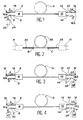
- the optical amplifier according to the invention is inserted into an optical line constituted by an optical fiber 16 of standard silica in which an optical signal S propagates.
- the optical fiber 16 is interrupted for the insertion of this optical amplifier.
- a part 16a of the fiber 16 is optically coupled to the optical fiber 6 of this amplifier by a fusion weld 18 and the other part 16b of this optical fiber 16 is optically coupled to the optical fiber 12 of the amplifier by a solder by merger 20.
- the optical amplifier of FIG. 1 is also fitted with a pumping laser 22 comprising an output optical fiber made of standard silica 24 and the latter is welded by fusion to the optical fiber 8 at point A.
- Fibers 2, 6, 8, 12 and 14 are single-mode and have the same mode diameter and the latter is less than the mode diameter of fibers 16 and 24 (also single-mode).
- the welds 18 and 20 and the welds at A and B are made so as to lead to losses of less than 0.3 dB.
- optical signal SA resulting from the amplification of the signal S by the amplifier of the FIG. 1, leaves the latter via fiber 12 to propagate in fiber 16.
- the optical pumping is co-directional (the pumping radiation P supplied by the laser 22 propagates in the same direction as the signal S).
- the residual pumping radiation R is transmitted by the optical fiber 14.
- the end of the output fiber placed in this multiplexer is polished perpendicular or oblique to its axis.
- the “silica-fluorinated glass” transition therefore takes place via the lenses of the multiplexer 4.
- the optical multiplexer 4 is manufactured with a single-mode output fiber 30 made of undoped fluorinated glass.
- the optical multiplexer 10 is manufactured with a single-mode optical fiber input 32 made of undoped fluorinated glass and the free ends of fibers 30 and 32 are welded by fusion respectively to the ends of a section of single mode optical fiber 28 made of fluorinated glass doped with a rare earth (the connection points carrying references B and C respectively in FIG. 2).
- the fibers 6, 8, 12, 14, 30 and 32 have the same mode diameter as the standard silica fibers 16 and 24 and that the fiber 28 has a mode diameter inferior.
- the optimal length of the amplifying fiber is determined.
- This determination is made by examining the amplified spontaneous emission using an optical spectrum analyzer.
- the multiplexer 10 (identical to the multiplexer 4) is mounted at the free end of the optical fiber 2, this fiber 2 thus entering the multiplexer 10.
- This fiber 2 which is in this multiplexer 10 is polished perpendicular or oblique to its optical axis.
- the optical amplifier according to the invention which is shown in Figure 1, has a symmetrical structure.
- the amplifier of FIG. 1 advantageously allows the filtering of the residual pumping radiation R at the output of this amplifier, thanks to the optical filter (not shown) that the multiplexer 10 includes.
- the structure of the amplifier shown in FIG. 1 also makes it possible to use contra-directional pumping as shown schematically in FIG. 3.
- a counter-directional pumping is then carried out and the residual pumping radiation R propagates in the optical fiber 8.
- the fibers 8 and 14 are respectively coupled to pumping lasers 40 and 38 to carry out both a co-directional pumping and a contra-directional pumping.
- the laser 40 comprises a standard output single-mode silica fiber 42 which is welded to the fiber 8 by fusion at point E.
- the multiplexer 10 is manufactured without an optical filter or an optical fiber 14, which amounts to simply manufacturing a fluorinated glass-silica transition.
Landscapes
- Physics & Mathematics (AREA)
- Electromagnetism (AREA)
- Optics & Photonics (AREA)
- Engineering & Computer Science (AREA)
- Plasma & Fusion (AREA)
- General Physics & Mathematics (AREA)
- Lasers (AREA)
- Glass Compositions (AREA)
Claims (8)
- Optischer Verstärker, welcher eine optische Faser aus Fluoridglas aufweist, das derartig dotiert ist, um ein Lichtsignal (S) verstärken zu können, wenn eine Pumpstrahlung (P) in die Faser eingespeist wird, wobei der Verstärker dadurch gekennzeichnet ist, daß er darüberhinaus noch aufweist:- einen optischen Multiplexer (4) vom Typ 2 zu 1, der einerseits zwei optische Siliciumdioxidfasern (6, 8) und andererseits eine optische Faser aus Fluoridglas (2, 30-28-32) aufweist, bei der wenigstens ein Teilabschnitt derartig dotiert ist, um die Faser aus dotiertem Fluoridglas zu bilden, wobei der Multiplexer dazu vorgesehen ist, den Modendurchmesser der Siliciumdioxidfasern an den Modendurchmesser der Faser aus Fluoridglas anzupassen, die der Multiplexer aufweist,- wenigstens eine weitere optische Faser aus Siliciumdioxid (12, 14), und- eine Einrichtung (10) zur optischen Kopplung zwischen dieser letzteren und der Faser aus Fluoridglas, wobei die Einrichtung zur Kopplung dazu vorgesehen ist, den Modendurchmesser dieser weiteren Faser aus Siliciumdioxid an den Modendurchmesser der Faser aus Fluoridglas anzupassen, wobei das Lichtsignal (S) von einer Faser aus Siliciumdioxid, welche an einer Seite des Verstärkers angeordnet ist, zu einer Faser aus Siliciumdioxid läuft, welche an der anderen Seite des Verstärkers angeordnet ist, während die Pumpstrahlung (P) durch wenigstens eine Faser aus Siliciumdioxid des Verstärkers eingespeist wird, welche von diesen letzteren Fasern aus Siliciumdioxid verschieden ist.
- Verstärker nach Anspruch 1, dadurch gekennzeichnet, daß das Mittel zur optischen Kopplung ein weiterer optischer Multiplexer (10) vom Typ 2 zu 1 ist, der einerseits zwei optische Fasern aus Siliciumdioxid (12, 14) und andererseits die Faser aus Fluoridglas (2, 30-28-32) aufweist.
- Verstärker nach einem der Ansprüche 1 und 2, dadurch gekennzeichnet, daß der Kern des Teilabschnitts mit Ionen von wenigstens einer Seltenen Erde dotiert ist.
- Verstärker nach einem der Ansprüche 1 bis 3, dadurch gekennzeichnet, daß die optische Faser aus Fluoridglas (2) auf ihrer gesamten Länge dotiert ist.
- Verstärker nach einem der Ansprüche 1 bis 3, dadurch gekennzeichnet, daß die optische Faser aus Fluoridglas einen Teilabschnitt (28) der optischen Faser aus Fluoridglas, welches derartig dotiert ist, um das Lichtsignal verstärken zu können, und auf beiden Seiten des Teilabschnitts zwei weitere Teilabschnitte der optischen Faser (30, 32) aus nicht dotierten Fluoridglas aufweist.
- Verfahren zur Herstellung eines optischen Verstärkers, welcher eine optische Faser aus Fluoridglas aufweist, das derartig dotiert ist, um ein Lichtsignal (S) verstärken zu können, wenn eine Pumpstrahlung (P) in die Faser eingespeist wird, wobei das Verfahren dadurch gekennzeichnet ist, daß es die folgenden Schritte aufweist:- Herstellen eines optischen Multiplexers (4) vom Typ 2 zu 1, welcher einerseits zwei optische Siliciumdioxidfasern (6, 8) und andererseits eine optische Faser aus Fluoridglas (2, 30-28-32) aufweist, bei der wenigstens ein Teilabschnitt derartig dotiert ist, um die Faser aus dotiertem Fluoridglas zu bilden, wobei der Multiplexer dazu vorgesehen ist, den Modendurchmesser der Siliciumdioxidfasern an den Modendurchmesser der Faser aus Fluoridglas anzupassen, die der Multiplexer aufweist, und- Ausführen einer optischen Kopplung zwischen der Faser aus Fluoridglas (2, 30-28-32) und wenigstens einer weiteren optischen Faser aus Siliciumdioxid (12, 14), wobei die Kopplung derartig ausgeführt wird, um den Modendurchmesser dieser weiteren Faser aus Siliciumdioxid an den Modendurchmesser der Faser aus Fluoridglas anzupassen.
- Verfahren nach Anspruch 6, dadurch gekennzeichnet, daß eine optische Standard-Siliciumdioxidfaser mit jeder der optischen Siliciumdioxidfasern und eine weitere optische Standard-Siliciumdioxidfaser mit der weiteren optischen Siliciumdioxidfaser verschweißt werden, wobei der Modendurchmesser der optischen Faser aus Fluoridglas gleich dem Modendurchmesser der optischen Siliciumdioxidfasern und der weiteren optischen Siliciumdioxidfaser und geringer als der Modendurchmesser der Standard-Siliciumdioxidfasern ist.
- Verfahren nach einem der Ansprüche 6 und 7, dadurch gekennzeichnet, daß die Enden der Faser aus Fluoridglas senkrecht oder schief zu ihrer Achse geschliffen werden.
Applications Claiming Priority (2)
| Application Number | Priority Date | Filing Date | Title |
|---|---|---|---|
| FR9309165A FR2708354B1 (fr) | 1993-07-26 | 1993-07-26 | Amplificateur optique à fibre optique en verre fluoré dopé et procédé de fabrication de cet amplificateur. |
| FR9309165 | 1993-07-26 |
Publications (2)
| Publication Number | Publication Date |
|---|---|
| EP0637109A1 EP0637109A1 (de) | 1995-02-01 |
| EP0637109B1 true EP0637109B1 (de) | 1996-11-20 |
Family
ID=9449625
Family Applications (1)
| Application Number | Title | Priority Date | Filing Date |
|---|---|---|---|
| EP94401706A Expired - Lifetime EP0637109B1 (de) | 1993-07-26 | 1994-07-25 | Optischer Faserverstärker aus dotiertem Fluoridglas und Verfahren zu seiner Herstellung |
Country Status (6)
| Country | Link |
|---|---|
| US (1) | US5473713A (de) |
| EP (1) | EP0637109B1 (de) |
| JP (1) | JPH07147441A (de) |
| CA (1) | CA2128755A1 (de) |
| DE (1) | DE69400947T2 (de) |
| FR (1) | FR2708354B1 (de) |
Families Citing this family (8)
| Publication number | Priority date | Publication date | Assignee | Title |
|---|---|---|---|---|
| DE19641522A1 (de) | 1996-09-30 | 1998-04-02 | Deutsche Telekom Ag | Verfahren zur Kompensation der Dispersion von Faserlasern aus Fluoridbasis im zweiten optischen Fenster |
| US6362916B2 (en) * | 1998-09-25 | 2002-03-26 | Fiver Laboratories | All fiber gain flattening optical filter |
| US6964731B1 (en) | 1998-12-21 | 2005-11-15 | Cardinal Cg Company | Soil-resistant coating for glass surfaces |
| EP1126567A1 (de) * | 2000-01-31 | 2001-08-22 | Alcatel | Ein optischer Faserverstärker |
| US20030202770A1 (en) * | 2002-01-03 | 2003-10-30 | Garito Anthony F. | Optical waveguide amplifiers |
| KR100744545B1 (ko) * | 2005-12-12 | 2007-08-01 | 한국전자통신연구원 | 중적외선 파장대 완전 광섬유 레이저 소자 |
| JP2010199563A (ja) | 2009-01-27 | 2010-09-09 | Fujikura Ltd | 光増幅器及び共振器 |
| CN113759463A (zh) * | 2020-06-04 | 2021-12-07 | 华为技术有限公司 | 构成光纤放大器的光器件、光纤放大器以及制造方法 |
Family Cites Families (8)
| Publication number | Priority date | Publication date | Assignee | Title |
|---|---|---|---|---|
| JP2546711B2 (ja) * | 1988-12-22 | 1996-10-23 | 国際電信電話株式会社 | Erドープ光ファイバレーザ素子 |
| US4962995A (en) * | 1989-06-16 | 1990-10-16 | Gte Laboratories Incorporated | Glasses for high efficiency erbium (3+) optical fiber lasers, amplifiers, and superluminescent sources |
| GB9001394D0 (en) * | 1990-01-22 | 1990-03-21 | British Telecomm | Fibre amplifiers |
| FR2661783A1 (fr) * | 1990-05-02 | 1991-11-08 | Monerie Michel | Dispositif optique, pour l'emission et l'amplification de lumiere dans la gamme 1260-1234nm, a milieu actif contenant du praseodyme. |
| JPH04371911A (ja) * | 1991-06-21 | 1992-12-24 | Hitachi Ltd | 光アイソレータおよび希土類添加ファイバ光増幅装置 |
| FR2678740B1 (fr) * | 1991-07-02 | 1994-06-10 | Alcatel Nv | Amplificateur a fibre optique amplificatrice. |
| EP0733600B1 (de) * | 1991-08-26 | 2000-01-12 | Nippon Telegraph And Telephone Corporation | Optische Faser für optische Verstärker |
| US5299210A (en) * | 1992-04-28 | 1994-03-29 | Rutgers University | Four-level multiply doped rare earth laser system |
-
1993
- 1993-07-26 FR FR9309165A patent/FR2708354B1/fr not_active Expired - Fee Related
-
1994
- 1994-07-25 DE DE69400947T patent/DE69400947T2/de not_active Expired - Lifetime
- 1994-07-25 US US08/279,546 patent/US5473713A/en not_active Expired - Lifetime
- 1994-07-25 CA CA002128755A patent/CA2128755A1/en not_active Abandoned
- 1994-07-25 JP JP6172634A patent/JPH07147441A/ja active Pending
- 1994-07-25 EP EP94401706A patent/EP0637109B1/de not_active Expired - Lifetime
Also Published As
| Publication number | Publication date |
|---|---|
| FR2708354B1 (fr) | 1995-09-01 |
| DE69400947D1 (de) | 1997-01-02 |
| US5473713A (en) | 1995-12-05 |
| DE69400947T2 (de) | 1997-06-05 |
| EP0637109A1 (de) | 1995-02-01 |
| JPH07147441A (ja) | 1995-06-06 |
| CA2128755A1 (en) | 1995-01-27 |
| FR2708354A1 (fr) | 1995-02-03 |
Similar Documents
| Publication | Publication Date | Title |
|---|---|---|
| EP1326105B1 (de) | Optische Koppler für multimode Pumpe | |
| FR2765752A1 (fr) | Amplificateur a fibre optique pour atteindre un gain eleve d'un petit signal | |
| EP0534819A1 (de) | Verfahren zur Begrenzung der Kupplungsverluste zwischen einer optischen Monomodefaser und einem optischen System mit entsprechend unterschiedlichen Modenfleckdurchmessern | |
| EP0511069B1 (de) | Optischer Verstärker im Spektralbereich von 1.26 bis 1.34 micron | |
| FR2678075A1 (fr) | Isolateur optique, circuit optique et amplificateur a fibre optique dopee par une terre rare. | |
| FR2740620A1 (fr) | Amplificateur optique, et ensemble le comportant | |
| EP0637109B1 (de) | Optischer Faserverstärker aus dotiertem Fluoridglas und Verfahren zu seiner Herstellung | |
| FR2706633A1 (fr) | Dispositif optique comportant une fibre optique amorce et procédé pour sa fabrication. | |
| EP0346232B1 (de) | Verfahren und System zur Verbindung von Glasfasern ohne Fresnel-Reflexion, veränderlicher optischer Abschwächer und System unter Verwendung desselben zur Messung des Einflusses des Reflexionsgrads auf eine optische Uebertragungsstrecke | |
| FR2688641A1 (fr) | Amplificateur optique integre et laser mettant en óoeuvre un tel amplificateur. | |
| EP0665615B1 (de) | Optischer Verstärker aus Fluoridglasfasern und Verfahren zu seiner Herstellung | |
| EP2823342A1 (de) | Vorrichtung zur umwandlung des räumlich-transversalen intensitätsprofils eines lichtstrahls, vorzugsweise mit einer mikrostrukturierten glasfaser | |
| US6217204B1 (en) | Optical fiber assembly and light amplification coupler having rare earth doped light amplification medium and related method of making | |
| FR2805899A1 (fr) | Amplification optique a fibre a gaine multimode en bande c | |
| CA2440911A1 (fr) | Structure d'amplification optique realisee en optique integree et boitier d'amplification integrant une telle structure | |
| FR2756993A1 (fr) | Systeme de transmission a amplification/repetition optique et amplificateur optique | |
| FR2661783A1 (fr) | Dispositif optique, pour l'emission et l'amplification de lumiere dans la gamme 1260-1234nm, a milieu actif contenant du praseodyme. | |
| FR2860599A1 (fr) | Dispositif de couplage optique d'une fibre monomode multi-coeurs, et procede de fabrication correspondant | |
| EP1289077A1 (de) | Doppelkern-Faser mit dotiertem Ring auf der Basis seltener Erden | |
| FR2836725A1 (fr) | Adaptateur de mode optique | |
| CA2328766A1 (fr) | Amplificateur optique a fibre dopee pour la bande a 1600 nm | |
| EP1030412B1 (de) | Optischer Verstärker | |
| FR2827969A1 (fr) | Dispositif optique comprenant des fibres a expansion de mode pour la realisation d'au moins une fonction optique, et systeme optique correspondant | |
| EP1322978A1 (de) | Einkoppelvorrichtung für eine optische faser und zugehöriges herstellungsverfahren | |
| FR2822313A1 (fr) | Composant optique a base de fibre bi-coeur avec entrees/sorties en fibres mono-coeur |
Legal Events
| Date | Code | Title | Description |
|---|---|---|---|
| PUAI | Public reference made under article 153(3) epc to a published international application that has entered the european phase |
Free format text: ORIGINAL CODE: 0009012 |
|
| AK | Designated contracting states |
Kind code of ref document: A1 Designated state(s): DE GB IT |
|
| 17P | Request for examination filed |
Effective date: 19950710 |
|
| GRAG | Despatch of communication of intention to grant |
Free format text: ORIGINAL CODE: EPIDOS AGRA |
|
| GRAH | Despatch of communication of intention to grant a patent |
Free format text: ORIGINAL CODE: EPIDOS IGRA |
|
| 17Q | First examination report despatched |
Effective date: 19960401 |
|
| GRAH | Despatch of communication of intention to grant a patent |
Free format text: ORIGINAL CODE: EPIDOS IGRA |
|
| GRAA | (expected) grant |
Free format text: ORIGINAL CODE: 0009210 |
|
| RAP1 | Party data changed (applicant data changed or rights of an application transferred) |
Owner name: FRANCE TELECOM |
|
| AK | Designated contracting states |
Kind code of ref document: B1 Designated state(s): DE GB IT |
|
| REF | Corresponds to: |
Ref document number: 69400947 Country of ref document: DE Date of ref document: 19970102 |
|
| ITF | It: translation for a ep patent filed | ||
| GBT | Gb: translation of ep patent filed (gb section 77(6)(a)/1977) |
Effective date: 19970124 |
|
| PLBE | No opposition filed within time limit |
Free format text: ORIGINAL CODE: 0009261 |
|
| STAA | Information on the status of an ep patent application or granted ep patent |
Free format text: STATUS: NO OPPOSITION FILED WITHIN TIME LIMIT |
|
| 26N | No opposition filed | ||
| REG | Reference to a national code |
Ref country code: GB Ref legal event code: IF02 |
|
| PGFP | Annual fee paid to national office [announced via postgrant information from national office to epo] |
Ref country code: IT Payment date: 20060731 Year of fee payment: 13 |
|
| PG25 | Lapsed in a contracting state [announced via postgrant information from national office to epo] |
Ref country code: IT Free format text: LAPSE BECAUSE OF NON-PAYMENT OF DUE FEES Effective date: 20070725 |
|
| REG | Reference to a national code |
Ref country code: GB Ref legal event code: 732E Free format text: REGISTERED BETWEEN 20100930 AND 20101006 |
|
| PGFP | Annual fee paid to national office [announced via postgrant information from national office to epo] |
Ref country code: DE Payment date: 20110729 Year of fee payment: 18 |
|
| PGFP | Annual fee paid to national office [announced via postgrant information from national office to epo] |
Ref country code: GB Payment date: 20120625 Year of fee payment: 19 |
|
| PG25 | Lapsed in a contracting state [announced via postgrant information from national office to epo] |
Ref country code: DE Free format text: LAPSE BECAUSE OF NON-PAYMENT OF DUE FEES Effective date: 20130201 |
|
| REG | Reference to a national code |
Ref country code: DE Ref legal event code: R119 Ref document number: 69400947 Country of ref document: DE Effective date: 20130201 |
|
| GBPC | Gb: european patent ceased through non-payment of renewal fee |
Effective date: 20130725 |
|
| PG25 | Lapsed in a contracting state [announced via postgrant information from national office to epo] |
Ref country code: GB Free format text: LAPSE BECAUSE OF NON-PAYMENT OF DUE FEES Effective date: 20130725 |