EP0637140A2 - Konfigurationsverfahren für ein Audio-Video-Gerät mit digitaler Busschnittstelle - Google Patents
Konfigurationsverfahren für ein Audio-Video-Gerät mit digitaler Busschnittstelle Download PDFInfo
- Publication number
- EP0637140A2 EP0637140A2 EP94305514A EP94305514A EP0637140A2 EP 0637140 A2 EP0637140 A2 EP 0637140A2 EP 94305514 A EP94305514 A EP 94305514A EP 94305514 A EP94305514 A EP 94305514A EP 0637140 A2 EP0637140 A2 EP 0637140A2
- Authority
- EP
- European Patent Office
- Prior art keywords
- audio
- vtr
- video
- video equipment
- standard pattern
- Prior art date
- Legal status (The legal status is an assumption and is not a legal conclusion. Google has not performed a legal analysis and makes no representation as to the accuracy of the status listed.)
- Withdrawn
Links
Images

















Classifications
-
- H—ELECTRICITY
- H04—ELECTRIC COMMUNICATION TECHNIQUE
- H04N—PICTORIAL COMMUNICATION, e.g. TELEVISION
- H04N5/00—Details of television systems
- H04N5/76—Television signal recording
- H04N5/765—Interface circuits between an apparatus for recording and another apparatus
-
- G—PHYSICS
- G11—INFORMATION STORAGE
- G11B—INFORMATION STORAGE BASED ON RELATIVE MOVEMENT BETWEEN RECORD CARRIER AND TRANSDUCER
- G11B15/00—Driving, starting or stopping record carriers of filamentary or web form; Driving both such record carriers and heads; Guiding such record carriers or containers therefor; Control thereof; Control of operating function
- G11B15/02—Control of operating function, e.g. switching from recording to reproducing
-
- G—PHYSICS
- G11—INFORMATION STORAGE
- G11B—INFORMATION STORAGE BASED ON RELATIVE MOVEMENT BETWEEN RECORD CARRIER AND TRANSDUCER
- G11B27/00—Editing; Indexing; Addressing; Timing or synchronising; Monitoring; Measuring tape travel
- G11B27/002—Programmed access in sequence to a plurality of record carriers or indexed parts, e.g. tracks, thereof, e.g. for editing
-
- G—PHYSICS
- G11—INFORMATION STORAGE
- G11B—INFORMATION STORAGE BASED ON RELATIVE MOVEMENT BETWEEN RECORD CARRIER AND TRANSDUCER
- G11B27/00—Editing; Indexing; Addressing; Timing or synchronising; Monitoring; Measuring tape travel
- G11B27/02—Editing, e.g. varying the order of information signals recorded on, or reproduced from, record carriers
- G11B27/022—Electronic editing of analogue information signals, e.g. audio or video signals
- G11B27/028—Electronic editing of analogue information signals, e.g. audio or video signals with computer assistance
-
- G—PHYSICS
- G11—INFORMATION STORAGE
- G11B—INFORMATION STORAGE BASED ON RELATIVE MOVEMENT BETWEEN RECORD CARRIER AND TRANSDUCER
- G11B27/00—Editing; Indexing; Addressing; Timing or synchronising; Monitoring; Measuring tape travel
- G11B27/36—Monitoring, i.e. supervising the progress of recording or reproducing
-
- G—PHYSICS
- G11—INFORMATION STORAGE
- G11B—INFORMATION STORAGE BASED ON RELATIVE MOVEMENT BETWEEN RECORD CARRIER AND TRANSDUCER
- G11B31/00—Arrangements for the associated working of recording or reproducing apparatus with related apparatus
-
- H—ELECTRICITY
- H04—ELECTRIC COMMUNICATION TECHNIQUE
- H04B—TRANSMISSION
- H04B1/00—Details of transmission systems, not covered by a single one of groups H04B3/00 - H04B13/00; Details of transmission systems not characterised by the medium used for transmission
- H04B1/06—Receivers
- H04B1/16—Circuits
- H04B1/20—Circuits for coupling gramophone pick-up, recorder output, or microphone to receiver
- H04B1/205—Circuits for coupling gramophone pick-up, recorder output, or microphone to receiver with control bus for exchanging commands between units
-
- G—PHYSICS
- G11—INFORMATION STORAGE
- G11B—INFORMATION STORAGE BASED ON RELATIVE MOVEMENT BETWEEN RECORD CARRIER AND TRANSDUCER
- G11B2220/00—Record carriers by type
- G11B2220/20—Disc-shaped record carriers
-
- G—PHYSICS
- G11—INFORMATION STORAGE
- G11B—INFORMATION STORAGE BASED ON RELATIVE MOVEMENT BETWEEN RECORD CARRIER AND TRANSDUCER
- G11B2220/00—Record carriers by type
- G11B2220/20—Disc-shaped record carriers
- G11B2220/25—Disc-shaped record carriers characterised in that the disc is based on a specific recording technology
- G11B2220/2537—Optical discs
- G11B2220/2545—CDs
-
- G—PHYSICS
- G11—INFORMATION STORAGE
- G11B—INFORMATION STORAGE BASED ON RELATIVE MOVEMENT BETWEEN RECORD CARRIER AND TRANSDUCER
- G11B2220/00—Record carriers by type
- G11B2220/90—Tape-like record carriers
-
- G—PHYSICS
- G11—INFORMATION STORAGE
- G11B—INFORMATION STORAGE BASED ON RELATIVE MOVEMENT BETWEEN RECORD CARRIER AND TRANSDUCER
- G11B27/00—Editing; Indexing; Addressing; Timing or synchronising; Monitoring; Measuring tape travel
- G11B27/02—Editing, e.g. varying the order of information signals recorded on, or reproduced from, record carriers
- G11B27/022—Electronic editing of analogue information signals, e.g. audio or video signals
- G11B27/024—Electronic editing of analogue information signals, e.g. audio or video signals on tapes
-
- G—PHYSICS
- G11—INFORMATION STORAGE
- G11B—INFORMATION STORAGE BASED ON RELATIVE MOVEMENT BETWEEN RECORD CARRIER AND TRANSDUCER
- G11B27/00—Editing; Indexing; Addressing; Timing or synchronising; Monitoring; Measuring tape travel
- G11B27/10—Indexing; Addressing; Timing or synchronising; Measuring tape travel
- G11B27/102—Programmed access in sequence to addressed parts of tracks of operating record carriers
- G11B27/105—Programmed access in sequence to addressed parts of tracks of operating record carriers of operating discs
Definitions
- the present invention relates to an audio-video system control method for use in controlling an audio-video system composed of a plurality of audio-video equipments.
- AV audio-video
- VTR video tape recorder
- MDP multi-disc player
- TV television
- TV television
- speaker etc.
- a video disc is played back by the MDP, for example, and a reproduced signal from the video disc is supplied to the VTR so that the reproduced signal is recorded on a magnetic tape or the reproduced signal is output to and displayed by the television receiver
- an MDP playback command is issued, then the VTR and the television receiver are automatically energized to implement predetermined operations. Therefore, the user need not control respective AV equipments separately and the AV equipments become easier to handle.
- a predetermined AV equipment e.g., television receiver
- AV center e.g., AV center to manage the connected states of the respective AV equipments constructing the AV system and the AV equipments are controlled by the AV center.
- the AV center uses a memory to memorize in advance data representing the AV equipments forming the AV system and the connected states of the AV equipments in order to manage the respective AV equipments and controls the AV equipments in accordance with the memorized data.
- the AV system memorizes in advance standard patterns as many as possible. This proposal causes another problem because the storage capacity of the memory for memorizing standard patterns is increased as the number of the standard patterns is increased. As a result, the AV system becomes expensive.
- connection patterns as many as possible can be managed without increasing the memory capacity.
- an audio-video system control method in which predetermined connected states between an audio-video center and a plurality of audio-video equipments are previously memorized in a table as standard patterns and the audio-video equipments are controlled in response to the standard patterns memorized in the table.
- This method comprises the steps of adding the table with a code representing whether or not the audio-video equipment included in the standard pattern is actually used in a system and controlling the audio-video equipments in response to information of the audio-video equipment on the table added with said code.
- an audio-video system control method in which predetermined connected states between an audio-video center and a plurality of audio-video equipments are previously memorized in a table as standard patterns and the audio-video equipments are controlled in response to the standard patterns memorized in the table.
- This method comprises the steps of adding the table with a code representing whether or not a connection path of the audio-video equipment included in the standard pattern is actually realized, and controlling the audio-video equipments in response to information of the audio-video equipment on the table added with the code.
- FIG. 1 of the accompanying drawings shows in block form an arrangement of an AV system to which an AV system control method according to an embodiment of the present invention is applied.
- the AV system comprises a television receiver 100 serving as an AV center, four VTRs 30, 40, 50, 60, an MDP 70 and a tuner 80.
- the AV center (e.g., television receiver) 100 and the VTR 60; the VTR 60 and the VTR 40; the VTR 40 and the VTR 30; the VTR 30 and the VTR 50; the VTR 50 and the MDP 70; and the MDP 70 and the tuner 80 are connected together by means of control buses (AV buses) 21A through 21F, respectively.
- AV buses 21A through 21F control buses
- an output of the tuner 80 is supplied to an input plug P1 of the VTR 60 from a plug P1 through an AV signal line 81.
- An output plug P1 of the VTR 60 is connected through an AV signal line 61 to an input plug P1 of the AV center 100.
- An output plug P1 of the MDP 70 which can reproduce some suitable recording media, such as a video disc and a compact disc, is connected through an AV signal line 71 to an input plug P1 of the VTR 40.
- An output plug P1 of the VTR 40 is connected through the AV signal line 41 to an input plug P2 of the AV center 100.
- An output plug P3 of the AV center 100 is connected through an AV signal line 31 to an input plug P1 of the VTR 30.
- An output plug P1 of the VTR 30 is connected through an AV signal line 32 to an input plug P3 of the AV center 100.
- An output plug P2 of the VTR 30 is connected to an input plug P1 of the VTR 50 through an AV signal line 51.
- An output plug P1 of the VTR 50 is connected to an input plug P2 of the VTR 30 through an AV signal line 52.
- the output plug P2 of the VTR 60 is connected through an AV signal line 42 to an input plug P3 of the VTR 30.
- An output plug P3 of the VTR 30 is connected through an AV signal line 43 to the input plug P2 of the VTR 40.
- the output plug P2 of the VTR 60 is connected through an AV signal line 62 to the input plug P2 of the VTR 40.
- the output plug P2 of the VTR 40 is connected through an AV signal line 63 to the input plug P2 of the VTR 60.
- VTR 30 and the VTR 40 When the VTR 30 and the VTR 40 are connected, the VTR 40 and the VTR 60 cannot be connected. Conversely, when the VTR 40 and the VTR 60 are connected, the VTR 30 and the VTR 40 cannot be connected, i.e., only one of the VTR pairs can be connected.
- Switch box arrangement of AV center 100 switch signal input selection output destination note SW1 A/V P1, P2, P3, tuner SD monitor, sub-device, PIP, Q3 (monitor output) P1, P2, P3, tuner operated in a ganged relation with AV equipments
- Switch box arrangement of VTR 30 switch signal input selection output destination note SW1 A/V P1, P2, P3, tuner SD, deck SD Q1, Q2, Q3 deck SD outputs P1, P2, P3, deck are operated in a ganged relation & also operated in a ganged relation with AV equipments
- Switch box arrangement of VTR 40 switch signal input selection output destination note SW1 A/V P1, P2, P3, tuner SD, deck SD Q1, Q2, Q3, deck SD outputs P1, P2, P3, deck are operated in a ganged relation and also operated in a ganged relation with AV equipments
- the table 1 shows the connected states of the respective plugs of the AV center 100.
- the plug 1 is an input (IN) plug to which there is transmitted an audio or video signal (A/V).
- the connection destination of the plug P1 is the plug P1 of the VTR 60.
- the plug P2 is an input (IN) plug to which the audio or video signal is transmitted, similarly to the plug P1 and is connected to the plug P1 of the VTR 40.
- the plug P3 is a plug to which an audio or video signal is transmitted. There are two plugs P3 for input and output (IN/OUT). The connection destination of the plug P3 is the plug P1 of the VTR 30.
- the table 2 shows the arrangement of the switch box incorporated in the AV center 100.
- the switch SW1 in the switch box is used to transmit an audio or video signal and selects any one of the plugs P1, P2, P3 or the tuner SD incorporated in the AV center 100.
- Reference symbol SD depicts a sub-device and represents the incorporated device.
- the output destination of the switch SW1 is a monitor sub-device (CRT 13 of FIG. 2 which will be described later on), the terminal PIP and the terminal Q3 (monitor output).
- the plugs P1, P2, P3 and the tuner SD incorporated in the AV center 100 are changed-over in an interlocking fashion.
- plugs P1, P2,P3 and the tuner SD are changed-over in a ganged relation with (in synchronism with) the audio and video signals.
- a message representing that "P1, P2, P3, tuner and also operated in a ganged relation to AV equipments" on the note of the table 2 means that "only the video signal is input to the CRT" and that "only the audio signal is input to the speaker".
- an output of the deck SD incorporated in the VTR 30 is output in a ganged relation to the plugs P1, P2, P3, i.e., the same signal is output to the plugs P1, P2, P3 so that the output signals cannot be switched independently.
- a message "in a ganged relation to one another" in "deck is operated in a ganged relation to one another” is different from "... also operated in a ganged relation to AV equipments” means that "when the plugs P1, P2, P3 are IN, the deck is OUT" and "when the plugs P1, P2, P3 are OUT, the deck is IN". That is, the recording operation and the playback operation can be carried out.
- FIG. 2 shows an example of an arrangement of the AV center 100.
- an operation button 1 when an operation button 1 is operated, a predetermined signal is input to an interface (I/F) 3.
- an interface (I/F) 3 When a commander 12 is operated, an infrared signal emitted from the commander 12 is received by a reception unit 2 and a signal is input to the interface 3.
- the interface 3 supplies these signals through an internal bus 20 to a CPU (central processing unit) 4.
- the CPU 4 controls respective portions of the AV center 100 in accordance with a program stored in a program ROM (read-only memory) 5.
- Data representing AV system standard patterns are memorized in a connection configuration information ROM 5A in advance.
- the user selects a predetermined one from the standard patterns memorized in the ROM 5A when the AV center 100 is in use.
- a connection pattern is formed of predetermined AV equipments and connection lines connecting AV equipments as shown in FIG. 3, for example.
- a RAM (random access memory) 6 memorizes at any time data required when the CPU 4 executes a variety of processings. In this case, data that should be held even when AV center 100 is disabled is stored in a nonvolatile memory 7.
- the nonvolatile memory 7 memorizes information representing the status of equipment in use and information representing the status of connection line (path) in use, which will be described later on, in response to the table stored in the connection configuration information ROM 5A.
- a clock timer 8 constantly counts time and outputs clock information.
- An AV bus control communication processor microcomputer 9 transmits and receives various commands, such as a recording command, a playback command, a channel setting command or the like between it and an electronic equipment (e.g., VTR 60 in this embodiment) connected to the control bus 21A through an AV bus control communication processor IC 10 to cause respective AV equipments to execute operation corresponding to a command supplied thereto.
- a selector 18 is connected to the plugs P1 to P3 so that it outputs a video signal of the signals supplied thereto from the plugs P1 to P3 to a CRT (cathode ray tube) 13 which then displays a picture based on this video signal. Moreover, the selector 18 outputs an audio signal to a speaker 19 which then emanates a sound.
- a picture display IC 14 generates a video signal corresponding to OSD data supplied thereto from the CPU 4 to the CRT 13 which then displays a predetermined message and other images.
- a tuner 11 receives a predetermined broadcast wave or the like and outputs a received signal to the selector 18.
- the selector 18 outputs an input signal through the output plug P3 to the VTR 30.
- FIG. 3 shows an example of an arrangement of the VTRs 30, 40, 60. Operations in respective blocks in FIG. 3 are similar to those of the corresponding blocks in the AV center 100 and therefore need not be described in detail.
- the AV center 100 is a center to control other AV equipments.
- the connection configuration information ROM 5A memorizes in advance AV equipments shown in FIG. 4 and standard pattern data representing the connected states of the AV equipments as tables. The user selects a desired one of the tables stored in the connection configuration information ROM 5A when the AV system is in use.
- the CPU 4 outputs OSD data to the picture display IC 14 through the internal bus 20 in order to display a selected standard pattern.
- the picture display IC 14 generates image data corresponding to the standard pattern in response to the OSD data supplied thereto and outputs the same to the CRT 13 which then displays an image. Therefore, a standard pattern shown in FIG. 4 (or FIG. 5) which will be described later on, is displayed on the picture screen of the CRT 13.
- the user connects electronic equipments forming the AV system in response to the displayed standard pattern.
- the user selects a standard pattern, if there exists a standard pattern of the same AV system as the AV system composed of AV equipments which are combined (used) in actual practice, the user selects such standard pattern. If the same standard pattern is not available, the user selects a standard pattern wider (larger) than the AV system that the user intends to construct.
- FIG. 4 shows a pattern used when the VTR 30 and the VTR 40 are connected.
- FIG. 6 shows a pattern used when the VTR 40 and the VTR 60 are connected.
- FIGS. 5 and 7 show data corresponding to the standard patterns shown in FIGS. 4 and 6 and which are memorized in the connection configuration information ROM 5A.
- the user issues a command representing the removal of the VTR 60 to the CPU 4 by operating the operation button 1 or the commander 12.
- the CPU 4 causes the nonvolatile memory 7 to memorize information corresponding to the table as shown in FIG. 9.
- an equipment flag U/N is added to the table.
- a flag N is set to an equipment (AV equipment which is not yet used) which is not yet adopted as an equipment constructing the AV system in actual practice. Then, the CPU 4 executes on the basis of the flag N a similar control effected when the AV system shown in FIG. 4 is controlled.
- the tuner 80 when the user operates a predetermined switch (not shown) of the tuner 80 in order to output and display a signal received by the tuner 80 on the CRT 13 of the AV center 100, the tuner 80 generates a signal line connection request command to the AV center 100.
- This request command is supplied through the control bus (AV bus) 21 (21F, 21E, 21D, 21C, 21A) to the AV bus control communication processing IC 10 of the AV center 100.
- the AV bus control communication processing IC 10 decodes an input request command and outputs the request command thus decoded to the AV bus control communication processing microcomputer 9.
- the AV bus control communication microcomputer 9 reads out the output path of the tuner 80 from the table shown in FIG. 9 memorized in the connection configuration information ROM 5A.
- the table shown in FIG. 9 describes the state that the output plug P1 of the tuner 80 is connected to the input plug P1 of the VTR 60 and that the output plug P1 of the VTR 60 is connected to the plug P1 of the AV center 100.
- the CPU 4 determines on the basis of the data stored in the nonvolatile memory 7 whether or not the VTR 60 supplied with the output of the tuner 80 is used in actual practice.
- the flag N representing the non-use state is set to the VTR 60 and thus the CPU 4 can determine that the VTR 60 is not in use actually.
- the CPU 4 executes the control under the assumption that the plug P1 of the tuner 80 is directly connected to the plug P1 of the AV center 100. Specifically, the CPU 4 issues a command to the AV bus control communication processing microcomputer 90 so that the output of the tuner 80 is output from the plug P1. This command is supplied to the tuner 80 from the AV bus control communication processing IC through the control bus (AV bus) 21.
- Each of the AV equipments including the tuner 80 incorporates a CPU, an AV bus control communication processing microcomputer and an AV bus control communication processing IC similarly to the case of the AV center 100.
- the AV bus control communication processing IC of the tuner 80 decodes the command supplied thereto and supplies the command thus decoded to the AV bus control communication processing microcomputer.
- the AV bus control communication processing microcomputer outputs this command to the CPU.
- the CPU of the tuner 80 controls internal circuits such that a signal received at the incorporated circuit is output from the plug P1.
- the CPU 4 of the AV center 100 outputs a command to the tuner 80 as described above and also controls the incorporated selector 18 so that a signal input thereto from the plug P3 is output to the CRT 13.
- the video signal and the audio signal output from the tuner 80 are supplied to the selector 18 of the AV center 100 through the output plug P1 of the tuner 80, the AV signal line 81 and the input plug P1 of the AV center 100.
- the selector 18 selects the video signal from the signals input thereto and outputs the selected video signal to the CRT 13 which then display an image. Also, the selector 18 supplies the audio signal to the speaker 19 from which it is emanated as sounds.
- FIG. 10 shows other embodiment of the AV system.
- the VTR 30 is removed from the AV system.
- the flag N representing the non-use state is set to the VTR 30.
- the output plug P3 of the AV center 100 is connected to the input plug P1 of the VTR 30 and the output plug P2 of the VTR 30 is connected to the input plug P1 of the VTR 50 as seen in the standard pattern, the processing is carried out on the assumption that the plug P3 of the AV center 100 is directly connected to the plug P1 of the VTR 50 because the VTR 50 is not in use actually.
- the AV center 100 controls respective units such that these signals are transmitted and received by means of the AV center 100.
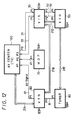
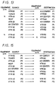
- FIG. 12 shows other embodiment of the AV system from which the VTR 40 is removed. Accordingly, in this case, as shown in FIG. 13, the flag N representing the non-use is set to the VTR 40.
- FIG. 14 shows other embodiment of the AV system from which the tuner 80 is removed. Accordingly, in this case, as shown in FIG. 15, the non-use flag N is set to the tuner 80.
- FIG. 16 shows other embodiment of the AV system from which the MDP 70 is omitted. Accordingly, in this case, as shown in FIG. 17, the non-use flag N is set to the MDP 70.
- FIG. 18 shows other embodiment of the AV system from which the VTR 50 is omitted. Accordingly, in this case, as shown in FIG. 19, the non-use flag N is set to the VTR 50.
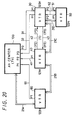
- FIG. 20 shows other embodiment of the AV system from which the MDP 70 and the tuner 80 are omitted. Accordingly, as shown in FIG. 21, the non-use flag N are set to the MDP 70 and the tuner 80.
- FIG. 22 shows other embodiment of the AV system from which the VTR 50 and the tuner 80 are omitted.
- the non-use flag N are set top the VTR 50 and the tuner 80.
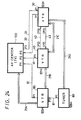
- FIG. 24 shows other embodiment of the AV system from which the VTR 50 and the MDP 70 are omitted.
- the non-use flag is set to the VTR 50 and the MDP 70.
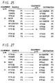
- the VTR 50, the MDP 70 and the tuner 80 are omitted from the AV system. Accordingly, in this case, as shown in FIG. 27, the non-use flag N is set to the three equipments of the VTR 50, the MDP 70 and the tuner 80.
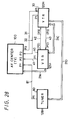
- the VTR 50, the MDP 70 and the VTR 60 are omitted from the AV system. Accordingly, in this case, as shown in FIG. 29, the non-use flag N is set to the VTR 50, the VTR 60 and the MDP 70.
- the VTR 40, the VTR 50 and the tuner 80 are omitted from the AV system. Accordingly, in this case, as shown in FIG. 31, the non-use flag N is set to the VTR 40, the VTR 50 and the tuner 80.
- a flag (path) can be used to determine whether or not the connection line (path) which is described in the standard pattern but is not connected in actual practice is used.
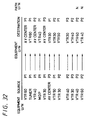
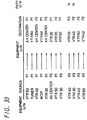
- FIGS. 32 and 33 show such embodiments. With this arrangement, it is possible to reduce prepared data base much more.
- the standard pattern shown in FIG. 4 and the standard pattern shown in FIG. 6 can use a common data base.
- the AV system shown in FIG. 1 if data indicative of all possible connected states are memorized in advance, then it becomes possible to manage a pattern with the same electronic equipments but with different connected states under the common standard pattern.
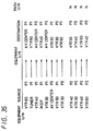
- Data bases of the AV systems shown in FIGS. 4 and 6 are the same configuration as shown in FIGS. 32 and 33. Specifically, all equipments composing the AV system and all possible connected states (connection lines) are described in these data bases. Then, of the described paths, the non-use flag N is set to a path which is not yet connected (used) in actual practice.
- the non-use flag N is set to the path extending from the plug P2 of the VTR 40 to the plug P2 of the VTR 60 and to the path extending from the plug P2 of the VTR 60 to the plug P2 of the VTR 40,
- the patterns are managed under the data base shown in FIG. 33. Specifically, of previously-prepared paths, the non-use flag N is set to the path extending from the plug P2 of the VTR 40 to the plug P3 of the VTR 30 and to the path extending from the plug P3 of the VTR 30 to the plug P2 of the VTR 40.
- the CPU 4 can detect a difference between the path of the standard pattern and the actual path. Therefore, when the respective AV equipments are controlled, it is possible to confirm the fundamental connected state on the basis of the table memorized in the connection configuration information ROM 5A. Further, it is possible to determine on the basis of the path flag memorized in the nonvolatile memory 7 a path which actually exists. Therefore, proper commands can be sent to the respective AV equipments in response to the judged results.
- the non-use flag N is set to the path extending from the plug P2 of the VTR 40 to the plug P3 of the VTR 30, the path extending from the plug P3 of the VTR 30 to the plug P2 of the VTR 40, the path extending from the plug P2 of the VTR 40 to the plug P2 of the VTR 60 and the path extending from the plug P2 of the VTR 60 to the plug P2 of the VTR 40.
- the CPU 4 reads out the presently-selected standard pattern from the standard patterns memorized in the connection configuration information ROM 5A, controls the picture display IC 14 and generates and supplies image data corresponding to the read-out standard pattern to the CRT 13 which then displays an image of the corresponding standard pattern.
- the CRT 13 displays an image corresponding to the standard pattern shown in FIG. 4.
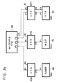
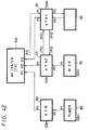
- the CRT 13 displays the standard pattern in the form such that the VTR 60 is not omitted as shown in FIG. 37 but that the VTR 60 is displayed with characters not added in the bloc of the VTR.
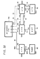
- AV equipments that are connected in actual practice are displayed with characters, such as VTR, AV CENTER, MDP, TUNER or the like added to their blocks. Therefore, the user can easily distinguish the AV equipments that are now actually connected and the AV equipments that are not connected from each other. Thus, when the AV system is expanded, it becomes possible for the user to easily confirm where to add new AV equipments.
- the display shown in FIG. 10 is not carried out but the display shown in FIG. 18 is carried out. Also in this case, one block is displayed at the position to which the VTR 30 should be connected originally.
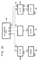
- the display shown in FIG. 14 is not carried out but the display shown in FIG. 40 is carried out.
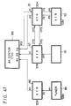
- the display shown in FIG. 16 is not carried out but the display shown in FIG. 41 is carried out.
- the display shown in FIG. 20 is not carried out but the display shown in FIG. 43 is carried out.
- the display shown in FIG. 22 is not carried out but the display shown in FIG. 44 is carried out.
- the display shown in FIG. 26 is not carried out but the display shown in FIG. 45 is carried out.
- the display shown in FIG. 46 is carried out.
- the display shown in FIG. 47 is carried out.
- the display shown in FIG. 48 is carried out.
- the display shown in FIG. 49 is carried out.
- an AV signal line which is made active (now receiving attention) by the feature execution or the like in the AV signal lines can be displayed so as to be distinguished from other signal lines.
- the output of the tuner 80 is supplied to the VTR 60 and the signal output from the VTR 60 is supplied to the plug P1 of the AV center 100, whereby the AV signal lines 81 and 61 are displayed in red.
- the AV signal line can be displayed with thickness and concentration different from those of other AV signal lines. Further, the AV signal line which now receives an attention can be flashed.
- the user can recognize the AV signal line which now receives an attention with ease reliably, thereby making it possible to prevent troubles, such as an erroneous connection or the like.
- VS-2000 can be displayed as names of respective blocks instead of general names such as VTR, MDP, tuner or the like. In this case, there is required a processing in which the user should designate names in advance.
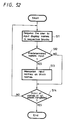
- FIG. 52 is a flowchart showing a processing in which the user designates names.
- step S11 the CPU 4 controls the picture display IC 14 to display a predetermined message on the CRT 13 to thereby request the user to input display names in respective blocks. It is determined in the next decision step S12 whether or not the user input predetermined names. If predetermined names are input as represented by a YES at decision step S12, then the processing proceeds to step S13, whereat input names are supplied to and memorized in the nonvolatile memory 7, for example, as block names. If names are not designated as represented by a NO at decision step S12, then the processing of step S13 is skipped.
- next decision step S14 it is determined in next decision step S14 whether or not the input of names of all blocks is completed. If a NO is output at decision step S14, the above-mentioned steps are repeated until the input of names of all blocks is completed. If the input of names of all blocks is completed as represented by a YES at decision step S14, then the processing is ended.
- step S21 it is determined in decision step S21 whether or not names of respective blocks are memorized. If the names of blocks are memorized as represented by a YES at decision step S21, then the processing proceeds to step S22, whereat names memorized in the non-volatile memory 7 are read out and then displayed as the names of the blocks.
- “S-VHS-100” is displayed as the name in the block of the VTR 40 instead of "VTR”.
- "Hi-8" is displayed instead of "VTR”.
- BS-2000 is displayed instead of "tuner", respectively.
- step S23 If particular names are not memorized as represented by a NO at decision step S23, then the processing proceeds to step S23, whereat general names that are prepared for the blocks in advance are displayed.
- "VTR" are respectively displayed and "MDP” is displayed in the block of the MDP 70.
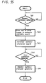
- the AV center 100 can confirm the connected states of the respective AV equipments as follows. In this case, the AV center 100 implements the processing shown in a flowchart of FIG. 54 and the respective AV equipments (e.g., MDP 70) implements the processing shown in a flowchart of FIG. 55.
- the respective AV equipments e.g., MDP 70
- the MDP 70 further includes a CPU 70D for controlling the whole operation of the MDP 70.
- the MDP 70 includes, in addition to fundamental devices for reproducing a video or compact disc to output video and audio data, an LED 70A or a buzzer 70B for generating a predetermined alarm and a generator 70C for generating a symbol signal or a character signal.
- step S31 the CPU 4 outputs a present command to the MDP 70 (address is 130H). Having received the present command from the CPU 4, the MDP 70 executes the processing shown in a flowchart of FIG. 54.
- the MDP 70 is set in the standby mode until it receives the present command generated from the CPU 4 in step S31. If it is determined in decision step whether or not the present command is detected. If a present command is detected as represented by a YES at decision step S41, then the processing proceeds to step S42, whereat the CPU 70D of the MDP 70 causes the LED 70A to blink or drives the buzzer 70B to emanate a predetermined alarming sound. Thus, it is possible for the user to confirm that the signal path confirmation command is input to the MDP 70 from the AV center 100.
- the CPU 70D drives the generator 70C to generated a symbol or character (e.g., MDP) signal so that the user can recognize the MDP 70.
- a symbol or character e.g., MDP
- This data is supplied through the AV signal line 71 to the VTR 40, and further supplied from the VTR 40 through the AV signal line 41 to the CRT 13 from the plug P2 of the AV center 100 through the selector 18, thereby being displayed on the picture screen of the CRT 13.
- the character, "MDP" is displayed on the picture screen of the CRT 13. Consequently, the user can confirm that the AV signal line is correctly connected such that the output signal of the MDP 70 can correctly be supplied to the AV center 100.
- the CPU 4 of the AV center 100 outputs the present command at step S31 shown in FIG. 54 and proceeds to step S32, whereat the CPU 4 issues a connection command to the VTR 40 to maintain the internal AV signal line so that the signal output from the MDP 70 is supplied to the AV center 100.
- the VTR 40 effects the internal connection in response to the connection command supplied thereto so that the video signal (signal in which the character MDP is superimposed on the OSD superimposed on the video signal) output from the MDP 70 is output to and displayed by the CRT 13 of the AV center 100.
- the signal output from the MDP 70 is converted into a signal that can be detected by the CPU 4, then it is possible for the CPU 4 to automatically detect such signal.
- the processing proceeds to the next step S34, whereat the CPU 4 issues a connection confirmation end command to the MDP 70.
- the MDP 70 generates the video signal in step S43 shown in FIG. 55, and proceeds to the next decision step S44, wherein the MDP 70 is set in the standby mode until the end command is supplied thereto from the CPU 4 of the AV center 100. If the end command is detected as represented by a YES at decision step S44, then the processing proceeds to step S45, whereat the symbol/character generator is disabled. Then, the processing is ended.
- the video signal can be displayed in PIP or P-OUT-P in the AV center 100.
- the AV system control method of the present invention since information indicating whether or not the AV equipment included in the standard pattern is used in the AV system in actual practice is memorized and the respective AV equipments are controlled in accordance with such use information, it becomes possible to reduce the number of previously-prepared standard patterns. As a consequence, the memory capacity can be reduced and the AV system can be made inexpensive.
- the AV system control method of the present invention since information indicating whether or not the connected states of the AV equipments included in the standard pattern are realized in actual practice is memorized and the respective AV equipments are controlled in response to the information representing the connected states, it becomes possible to manage many connected states by less standard patterns.
- the AV system control method of the present invention since the AV equipments that are used in actual practice and the AV equipments that not used in actual practice can be displayed so as to be discriminated when the standard pattern is displayed, it becomes possible to confirm the system arrangement with ease. Therefore, when new AV equipments are added to the AV system, the AV system can cope with such new added AV equipments rapidly.
- the user can be prevented from mistaking the AV equipment from a plurality of AV equipments with the same function.
- connection line of connection lines of the AV equipments forming the standard pattern can be discriminated from other connection lines, the connected states can be recognized rapidly and reliably. Thus, it becomes possible to avoid an erroneous connection.
- the AV system control method of the present invention since an output corresponding to a signal input between the first and second AV equipments is generated, it becomes possible to reliably confirm the connected states.
Landscapes
- Engineering & Computer Science (AREA)
- Multimedia (AREA)
- Signal Processing (AREA)
- General Engineering & Computer Science (AREA)
- Computer Networks & Wireless Communication (AREA)
- Television Signal Processing For Recording (AREA)
- Selective Calling Equipment (AREA)
Applications Claiming Priority (3)
| Application Number | Priority Date | Filing Date | Title |
|---|---|---|---|
| JP188559/93 | 1993-07-30 | ||
| JP18855993 | 1993-07-30 | ||
| JP18855993 | 1993-07-30 |
Publications (2)
| Publication Number | Publication Date |
|---|---|
| EP0637140A2 true EP0637140A2 (de) | 1995-02-01 |
| EP0637140A3 EP0637140A3 (de) | 2000-01-12 |
Family
ID=16225813
Family Applications (1)
| Application Number | Title | Priority Date | Filing Date |
|---|---|---|---|
| EP94305514A Withdrawn EP0637140A3 (de) | 1993-07-30 | 1994-07-26 | Konfigurationsverfahren für ein Audio-Video-Gerät mit digitaler Busschnittstelle |
Country Status (2)
| Country | Link |
|---|---|
| US (1) | US5598278A (de) |
| EP (1) | EP0637140A3 (de) |
Cited By (1)
| Publication number | Priority date | Publication date | Assignee | Title |
|---|---|---|---|---|
| WO1999006916A3 (en) * | 1997-07-29 | 1999-04-22 | Koninkl Philips Electronics Nv | Data bus device having means for the allocation of information after a bus reset |
Families Citing this family (26)
| Publication number | Priority date | Publication date | Assignee | Title |
|---|---|---|---|---|
| US5884040A (en) * | 1995-01-11 | 1999-03-16 | Sony Corporation | Per-packet jamming in a multi-port bridge for a local area network |
| US5940597A (en) * | 1995-01-11 | 1999-08-17 | Sony Corporation | Method and apparatus for periodically updating entries in a content addressable memory |
| US6256313B1 (en) | 1995-01-11 | 2001-07-03 | Sony Corporation | Triplet architecture in a multi-port bridge for a local area network |
| US5857075A (en) * | 1995-01-11 | 1999-01-05 | Sony Corporation | Method and integrated circuit for high-bandwidth network server interfacing to a local area network |
| JP3867313B2 (ja) * | 1996-03-29 | 2007-01-10 | ソニー株式会社 | Avデータ処理制御装置およびその方法 |
| US6157951A (en) * | 1997-09-17 | 2000-12-05 | Sony Corporation | Dual priority chains for data-communication ports in a multi-port bridge for a local area network |
| US6363067B1 (en) | 1997-09-17 | 2002-03-26 | Sony Corporation | Staged partitioned communication bus for a multi-port bridge for a local area network |
| US6301256B1 (en) | 1997-09-17 | 2001-10-09 | Sony Corporation | Selection technique for preventing a source port from becoming a destination port in a multi-port bridge for a local area network |
| US6308218B1 (en) | 1997-09-17 | 2001-10-23 | Sony Corporation | Address look-up mechanism in a multi-port bridge for a local area network |
| US6617879B1 (en) | 1997-09-17 | 2003-09-09 | Sony Corporation | Transparently partitioned communication bus for multi-port bridge for a local area network |
| US6744728B1 (en) | 1997-09-17 | 2004-06-01 | Sony Corporation & Sony Electronics, Inc. | Data pipeline timing optimization technique in a multi-port bridge for a local area network |
| US6442168B1 (en) | 1997-09-17 | 2002-08-27 | Sony Corporation | High speed bus structure in a multi-port bridge for a local area network |
| DE19757239B4 (de) * | 1997-12-22 | 2010-11-11 | Deutsche Thomson-Brandt Gmbh | Einheitliche Menüführung von Geräten der Unterhaltungselektronik |
| DE69937919T9 (de) * | 1998-02-25 | 2009-04-30 | Nec Corp. | Netz mit einem Netzverwaltungssystem, zur Verbindung mehrerer Vorrichtungen zur Speicherung und Wiedergabe von Fernsehprogrammen |
| US20010026533A1 (en) * | 1998-07-06 | 2001-10-04 | Andreas Schwager | Method to perform a scheduled action of network devices |
| JP2000307594A (ja) * | 1999-04-21 | 2000-11-02 | Nec Corp | Av機器の機能の最適処理分散システム |
| DE10145708B4 (de) * | 2000-09-19 | 2007-02-01 | Samsung Electronics Co., Ltd., Suwon | Vorrichtung und Verfahren zum Verbinden eines Basismoduls mit einem Funktionserweiterungsmodul in einem AV-System |
| US20030064691A1 (en) * | 2001-10-01 | 2003-04-03 | Join Computer Co., Ltd. | Automatic radio frequency signal switching circuit |
| WO2007123001A1 (ja) * | 2006-04-17 | 2007-11-01 | Panasonic Corporation | Avシステム |
| US8910265B2 (en) | 2012-09-28 | 2014-12-09 | Sonos, Inc. | Assisted registration of audio sources |
| US9319409B2 (en) | 2013-02-14 | 2016-04-19 | Sonos, Inc. | Automatic configuration of household playback devices |
| US9237384B2 (en) | 2013-02-14 | 2016-01-12 | Sonos, Inc. | Automatic configuration of household playback devices |
| US9933920B2 (en) | 2013-09-27 | 2018-04-03 | Sonos, Inc. | Multi-household support |
| US9720576B2 (en) | 2013-09-30 | 2017-08-01 | Sonos, Inc. | Controlling and displaying zones in a multi-zone system |
| US9241355B2 (en) | 2013-09-30 | 2016-01-19 | Sonos, Inc. | Media system access via cellular network |
| US10028028B2 (en) | 2013-09-30 | 2018-07-17 | Sonos, Inc. | Accessing last-browsed information in a media playback system |
Family Cites Families (10)
| Publication number | Priority date | Publication date | Assignee | Title |
|---|---|---|---|---|
| US4484261A (en) * | 1981-01-19 | 1984-11-20 | Texas Instruments Incorporated | Data processing system having interlinked fast and slow memory means and interlinked program counters |
| US5463619A (en) * | 1987-08-17 | 1995-10-31 | U.S. Philips Corporation | Local communication bus system comprising a set of interconnected devices, a control bus, and a set of signal interconnections, and a device and a switchbox for use in such system |
| US4837627A (en) * | 1987-08-19 | 1989-06-06 | Rca Licensing Corporation | Programmable operating-parameter control appatatus for a television receiver |
| US4989081A (en) * | 1988-11-14 | 1991-01-29 | Sony Corporation | Home-bus-information system |
| JP2751270B2 (ja) * | 1988-11-29 | 1998-05-18 | 松下電器産業株式会社 | Avtcシステム |
| EP0432316A1 (de) * | 1989-12-14 | 1991-06-19 | Koninklijke Philips Electronics N.V. | Lokales Kommunikationsbussystem mit einer Anzahl miteinander verbundener Einrichtungen, einem Steuerbus und einer Anzahl von Signalverbindungen sowie einer Einrichtung und einem Schaltkasten zur Verwendung in einem derartigen System |
| US5170252A (en) * | 1990-04-09 | 1992-12-08 | Interactive Media Technologies, Inc. | System and method for interconnecting and mixing multiple audio and video data streams associated with multiple media devices |
| DE69203525T3 (de) * | 1991-04-26 | 2002-08-08 | Pioneer Electronic Corp., Tokio/Tokyo | Datenübertragungssystem in einem Fahrzeug. |
| KR940016216A (ko) * | 1992-12-28 | 1994-07-22 | 오오가 노리오 | 오디오/비디오시스템 및 접속설정방법 |
| US5475835A (en) * | 1993-03-02 | 1995-12-12 | Research Design & Marketing Inc. | Audio-visual inventory and play-back control system |
-
1994
- 1994-07-22 US US08/278,954 patent/US5598278A/en not_active Expired - Lifetime
- 1994-07-26 EP EP94305514A patent/EP0637140A3/de not_active Withdrawn
Cited By (1)
| Publication number | Priority date | Publication date | Assignee | Title |
|---|---|---|---|---|
| WO1999006916A3 (en) * | 1997-07-29 | 1999-04-22 | Koninkl Philips Electronics Nv | Data bus device having means for the allocation of information after a bus reset |
Also Published As
| Publication number | Publication date |
|---|---|
| US5598278A (en) | 1997-01-28 |
| EP0637140A3 (de) | 2000-01-12 |
Similar Documents
| Publication | Publication Date | Title |
|---|---|---|
| US5598278A (en) | System configuration method for audio-video apparatus with digital bus interface | |
| US5621659A (en) | Central control device and operation devices | |
| US5815631A (en) | Apparatus and method for controlling an audio video systems | |
| KR100391405B1 (ko) | 입력기기선택방법 | |
| EP0658048B1 (de) | Verfahren zur verbindung von audiovisuellen geräten mit einem audiovisuellen system | |
| EP0604166B1 (de) | Übertragungssystem und Übertragungsvorrichtungen mit Verriegelungsfunktion | |
| US5204662A (en) | Monitor television apparatus | |
| US5917557A (en) | Audio/video system selector | |
| US5802300A (en) | Audio video system | |
| US6604235B1 (en) | Operating system upgrading | |
| US5448562A (en) | Bi-directional bus system and transmitting, receiving, and communication methods for same | |
| EP0371719A2 (de) | Gerätebedienungssystem mit Bildschirmanzeige | |
| EP0608624B1 (de) | Hierarchisches Leitsystem für audiovisuelle Apparatur und Verfahren zum Bilden eines solchen Systems | |
| US6020928A (en) | Image processing apparatus and method for reproducing and recording therein | |
| JPH05161084A (ja) | 入出力状態表示装置 | |
| EP0608048B1 (de) | Vorrichtung und Verfahren zur Auswahl von Signalleitungen zur Verbindung mit einer Mehrzahl von Audio-Videogeräten | |
| JP3934675B2 (ja) | ローカルコミュニケーションシステム及びこのシステムの使用のためのステーション | |
| JPH07336724A (ja) | ビデオ内蔵型テレビジョン受像機 | |
| JP3270882B2 (ja) | Avシステム制御方法 | |
| JPH0636529Y2 (ja) | Avシステム | |
| US7437056B2 (en) | Combination system and copy error preventing method thereof | |
| EP1355307B1 (de) | Monitor | |
| JP2959113B2 (ja) | モニタ・テレビジョン装置 | |
| JP2676874B2 (ja) | モニタ・テレビジョン装置 | |
| JPH05252459A (ja) | テレビジョン受像機 |
Legal Events
| Date | Code | Title | Description |
|---|---|---|---|
| PUAI | Public reference made under article 153(3) epc to a published international application that has entered the european phase |
Free format text: ORIGINAL CODE: 0009012 |
|
| AK | Designated contracting states |
Kind code of ref document: A2 Designated state(s): DE FR GB NL |
|
| PUAL | Search report despatched |
Free format text: ORIGINAL CODE: 0009013 |
|
| AK | Designated contracting states |
Kind code of ref document: A3 Designated state(s): DE FR GB NL |
|
| 17P | Request for examination filed |
Effective date: 20000613 |
|
| 17Q | First examination report despatched |
Effective date: 20011129 |
|
| STAA | Information on the status of an ep patent application or granted ep patent |
Free format text: STATUS: THE APPLICATION IS DEEMED TO BE WITHDRAWN |
|
| 18D | Application deemed to be withdrawn |
Effective date: 20021219 |