EP0637168A1 - Dispositif de contrôle d'un appareil d'entrée d'images - Google Patents
Dispositif de contrôle d'un appareil d'entrée d'images Download PDFInfo
- Publication number
- EP0637168A1 EP0637168A1 EP94111621A EP94111621A EP0637168A1 EP 0637168 A1 EP0637168 A1 EP 0637168A1 EP 94111621 A EP94111621 A EP 94111621A EP 94111621 A EP94111621 A EP 94111621A EP 0637168 A1 EP0637168 A1 EP 0637168A1
- Authority
- EP
- European Patent Office
- Prior art keywords
- display screen
- image input
- input apparatus
- optical system
- camera
- Prior art date
- Legal status (The legal status is an assumption and is not a legal conclusion. Google has not performed a legal analysis and makes no representation as to the accuracy of the status listed.)
- Granted
Links
- 230000003287 optical effect Effects 0.000 claims abstract description 38
- 238000000034 method Methods 0.000 description 5
- 238000010586 diagram Methods 0.000 description 4
- 238000004091 panning Methods 0.000 description 2
- 230000005540 biological transmission Effects 0.000 description 1
- 238000006243 chemical reaction Methods 0.000 description 1
- 230000000694 effects Effects 0.000 description 1
- 230000006870 function Effects 0.000 description 1
- 239000004973 liquid crystal related substance Substances 0.000 description 1
- 230000000007 visual effect Effects 0.000 description 1
Images


Classifications
-
- H—ELECTRICITY
- H04—ELECTRIC COMMUNICATION TECHNIQUE
- H04N—PICTORIAL COMMUNICATION, e.g. TELEVISION
- H04N7/00—Television systems
- H04N7/18—Closed-circuit television [CCTV] systems, i.e. systems in which the video signal is not broadcast
- H04N7/183—Closed-circuit television [CCTV] systems, i.e. systems in which the video signal is not broadcast for receiving images from a single remote source
-
- H—ELECTRICITY
- H04—ELECTRIC COMMUNICATION TECHNIQUE
- H04N—PICTORIAL COMMUNICATION, e.g. TELEVISION
- H04N23/00—Cameras or camera modules comprising electronic image sensors; Control thereof
- H04N23/60—Control of cameras or camera modules
- H04N23/63—Control of cameras or camera modules by using electronic viewfinders
- H04N23/631—Graphical user interfaces [GUI] specially adapted for controlling image capture or setting capture parameters
- H04N23/632—Graphical user interfaces [GUI] specially adapted for controlling image capture or setting capture parameters for displaying or modifying preview images prior to image capturing, e.g. variety of image resolutions or capturing parameters
-
- H—ELECTRICITY
- H04—ELECTRIC COMMUNICATION TECHNIQUE
- H04N—PICTORIAL COMMUNICATION, e.g. TELEVISION
- H04N23/00—Cameras or camera modules comprising electronic image sensors; Control thereof
- H04N23/60—Control of cameras or camera modules
- H04N23/66—Remote control of cameras or camera parts, e.g. by remote control devices
- H04N23/661—Transmitting camera control signals through networks, e.g. control via the Internet
-
- H—ELECTRICITY
- H04—ELECTRIC COMMUNICATION TECHNIQUE
- H04N—PICTORIAL COMMUNICATION, e.g. TELEVISION
- H04N23/00—Cameras or camera modules comprising electronic image sensors; Control thereof
- H04N23/60—Control of cameras or camera modules
- H04N23/695—Control of camera direction for changing a field of view, e.g. pan, tilt or based on tracking of objects
Definitions
- This invention relates to a control device for an image input apparatus and, more specifically, to a control device which is suitable for remotely operating a camera as in the case of a video conference system.
- a control device for an image input apparatus which is equipped with an optical system having a magnification varying lens
- the control device comprising display means for displaying input images, input means which enables an arbitrary position on a display screen of the display means to be designated; calculation means for calculating the distance between a predetermined position on the display screen and the arbitrary position on the basis of zooming information of the optical system, and control means for controlling the image input apparatus in accordance with calculation results obtained by the calculation means.
- Fig. 1 is a schematic block diagram showing an embodiment of the present invention as applied to a terminal in a video conference system.
- Numeral 10 indicates a camera for photographing a user of the system;
- numeral 12 indicates a photographing zoom lens unit;
- numeral 14 indicates a zoom control circuit for moving a zooming lens 12a of the lens unit 12 in the direction of the optical axis;
- numeral 16 indicates a focus control circuit for moving a focusing lens 12b of the lens unit 12 in the direction of the optical axis;
- numeral 20 indicates an image sensor which converts optical images obtained by the lens unit 12 and an aperture 18 to electric signals; and
- numeral 22 indicates a camera signal processing circuit for converting the electric signals obtained by the image sensor 20 to video signals.
- Numeral 24 indicates a pan control circuit which is on a pan head 23 and which moves the photographic optical axis of the camera 10 to the right and left;
- numeral 26 indicates a tilt control circuit which is on the panhead 23 and which moves the photographic optical axis of the camera 10 up and down; and
- numeral 28 indicates a camera control circuit for controlling the camera 10 as a whole.
- Numeral 30 indicates a computer constructed in the same way as ordinary computers; numeral 32 indicates a CPU for overall control; numeral 34 indicates a ROM; numeral 36 indicates a RAM; numeral 38 indicates a video interface to which output video signals from the camera 10 are input; and numeral 40 indicates a communications interface which transmits and receives data and control signals to and from an external communications network and transmits and receives control signals to and from the camera 10.
- Numeral 42 indicates a coordinate input device consisting of a digitizer, a mouse or the like; numeral 44 indicates an interface for the coordinate input device 42; numeral 46 indicates a video memory (VRAM); and numeral 48 indicates a display control device for controlling the image display of a monitor 50 consisting of a CRT, a liquid crystal display or the like.
- VRAM video memory
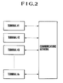
- a number of terminals as shown in Fig. 1 are connected to each other through the intermediation of a communications network.
- This embodiment functions in a particularly effective manner when applied to a case where it is used to remotely control a camera at an image transmission end terminal from an image reception end terminal in a video conference which is being executed between terminals.
- the operation of this embodiment will be explained with reference to a case where the camera 10 is operated within the system shown in Fig. 1.
- the features of this embodiment as utilized in the above two cases are the same except for the fact that the processes of image coding and decoding are omitted in the latter case.
- a photographic image obtained by the camera 10 is written to the memory 46 through the video interface 38.
- the display control circuit 48 successively reads image data stored in the video memory 46, whereby the monitor 50 is controlled to display the image.
- the user designates an arbitrary position (x, y), which he or she intends to be the center, through the coordinate input device 42 (S1).
- the CPU 32 calculates the disparity ( ⁇ X, ⁇ Y) between the designated position (x, y) and the coordinates (a, b) of the center of the photographic image displayed on the screen (when no window display system is adopted, it is the center of the screen of the monitor 50 and, when a window display system is adopted, it is the center of the display window of the photographic image) (S2).
- a movement command e.g., a command Mov ( ⁇ X, ⁇ Y)
- the camera control circuit 28 Upon receiving this movement command (S4), the camera control circuit 28 first obtains zooming position information of the zooming lens 12a from the zoom control circuit 14 (S5), and determines the conversion factor k of the amount of movement from the zooming position information thus obtained (S6). That is, the photographic image is displayed in a size corresponding to the variable magnification of the lens unit 12. For example, as shown in Fig. 4, distances which appear the same when displayed on the screen of the monitor 50 are different from each other in the actual field depending upon the magnification, i.e., the angle of view. In view of this, it is necessary to convert a distance on the monitor screen to an amount of movement corresponding to the angle of view (the pan angle and the tilt angle). For this purpose, the camera control circuit 28 is equipped with a conversion table for determining the conversion factor k.
- the camera control circuit 28 determines the pan and tilt angles of rotation in accordance with the actual amount of movement ( ⁇ Xr, ⁇ Yr) (S8) to control the pan control circuit 24 and the tilt control circuit 26, thereby pointing the photographic optical axis of the camera 10 in the designated direction (S9).
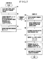
- Fig. 3 shows a flowchart for the latter case which differs from the above-described case in that the zooming position information of the zooming lens 12a is transferred from the camera 10 to the computer 30, which calculates the pan and tilt angles of movement and transfers them to the camera 10.
- the user designates an arbitrary position (x, y), which he or she intends to be the center of the photographic image displayed on the monitor 50, by using the coordinate input device 42 (S11).
- the CPU 32 calculates the disparity ( ⁇ X, ⁇ Y) between the designated position (x, y) and the coordinates (a, b) of the center of the photographic image as displayed on the screen (when no window display system is adopted, it is the center of the screen of the monitor 50 and, when a window display system is adopted, it is the center of the display window of the photographic image) (S12). Then, the CPU 32 requires the camera 10 to provide zooming position information (S13).
- the camera control circuit 28 of the camera 10 Upon the request of zooming position information from the computer 30, the camera control circuit 28 of the camera 10 obtains zooming position information from the zoom control circuit 14 (S14), and transfers it to the computer 30 (S15).
- the CPU 32 determines the conversion factor k from the zooming position information from the camera 10 (S16, S17).
- the CPU 32 is equipped with a conversion factor table for converting a distance on the screen of the monitor 50 to an amount of movement corresponding to the angles of view (the pan and tilt angles), and determines the conversion factor k.
- the CPU 32 multiplies the determined conversion factor k by the previously calculated ⁇ X and ⁇ Y to calculate the actual amount of movement ( ⁇ Xr, ⁇ Yr) (S18), and determines the pan and tilt angles of rotation corresponding to the calculated actual amount of movement ( ⁇ Xr, ⁇ Yr), transmitting a movement command of that angle of rotation to the camera 10 (S20).
- the camera control circuit 28 of the camera 10 receives the movement command from the computer 30 (S21), and controls the pan control circuit 24 and the tilt control circuit 26 in accordance with the command to point the photographic optical axis of the camera 10 in the designated direction (S22).
- a photographic range is designated by two points on the screen of the monitor 50
- the user designates two points (x1, y1) and (x2, y2) in the photographic image plane, which is displayed on the monitor 50, by the coordinate input device 42 (S31).
- the CPU 32 calculates a middle point (x0, y0) thereof from the designated two points (x1, y1) and (x2, y2) (S32).
- the CPU32 calculates the difference ( ⁇ X, ⁇ Y) between the middle point (x0, y0) and the coordinates (a, b) of the center of the photographic-image displaying portion of the monitor 50 (when no window display system is adopted, it is the center of the entire screen of the monitor 50, and when a window display system is adopted, it is the center of the photographic image display window) (S33).
- the camera control circuit 28 of the camera 10 receives this command thus transferred (S36), and obtains zooming position information of the zooming lens 12a from the zoom control circuit 14 (S37), determining the conversion factor k of the pan and tilt amounts of movement from the zooming position information thus obtained (S38).
- the camera control circuit 28 calculates the actual amounts of movement corresponding to the actual amount of movement ( ⁇ Xr, ⁇ Yr) calculated in step S39, and calculates the amount of zooming movement corresponding to the amount of movement ⁇ z calculated in step S40 (S41). In then controls the pan control circuit 24, the tilt control circuit 26 and the zoom control circuit 14, pointing the photographic optical axis of the camera 10 in the designated direction and changing the magnification of the lens unit 12 (S42).
- the above-described embodiment is not effective when the user wishes to observe ranges other than that displayed on the monitor screen.
- the user has to move the zooming lens 12a of the camera 10 to wide-angle end through another operation, and then perform the above operation.
- These procedures could be simplified by the following procedures: the CPU sets imaginary screens above and below, and on the right and left-hand sides, of the display screen displaying an image that is being photographed. These imaginary screens may be adjacent to, or partly overlap, or spaced apart from, the actual display screen.
- Fig. 7 shows the flowchart of an operation utilizing such imaginary screens.
- the user selects one of the imaginary screens by the coordinate input device 42 or the like (S51).
- the camera control circuit 28 which receives this movement command (S54), first obtains the zooming position information of the zooming lens 12a from the zoom control circuit 14 (S55), and then determines the conversion factor k of the amount of movement from the obtained zooming position information, as in the abvoe-described case (S56).
- the present invention is obviously also applicable to a case where a camera at an image-transmission-end terminal is to be remotely controlled from an image-reception-end terminal in a video conference or the like.
- this embodiment a visual and intuitive camera operation can be realized, thereby attaining an improvement in operability.
- this embodiment proves markedly effective in cases where remote control is to be performed.
- a control device for an image input apparatus which is equipped with an optical system having a magnification varying lens, includes a monitor for displaying input images, an input device which enables an arbitrary position on a display screen of the monitor to be designated, a calculation device for calculating the distance between a predetermined position on the display screen and the arbitrary position on the basis of zooming information of the optical system, and a controller for controlling the image input apparatus in accordance with the calculation results obtained by the calculation device.
Landscapes
- Engineering & Computer Science (AREA)
- Multimedia (AREA)
- Signal Processing (AREA)
- Human Computer Interaction (AREA)
- Two-Way Televisions, Distribution Of Moving Picture Or The Like (AREA)
- Studio Devices (AREA)
Applications Claiming Priority (2)
| Application Number | Priority Date | Filing Date | Title |
|---|---|---|---|
| JP185366/93 | 1993-07-27 | ||
| JP18536693A JP3431953B2 (ja) | 1993-07-27 | 1993-07-27 | カメラ制御装置及び方法 |
Publications (2)
| Publication Number | Publication Date |
|---|---|
| EP0637168A1 true EP0637168A1 (fr) | 1995-02-01 |
| EP0637168B1 EP0637168B1 (fr) | 1999-04-28 |
Family
ID=16169549
Family Applications (1)
| Application Number | Title | Priority Date | Filing Date |
|---|---|---|---|
| EP94111621A Expired - Lifetime EP0637168B1 (fr) | 1993-07-27 | 1994-07-26 | Dispositif et procédé de contrÔle d'un appareil d'entrée d'images |
Country Status (3)
| Country | Link |
|---|---|
| EP (1) | EP0637168B1 (fr) |
| JP (1) | JP3431953B2 (fr) |
| DE (1) | DE69418111T2 (fr) |
Cited By (8)
| Publication number | Priority date | Publication date | Assignee | Title |
|---|---|---|---|---|
| EP0735745A3 (fr) * | 1995-03-31 | 1997-12-10 | Canon Kabushiki Kaisha | Méthode et appareil de traitement d'information visuelle |
| EP0776130A3 (fr) * | 1995-11-27 | 1998-03-04 | Canon Kabushiki Kaisha | Système de contrÔle de caméra avec fréquence de trame variable |
| EP0908053A4 (fr) * | 1996-06-24 | 2000-03-29 | Behere Corp | Appareil de prise de vues panoramique |
| FR2787668A1 (fr) * | 1998-12-18 | 2000-06-23 | Thomson Csf | Systeme de couplage d'une camera-video a un ordinateur |
| WO2002013513A1 (fr) * | 2000-08-03 | 2002-02-14 | Koninklijke Philips Electronics N.V. | Procede et appareil de calibration d'une camera via une interface graphique |
| WO2002104033A1 (fr) * | 2001-06-13 | 2002-12-27 | Usc Co., Limited | Systeme de reconnaissance video a distance |
| US6707947B1 (en) | 1999-09-22 | 2004-03-16 | Matsushita Electric Industrial Co., Ltd. | Frame switcher and method of switching, digital camera, and monitoring system |
| EP1465413A3 (fr) * | 1995-03-20 | 2010-01-06 | Canon Kabushiki Kaisha | Système de contrôle de caméra |
Families Citing this family (5)
| Publication number | Priority date | Publication date | Assignee | Title |
|---|---|---|---|---|
| US6768563B1 (en) | 1995-02-24 | 2004-07-27 | Canon Kabushiki Kaisha | Image input system |
| JP4628350B2 (ja) * | 2006-12-25 | 2011-02-09 | 株式会社タムロン | カメラ制御装置、カメラ制御方法およびカメラ制御プログラム |
| KR101361800B1 (ko) * | 2008-11-20 | 2014-02-11 | 삼성테크윈 주식회사 | 감시 카메라의 제어 방법 및 이를 사용한 제어 장치 |
| US10070043B2 (en) | 2012-08-15 | 2018-09-04 | Nec Corporation | Image processing system, image processing method, and program |
| WO2025216324A1 (fr) * | 2024-04-12 | 2025-10-16 | 株式会社ニコン | Dispositif de commande, système de commande de photographie, procédé de commande, et programme de commande |
Citations (4)
| Publication number | Priority date | Publication date | Assignee | Title |
|---|---|---|---|---|
| US4720805A (en) * | 1985-12-10 | 1988-01-19 | Vye Scott R | Computerized control system for the pan and tilt functions of a motorized camera head |
| GB2215568A (en) * | 1988-02-22 | 1989-09-20 | Photo Scan Limited | CCTV/surveillance system |
| US4945417A (en) * | 1987-11-16 | 1990-07-31 | Elbex Video, Ltd | Method and apparatus for remotely pre-setting closed circuit television camera |
| WO1991002287A1 (fr) * | 1989-08-09 | 1991-02-21 | Blackshear David M | Systeme de surveillance par camera |
-
1993
- 1993-07-27 JP JP18536693A patent/JP3431953B2/ja not_active Expired - Fee Related
-
1994
- 1994-07-26 DE DE69418111T patent/DE69418111T2/de not_active Expired - Lifetime
- 1994-07-26 EP EP94111621A patent/EP0637168B1/fr not_active Expired - Lifetime
Patent Citations (4)
| Publication number | Priority date | Publication date | Assignee | Title |
|---|---|---|---|---|
| US4720805A (en) * | 1985-12-10 | 1988-01-19 | Vye Scott R | Computerized control system for the pan and tilt functions of a motorized camera head |
| US4945417A (en) * | 1987-11-16 | 1990-07-31 | Elbex Video, Ltd | Method and apparatus for remotely pre-setting closed circuit television camera |
| GB2215568A (en) * | 1988-02-22 | 1989-09-20 | Photo Scan Limited | CCTV/surveillance system |
| WO1991002287A1 (fr) * | 1989-08-09 | 1991-02-21 | Blackshear David M | Systeme de surveillance par camera |
Cited By (10)
| Publication number | Priority date | Publication date | Assignee | Title |
|---|---|---|---|---|
| EP1465413A3 (fr) * | 1995-03-20 | 2010-01-06 | Canon Kabushiki Kaisha | Système de contrôle de caméra |
| EP0735745A3 (fr) * | 1995-03-31 | 1997-12-10 | Canon Kabushiki Kaisha | Méthode et appareil de traitement d'information visuelle |
| US6493031B1 (en) | 1995-03-31 | 2002-12-10 | Canon Kabushiki Kaisha | Visual information processing method and apparatus for extracting feature quantities from a two-dimensional image signal |
| EP0776130A3 (fr) * | 1995-11-27 | 1998-03-04 | Canon Kabushiki Kaisha | Système de contrÔle de caméra avec fréquence de trame variable |
| EP0908053A4 (fr) * | 1996-06-24 | 2000-03-29 | Behere Corp | Appareil de prise de vues panoramique |
| FR2787668A1 (fr) * | 1998-12-18 | 2000-06-23 | Thomson Csf | Systeme de couplage d'une camera-video a un ordinateur |
| US6707947B1 (en) | 1999-09-22 | 2004-03-16 | Matsushita Electric Industrial Co., Ltd. | Frame switcher and method of switching, digital camera, and monitoring system |
| EP1087620A3 (fr) * | 1999-09-22 | 2004-05-12 | Matsushita Electric Industrial Co., Ltd. | Commutateur et méthode de commutation de trames vidéo, caméra numérique, et système de supervision |
| WO2002013513A1 (fr) * | 2000-08-03 | 2002-02-14 | Koninklijke Philips Electronics N.V. | Procede et appareil de calibration d'une camera via une interface graphique |
| WO2002104033A1 (fr) * | 2001-06-13 | 2002-12-27 | Usc Co., Limited | Systeme de reconnaissance video a distance |
Also Published As
| Publication number | Publication date |
|---|---|
| JP3431953B2 (ja) | 2003-07-28 |
| EP0637168B1 (fr) | 1999-04-28 |
| DE69418111D1 (de) | 1999-06-02 |
| DE69418111T2 (de) | 1999-12-23 |
| JPH0746566A (ja) | 1995-02-14 |
Similar Documents
| Publication | Publication Date | Title |
|---|---|---|
| US6677990B1 (en) | Control device for image input apparatus | |
| US7256822B2 (en) | Video system | |
| US9210328B2 (en) | Controller for photographing apparatus and photographing system | |
| US6760063B1 (en) | Camera control apparatus and method | |
| US6445411B1 (en) | Camera control system having anti-blur facility | |
| US7551200B2 (en) | Camera controller and zoom ratio control method for the camera controller | |
| EP0637168A1 (fr) | Dispositif de contrôle d'un appareil d'entrée d'images | |
| JP2016100636A (ja) | 撮像装置 | |
| US20040036792A1 (en) | Camera system and focus information display apparatus | |
| JPH10164420A (ja) | カメラ制御システム及びその装置 | |
| JPH09116886A (ja) | 画像情報通信装置 | |
| CN113840084A (zh) | 一种基于球机ptz回传技术实现全景云台操控的方法 | |
| EP3826289B1 (fr) | Procédé de capture d'image et dispositif de capture d'image | |
| JP3149046B2 (ja) | カメラ停止位置補正制御方式 | |
| US11516404B2 (en) | Control apparatus and control method | |
| KR19980080383A (ko) | 촬상 장치용 컨트롤러 및 촬상 시스템 | |
| JP2981408B2 (ja) | カメラ画像内の目的とする被写体の高速導入制御方法および装置 | |
| JP4332580B2 (ja) | 制御装置および制御方法、並びに監視システム | |
| US20190158751A1 (en) | Display control device and display control system | |
| JP7757254B2 (ja) | 撮像制御装置、撮像装置、映像配信システムおよび撮像制御方法 | |
| JP7844131B2 (ja) | 撮像装置の制御装置、方法及びプログラム | |
| JPH08237590A (ja) | 映像処理装置 | |
| JPH07274150A (ja) | 遠隔カメラ操作機能を有するテレビ会議装置 | |
| JPH1153160A (ja) | 情報表示方法 | |
| JP2025082988A (ja) | 制御装置、制御方法、及びプログラム |
Legal Events
| Date | Code | Title | Description |
|---|---|---|---|
| PUAI | Public reference made under article 153(3) epc to a published international application that has entered the european phase |
Free format text: ORIGINAL CODE: 0009012 |
|
| AK | Designated contracting states |
Kind code of ref document: A1 Designated state(s): DE FR GB IT NL |
|
| 17P | Request for examination filed |
Effective date: 19950619 |
|
| 17Q | First examination report despatched |
Effective date: 19970421 |
|
| GRAG | Despatch of communication of intention to grant |
Free format text: ORIGINAL CODE: EPIDOS AGRA |
|
| GRAG | Despatch of communication of intention to grant |
Free format text: ORIGINAL CODE: EPIDOS AGRA |
|
| GRAH | Despatch of communication of intention to grant a patent |
Free format text: ORIGINAL CODE: EPIDOS IGRA |
|
| GRAH | Despatch of communication of intention to grant a patent |
Free format text: ORIGINAL CODE: EPIDOS IGRA |
|
| GRAA | (expected) grant |
Free format text: ORIGINAL CODE: 0009210 |
|
| AK | Designated contracting states |
Kind code of ref document: B1 Designated state(s): DE FR GB IT NL |
|
| REF | Corresponds to: |
Ref document number: 69418111 Country of ref document: DE Date of ref document: 19990602 |
|
| ET | Fr: translation filed | ||
| PLBE | No opposition filed within time limit |
Free format text: ORIGINAL CODE: 0009261 |
|
| STAA | Information on the status of an ep patent application or granted ep patent |
Free format text: STATUS: NO OPPOSITION FILED WITHIN TIME LIMIT |
|
| 26N | No opposition filed | ||
| REG | Reference to a national code |
Ref country code: GB Ref legal event code: IF02 |
|
| PGFP | Annual fee paid to national office [announced via postgrant information from national office to epo] |
Ref country code: NL Payment date: 20090717 Year of fee payment: 16 |
|
| PGFP | Annual fee paid to national office [announced via postgrant information from national office to epo] |
Ref country code: IT Payment date: 20090717 Year of fee payment: 16 |
|
| REG | Reference to a national code |
Ref country code: NL Ref legal event code: V1 Effective date: 20110201 |
|
| PG25 | Lapsed in a contracting state [announced via postgrant information from national office to epo] |
Ref country code: NL Free format text: LAPSE BECAUSE OF NON-PAYMENT OF DUE FEES Effective date: 20110201 Ref country code: IT Free format text: LAPSE BECAUSE OF NON-PAYMENT OF DUE FEES Effective date: 20100726 |
|
| PGFP | Annual fee paid to national office [announced via postgrant information from national office to epo] |
Ref country code: DE Payment date: 20130731 Year of fee payment: 20 |
|
| PGFP | Annual fee paid to national office [announced via postgrant information from national office to epo] |
Ref country code: GB Payment date: 20130712 Year of fee payment: 20 Ref country code: FR Payment date: 20130726 Year of fee payment: 20 |
|
| REG | Reference to a national code |
Ref country code: DE Ref legal event code: R071 Ref document number: 69418111 Country of ref document: DE |
|
| REG | Reference to a national code |
Ref country code: GB Ref legal event code: PE20 Expiry date: 20140725 |
|
| PG25 | Lapsed in a contracting state [announced via postgrant information from national office to epo] |
Ref country code: DE Free format text: LAPSE BECAUSE OF EXPIRATION OF PROTECTION Effective date: 20140729 |
|
| PG25 | Lapsed in a contracting state [announced via postgrant information from national office to epo] |
Ref country code: GB Free format text: LAPSE BECAUSE OF EXPIRATION OF PROTECTION Effective date: 20140725 |