EP0637183A2 - Réseau aux sorties numériques et analoques - Google Patents
Réseau aux sorties numériques et analoques Download PDFInfo
- Publication number
- EP0637183A2 EP0637183A2 EP94110159A EP94110159A EP0637183A2 EP 0637183 A2 EP0637183 A2 EP 0637183A2 EP 94110159 A EP94110159 A EP 94110159A EP 94110159 A EP94110159 A EP 94110159A EP 0637183 A2 EP0637183 A2 EP 0637183A2
- Authority
- EP
- European Patent Office
- Prior art keywords
- digital
- network
- analogue
- wires
- pair
- Prior art date
- Legal status (The legal status is an assumption and is not a legal conclusion. Google has not performed a legal analysis and makes no representation as to the accuracy of the status listed.)
- Granted
Links
Images


Classifications
-
- H—ELECTRICITY
- H04—ELECTRIC COMMUNICATION TECHNIQUE
- H04M—TELEPHONIC COMMUNICATION
- H04M1/00—Substation equipment, e.g. for use by subscribers
- H04M1/253—Telephone sets using digital voice transmission
-
- H—ELECTRICITY
- H04—ELECTRIC COMMUNICATION TECHNIQUE
- H04Q—SELECTING
- H04Q11/00—Selecting arrangements for multiplex systems
- H04Q11/04—Selecting arrangements for multiplex systems for time-division multiplexing
- H04Q11/0428—Integrated services digital network, i.e. systems for transmission of different types of digitised signals, e.g. speech, data, telecentral, television signals
- H04Q11/0435—Details
- H04Q11/0471—Terminal access circuits
-
- H—ELECTRICITY
- H04—ELECTRIC COMMUNICATION TECHNIQUE
- H04Q—SELECTING
- H04Q2213/00—Indexing scheme relating to selecting arrangements in general and for multiplex systems
- H04Q2213/09—Subscriber related equipment; Analog terminal
-
- H—ELECTRICITY
- H04—ELECTRIC COMMUNICATION TECHNIQUE
- H04Q—SELECTING
- H04Q2213/00—Indexing scheme relating to selecting arrangements in general and for multiplex systems
- H04Q2213/096—Digital subscriber terminal
-
- H—ELECTRICITY
- H04—ELECTRIC COMMUNICATION TECHNIQUE
- H04Q—SELECTING
- H04Q2213/00—Indexing scheme relating to selecting arrangements in general and for multiplex systems
- H04Q2213/13034—A/D conversion, code compression/expansion
-
- H—ELECTRICITY
- H04—ELECTRIC COMMUNICATION TECHNIQUE
- H04Q—SELECTING
- H04Q2213/00—Indexing scheme relating to selecting arrangements in general and for multiplex systems
- H04Q2213/1307—Call setup
-
- H—ELECTRICITY
- H04—ELECTRIC COMMUNICATION TECHNIQUE
- H04Q—SELECTING
- H04Q2213/00—Indexing scheme relating to selecting arrangements in general and for multiplex systems
- H04Q2213/1309—Apparatus individually associated with a subscriber line, line circuits
-
- H—ELECTRICITY
- H04—ELECTRIC COMMUNICATION TECHNIQUE
- H04Q—SELECTING
- H04Q2213/00—Indexing scheme relating to selecting arrangements in general and for multiplex systems
- H04Q2213/13096—Digital apparatus individually associated with a subscriber line, digital line circuits
-
- H—ELECTRICITY
- H04—ELECTRIC COMMUNICATION TECHNIQUE
- H04Q—SELECTING
- H04Q2213/00—Indexing scheme relating to selecting arrangements in general and for multiplex systems
- H04Q2213/13103—Memory
-
- H—ELECTRICITY
- H04—ELECTRIC COMMUNICATION TECHNIQUE
- H04Q—SELECTING
- H04Q2213/00—Indexing scheme relating to selecting arrangements in general and for multiplex systems
- H04Q2213/13173—Busy signals
-
- H—ELECTRICITY
- H04—ELECTRIC COMMUNICATION TECHNIQUE
- H04Q—SELECTING
- H04Q2213/00—Indexing scheme relating to selecting arrangements in general and for multiplex systems
- H04Q2213/13176—Common channel signaling, CCS7
-
- H—ELECTRICITY
- H04—ELECTRIC COMMUNICATION TECHNIQUE
- H04Q—SELECTING
- H04Q2213/00—Indexing scheme relating to selecting arrangements in general and for multiplex systems
- H04Q2213/13202—Network termination [NT]
-
- H—ELECTRICITY
- H04—ELECTRIC COMMUNICATION TECHNIQUE
- H04Q—SELECTING
- H04Q2213/00—Indexing scheme relating to selecting arrangements in general and for multiplex systems
- H04Q2213/13209—ISDN
-
- H—ELECTRICITY
- H04—ELECTRIC COMMUNICATION TECHNIQUE
- H04Q—SELECTING
- H04Q2213/00—Indexing scheme relating to selecting arrangements in general and for multiplex systems
- H04Q2213/13216—Code signals, frame structure
-
- H—ELECTRICITY
- H04—ELECTRIC COMMUNICATION TECHNIQUE
- H04Q—SELECTING
- H04Q2213/00—Indexing scheme relating to selecting arrangements in general and for multiplex systems
- H04Q2213/13299—Bus
-
- H—ELECTRICITY
- H04—ELECTRIC COMMUNICATION TECHNIQUE
- H04Q—SELECTING
- H04Q2213/00—Indexing scheme relating to selecting arrangements in general and for multiplex systems
- H04Q2213/299—Bus
Definitions
- This invention relates to communication systems and more particularly to telephone systems which utilize existing plain old telephone service (POTS) wiring in providing both analogue and digital telephone service within a subscriber premise.
- POTS plain old telephone service
- This invention relates generally to integrated services digital networks (ISDN), and particularly to accommodating analogue and digital equipment over existing wiring in a subscriber premise (office, house, etc.) having a single line ISDN subscription.
- ISDN integrated services digital networks
- ISDN International Telegraph and Telephone Consultative Committee
- BCITT International Telegraph and Telephone Consultative Committee
- PRI primary rate interface
- An ISDN Basic Rate Interface consists of three channels, referred to as two B channels plus a D channel (2B + D), in which all signals flowing over the external TELCO lines are carried in a baseband digital form and in a standardized frame format.
- the B channels are the basic user channels which carry digital voice, high-speed data, and other functions at a maximum channel rate of 64 kbps.
- the D channel bit rate in this interface is 16 kbps and may serve two purposes.
- the D channel carries control signalling information to control circuit-switched calls on associated B channels at the user interface.
- the D channel may be used for packet switching or low speed telemetry when not carrying signalling information.
- an ISDN Primary Rate Interface consists of multiple B channels and one 64 kbps D channel having primary rates of either 1544 kbps (23 B + D) and 2048 kbps (30 B + D).
- the BRI may be arranged to provide simultaneous voice and data services in several ways giving users flexibility in configuring their services.
- a user may use each B channel for voice service, for circuit switched data transport, or for packet switched data services.
- the D channel can carry packet switched data which interleaves data packets with signalling packets.
- the BRI may provide a maximum of either two data B channels or one voice B channel and another voice or data channel.
- POTS plain old telephone service
- one pair of signal wires typically green and red
- Another pair of signal wires typically black and yellow
- a single line subscriber may elect to convert from an analogue to a digital class of service.
- the subscriber premise is converted to accommodate digital terminal equipment only.
- POTS conventional telephone
- the present invention seeks to provide an architecture and apparatus that offers a single line communication path between digital and analogue devices of a single subscriber and an external ISDN network, through existing internal POTS wiring. It is a further object of the present invention to provide an architecture and apparatus which supports concurrent service to both digital and analogue devices through existing POTS wiring.
- the present invention provides apparatus for linking an analogue device to an ISDN digital network, the device being connected to a pre-existing network which includes a first and second discrete pairs of signal wires, the apparatus comprising: means connecting the first pair of signal wires to the digital network while isolating the second pair of signal wires from the digital network; an adapter for processing signals; first connecting means connecting the adapter to both pairs of signal wires for transferring digital signals between the adapter and the first pair of signal wires and for transferring analogue signals between the adapter and the second pair of signal wires whereby digital signals can be conducted between the adapter and the digital network via the first pair of signal wires and analogue signals can be conducted between the adapter and the analogue device via the second set of signal wires.
- the present invention provides a method for linking both analogue and digital devices using pre-existing conventional telephone wires to a two wire subscriber loop carrier network, wherein said network is connected to one pair of said pre-existing conventional telephone wires and analogue devices are connected to another pair of said pre-existing conventional telephone wires, said method comprising: converting signals on said two wire subscriber loop, carried on said one pair of pre-existing conventional telephone wires, between a standardized digital form used by said network and an analogue form used by said analogue devices; and concurrently converting signals on said two wire subscriber loop, carried on said one pair of pre-existing conventional telephone wires, between a first standardized digital form used by said network and a second standardized digital form used by said digital devices.
- An architecture and apparatus will be described, for connecting both analogue and digital devices in a subscriber premise to a single subscription line in an ISDN network, using existing POTS wiring in the premises.
- a first set of POTS wires is connected to the ISDN network while a second set of POTS wires connects analogue devices and is not connected directly to the ISDN network.
- An adapter is connectable to both sets of POTS wires by way of a plug, or otherwise, through a first connecting means, and can process analogue and digital signals.
- the first set of POTS wires provides a communication path for ISDN signals between the ISDN network and the adapter.
- the second set of POTS wires provides a communication path for analogue signals between analogue devices and the adapter.
- Digital devices may be connected to the adapter by way of a second connecting means.
- the adapter further includes a means for converting signals transferred between the adapter and the first and second connecting means. Communications between analogue devices and the ISDN network is sustained via the first connecting means, the adapter, and the first and second sets of POTS wires. Communications between digital devices and the ISDN network is sustained via the first set of POTS wires, the first connecting means, the adapter, and the second connecting means. All signals are converted between forms uniquely suited to the ISDN network, analogue devices, or digital devices.
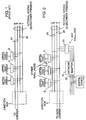
- POTS wiring in a subscriber premise typically comprises four signal wires as shown in Fig. 1. These wires extend to a junction box 4 that connects the customer premise to the carrier network. Inside the premise, these wires terminate at modular telephone jacks 2 located in the walls of the subscriber premise.
- G-R Green-Red
- B-Y Black-Yellow
- Fig. 2 illustrates an arrangement for linking both analogue and digital devices to a single subscription line in an ISDN network, using pre-existing telephone wires 24, 26.
- Telco carrier network wiring at the junction box 4 is connected to the spare pair of wires 26 and isolated from the formerly through-connected pair of wires 24.
- a network adapter 10 is plugged into any wall jack 2A (any one of the modular telephone jacks 2 in the POTS arrangement of Fig. 1).
- the network adapter 10 then serves as an interface between two wire subscriber loop signals on wires 26 in a standardized digital form, and S-bus 22 through which digital devices are connected.
- the digital and analogue interface network adapter 10 also serves as an interface between two wire subscriber loop signals on wires 26, in the standardized digital form, and analogue devices that connect to the G-R wire pair 24 via other wall jacks 2 (jacks other than jack 2A).
- the B-Y pre-existing wire pair 26 is adapted at the junction box 4 to interface with the Telco ISDN carrier network.
- the G-R pre-existing wire pair 24 is isolated from direct interface to the ISDN carrier network by disconnecting the pair at the junction box 4. In so doing, the G-R wires are "open" at the junction box but connected uniformly to analogue devices.
- the wiring change at the junction box may be adapted by manually changing the wires at the junction box.
- the S-bus wiring can be provided with a (usually short) cable extending from network adapter 10 to digital equipment located near the adapter (usually one device or set of devices sharing a single network port). Accordingly, the network adapter 10 is plugged into a modular telephone jack 2A at any desired (room, wall) location and the telco carrier interface is adapted as shown.
- the S-bus shown need not extend through any walls if all digital devices are in the same room as the adapter. However, the wiring scheme may require extended (additional) S-bus wiring for additional digital devices and terminal adapters.
- all signals flowing between the external telco carrier network and the customer premise are channelled through the network adapter 10 (via the internal B-Y pair 26 and the inside jack 2A to which the network adapter 10 is connected). All signals flowing between the network adapter 10 and digital devices run through the S-bus 22 interface between the network adapter 10 and the digital devices. All signals flowing between the network adapter 10 and any analogue device run through the R-G pair 24 between the jack 2A, at which the network adapter 10 is connected, and another jack 2, at which the analogue device is connected.
- signals flowing between any analogue device and the external carrier network pass in analogue form through the R-G pair linking the jack 2, at which the analogue device is connected, to the adapter 10; get converted in the adapter 10 between analogue and two wire digital ISDN forms; and pass in the latter form between the adapter 10 and the external carrier network, via the internal B-Y pair of wires 26 and the junction box 4.
- Signals flowing between any digital device and the external telco lines pass in digital form between the device and the adapter 10 via the S-bus 22; get converted in the adapter 10 between four wire S-bus digital form and two wire digital ISDN form; and pass in the latter form between the adapter 10 and the external carrier network, via the B-Y pair 26 and the junction box 4.
- Fig. 2 illustrates internal wiring at the subscriber premise configured as a single loop.
- analogue devices may be connected to the junction box 4 at any one of the modular telephone jacks 2 along the loop.
- alternate internal wiring configurations may be found at the subscriber premise, with another configuration presently contemplated being a star wiring configuration.
- a jack 2 at any branch of the star configuration may individually connect an analogue device to the junction box 4 (configuration not shown).
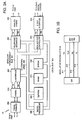
- the circuit includes a system microprocessor 350 which is connected by I/O control lines 302 to an E2PROM 360, U interface device 320, telephone interface 330 and ISDN access controller 390. While any appropriate microprocessor can be used, one suitable microprocessor is the 8031 which is sold by Intel.
- a suitable U interface device 320 is the PEB 2091; a suitable telephone interface 330 is the PEB 2160; a suitable ISDN access controller is the PEB 2086.
- Each of the PEB devices is sold by Siemens Components, Inc.
- a local bus 303 further connects the system microprocessor 350, SRAM 370, and EPROM 380.
- the local bus 303 comprises conductors used for transmitting address, data, or control signals between interconnected devices.
- modular interconnect bus 301 interconnects the U interface 320, telephone interface 330, and ISDN access controller 390.
- modular interconnect bus 301 consists of four discrete signal lines including a 8 Khz frame sync (FS) signal line 311, data clock (CLK) line 312, receive serial bit stream (RX) signal line 313, and a transmit serial bit stream (TX) signal line 314.
- FS frame sync
- CLK data clock
- RX receive serial bit stream
- TX transmit serial bit stream
- modular interconnect bus 301 serves to connect the U interface 320, telephone interface 330, and ISDN access controller 390
- bus 301 may also be used to connect other diverse voice/data modules (sources or targets for the D channel, or sources or targets for the B1 and B2 channels).
- the U interface device 320 is further connected to an input transformer 300 through a hybrid 310.
- the input transformer 300 is connectable to one pair of "through-connected" pre-existing telephone wires 26 within the subscriber premise and acts as a transformer and driver to the telephone network.
- the "through-connected" pair of telephone wires 26 is operatively connected to the telephone network but not coupled to any analogue devices within the subscriber premise.
- the pair of wires 26 may be the B-Y pair, according to the typical POTS configuration, as described.
- a signal coming from the telco network is first adapted at transformer 300 for input to the hybrid 310, where the signal is split into discrete transmit and receive signals. Partial cancellation of local echo and correct impedance matching to a four wire input for the U interface 320 is further performed by hybrid 310.
- the U interface 320 further conditions the incoming signal by performing echo cancellation and equalization on the four wire digital signals received, and converts the signals into a TTL level binary stream which contains digital information.
- the echo cancellation with hybrid (ECH) principle is one which supports full duplex operation over a two wire subscriber loop.
- the ECH method and resultant TTL level binary stream are in conformance with ANSI standard T1.601.
- the network adapter architecture 10 has been configured to interface with a BRI ISDN.
- the U interface 320 is of the type to accommodate a 2B1Q, or other standard digital channelized form as required by the local telephone network.
- 2B1Q line coding for example, pairs of bits are represented as one of four quantum levels. This is a four level pulse amplitude modulation (PAM) code without redundancy.
- the coded signal is a two wire subscriber loop signal characterized as having a frequency spectrum which is lower than the frequency spectrum of an uncoded digital signal.
- the two wire subscriber loop signal offers reduced line attenuation and crosstalk over the ISDN. In so doing, an 80 Khz 2B1Q two wire subscriber loop signal at the U interface may be converted into two discrete 160 kHz signals (transmit and receive).
- the ISDN access controller 390 is connected by S-bus interface 395 to S-bus 22.
- Interface 395 comprises a four wire interface at the S-bus 22 for connecting one or more digital devices within the subscriber premise.
- S-bus interface 395 contains a four wire transformer that supports up to eight digital devices according to the ANSI T1.605 standard.
- the telephone interface 330 is further connectable by analogue hybrid 340 to the other pair of pre-existing telephone wires 24 within the subscriber premise.
- the other pair of pre-existing telephone wires 24 is operatively connected to analogue devices within the subscriber premise; e.g., the G-R pair in the typical POTS configuration, as described.
- the other pair of pre-existing telephone wires 24, as distinguished from the first pair of pre-existing wires 26, is connected only to existing analogue devices within the subscriber premise (at jacks other than jack 2A).
- the analogue hybrid 340 is a subscriber line interface circuit providing drive, on-hook, and off-hook functions to the analogue devices and telco network.
- network adapter 10 are connectable to both pairs of pre-existing telephone wires 24, 26 through any modular telephone jack 2A. That is, a single plug serves to connect the network adapter 10 to both the carrier network and analogue devices.
- System microprocessor 350 controls its internal operation as well as interfacing with other elements of the network adapter 10.
- Fig. 4 there is illustrated a flow chart including the basic process steps used by microprocessor 350 in controlling the operation of the elements of the network adapter 10 as well as the flow of analogue and digital signals between U interface of the ISDN and digital and analogue devices.
- the coding of the process steps of this flow chart into the instructions suitable to control the microprocessor 350 will be understandable to one having ordinary skill in the art of programming.
- the flow chart of Fig. 4 is begun at start block 400, and the EPROM 380 (Fig. 3A) is adapted to store initial program load code, operational code, and power on diagnostics as indicated by block 410.
- the initial program load routine loads power on diagnostics from EPROM 380 into SRAM 370 at a specific address, indicated at step 410, and then vectors the system processor to begin executing power on diagnostics.
- the microprocessor 350 then checks whether the power on diagnostics routine has properly compiled and executed, and if it has not, the NO branch is taken from the decision block 420 to blocks 430 and 440 to set indicators and shutdown the network adapter 10 and ended at exit block 445.
- the YES branch is taken from the decision block 420 to block 450 where the microprocessor 350 loads initial program information (control program and operational code) from EPROM 380 into SRAM 370 at a specific address.
- initial program information control program and operational code
- the power on diagnostics and initial program load are well known routines. Moreover, the actual sequence of steps need not necessarily be limited to that described and may be otherwise arranged or combined.
- timing between network adapter 10 and the carrier network is checked, and if not in sync, the NO branch is taken from decision block 460 where the "return" output of block 460 is reapplied as input to the same block 460 which causes the logic to loop in a "ready” or “wait” state until synchronized timing between the network adapter and ISDN is established.
- the YES branch is taken from decision block 460 to block 470 labelled "PROC D CHAN" where the microprocessor 350 processes D channel control information located in a D channel buffer in the ISDN access controller 390.
- block 470 serves as input to block 480 labelled "PROC B CHAN" where the microprocessor 350 processes B channel digital voice or high-speed data.
- block 480 labelled "PROC B CHAN" where the microprocessor 350 processes B channel digital voice or high-speed data.
- the specific control functions of the adapter 10 at blocks 470 and 480 are illustrated in further detail in Figs. 5 through 7, and for the purpose of this description convert two wire subscriber loop signals carried on the one pair of pre-existing conventional telephone wires 26 between the standardized digital form used by the carrier network and an analogue form used by analogue devices on the other pair of pre-existing pair of telephone wires 24; and between the standardized digital form used by the carrier network and a digital form used by digital devices on the S-bus 22.
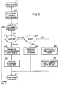
- FIGs. 5 and 6 flow diagrams are provided to illustrate in detail the operation of the microprocessor 350 during blocks shown at 470 in Fig. 4 when D channel control for the flow of analogue and digital signals between U interface of the ISDN and digital and analogue devices is actually occurring.
- the coding of the process steps used by the microprocessor 350 into instructions suitable to control the microprocessor 350 will be understood by one having ordinary skill in the art.
- the microprocessor 350 uses LAPD protocol within the ISDN access controller 390 to process D channel data at block 505. Call processing of this data is performed according to CCITT spec Q.931 which comprises processing carrier network and adapter 10 functions for both incoming and outgoing calls.
- the microprocessor 350 determines first whether a valid D channel message is present. If no message is present, the NO branch is taken from decision block 510 to block 685 (Fig. 6). Otherwise, the YES branch is taken to block 515 where the nature of incoming B channel signal to be processed is determined.
- the ANALOGUE branch is taken from the decision block 515 to block 520, where the status of the targeted analogue device addressed by the incoming call is determined. If the targeted device is busy, the YES branch of decision block 520 is taken to block 550 where a busy signal is submitted as a response to the carrier network. If available, the NO branch of decision block is take to blocks 560 and 570 where the microprocessor 350 accepts the call, rings the targeted analogue device, monitors the switch hook of the targeted analogue device, and activates the analogue call upon the lifting, or otherwise enabling, the switch hook of the targeted analogue device.
- the DIGITAL branch of decision block 515 is taken to blocks 530 and 540.
- all incoming set up messages for digital calls are passed to the S-bus 22.
- D channel echo bits are used to allow any digital device on the S-bus to initiate transmission over the D-channel at block 540.
- the microprocessor 350 upon completing D channel control processing for incoming analogue and digital signals (Fig. 5), the microprocessor 350 then continues, at block 605, with D channel control processing for outgoing analogue and digital signals where at block 610 the nature of an outgoing call is determined. If an analogue call is detected, the ANALOGUE branch is taken from the decision block 610 to block 620, where the status of a dial tone at the requesting analogue device is monitored. The microprocessor 350 waits for a number to be entered by the requesting analogue device, and if no number is entered within a "time out" period, the YES branch of decision block 620 is taken to block 630 where an "off hook" signal is sent to the requesting device.
- the NO branch of decision block is taken to block 635 where the microprocessor awaits a valid number from the requesting analogue device, and while this has not yet occurred, the NO branch of decision block 635 serves as input to the same block 635 and serves to "wait” or "hold” until a valid number has been entered. Otherwise, the YES branch of decision block 635 is taken to block 640 where an the microprocessor 350 issues instructions to initiate and outgoing analogue call. These instructions command the microprocessor to connect the requesting analogue device to a designated telephone number.
- the adapter 10 serves to interface between the requesting analogue device and the device associated with the designated telephone number, and further serves to convert signals between an analogue form, associated with the requesting analogue device, and a standardized digital form, associated with the two wire subscriber loop.
- D channel echo bits are used to allow any digital device on the S-bus to gain access to the network to initiate transmission over the D channel.
- the adapter's 10 primary responsibilities are to control all D channel signal transfers between the network and analogue devices, and to act as a routing mechanism and "relay" with respect to D channel signal transfers running between the network and digital devices attached to the S bus 22 (relay in the sense that the adapter does not alter the information context or form of the signals being transferred).
- the adapter 10 could be provided with an RS 232 port for connecting to devices that are adapted for RS 232 signalling.
- the adapter 10 could act as the master with respect to originating D channel signals to the network and interpreting D channel signals coming from the network (converting non-ISDN interface functions into an ISDN acceptable form relative to devices attached to its RS 232 port).
- the processing of incoming digital signals could include additional function at the adapter 10 such as checking whether the targeted digital device is available, responding with a busy signal, or accepting the digital call and activating the 64 kbps digital B channel.
- the processing of outgoing digital signals could include additional function at the adapter 10 such as initiating an outgoing call, checking whether the device associated with the designated telephone number is available, posting a "no-connect" signal if unavailable, or completing a call path to the device associated with the designated telephone number.
- FIG. 7 flow diagrams are provided to illustrate in detail the operation of the microprocessor 350 during block shown at 480 in Fig. 4 when B channel processing of digital voice or high speed date is actually occurring. Again, the coding of the process steps used by the microprocessor 350 into instructions suitable to control the microprocessor 350 will be understood by one having ordinary skill in the art.
- Fig. 7 The flow chart of Fig. 7 is begun at start block 705, and initially it is determined whether an analogue call is active, and if not, the NO branch of decision block 710 is taken to block 790 where B channel digital data is processed. Otherwise, if an analogue call is active, the YES branch of decision block 710 is taken to block 720 where the state of the originating analogue device is checked. If an "off hook" state of the originating analogue device is sensed by the telephone interface 330, the OFF HOOK branch of decision block 720 is taken to block 730 where a dial tone is transmitted to the originating analogue device.
- the DIALING branch of decision block 720 is taken to block 740 where DTMF decode information is sent via the D channel to be processed by ISDN access controller 390. If a call is currently "active", the ACTIVE branch of decision block 720 is taken to block 750 where data is taken from the telephone interface 330 and transmitted over an ISDN B channel at block 750.
- the INCOMING branch of decision block 760 is taken to block 780 where a ring signal is applied to the analogue telephone addressed by the incoming call. If the status of the incoming signal is that of a currently active signal, the ACTIVE branch of decision block 760 is taken to block 770 where the incoming signal is received by telephone interface 330 and transmitted to the analogue telephone addressed by the incoming call via the analogue hybrid 340. Having processed analogue channel information, digital information is processed at block 780.
- a communication system in a two wire subscriber carrier network has been described. It comprises: two pair of internal telephone wires, wherein one pair of said internal telephone wires is connected to said carrier network and the other pair is isolated from said carrier network; an adapter for processing signals; first means for interfacing said adapter to said two pair of internal telephone wires; and converting means for converting signals between said one of said two pair of internal telephone wires and said other of said two pair of internal telephone wires so as to sustain communication between signals on said carrier network and devices on said other pair of internal telephone wires.
- the communication system further comprises: second interfacing means for interfacing said adapter to a digital device; and said converting means further converting signals between said one of said two pair of internal telephone wires and said second interfacing means so as to sustain communication between signals on said carrier network and said digital device. Also, said converting means concurrently sustains communication between signals on said carrier network and said analogue devices on said other pair of internal telephone wires and between signals on said carrier network and said digital device on said second means for interfacing.
Landscapes
- Engineering & Computer Science (AREA)
- Signal Processing (AREA)
- Computer Networks & Wireless Communication (AREA)
- Telephonic Communication Services (AREA)
- Data Exchanges In Wide-Area Networks (AREA)
- Sub-Exchange Stations And Push- Button Telephones (AREA)
Applications Claiming Priority (2)
| Application Number | Priority Date | Filing Date | Title |
|---|---|---|---|
| US08/085,333 US5448635A (en) | 1993-06-30 | 1993-06-30 | Wiring scheme and network adapter with digital and analog outputs to allow old pots coexistence with ISDN |
| US85333 | 1993-06-30 |
Publications (3)
| Publication Number | Publication Date |
|---|---|
| EP0637183A2 true EP0637183A2 (fr) | 1995-02-01 |
| EP0637183A3 EP0637183A3 (fr) | 2002-06-12 |
| EP0637183B1 EP0637183B1 (fr) | 2006-03-08 |
Family
ID=22190907
Family Applications (1)
| Application Number | Title | Priority Date | Filing Date |
|---|---|---|---|
| EP94110159A Expired - Lifetime EP0637183B1 (fr) | 1993-06-30 | 1994-06-30 | Réseau aux sorties numériques et analogues |
Country Status (5)
| Country | Link |
|---|---|
| US (1) | US5448635A (fr) |
| EP (1) | EP0637183B1 (fr) |
| JP (1) | JP2745495B2 (fr) |
| CA (1) | CA2122934C (fr) |
| DE (1) | DE69434646T2 (fr) |
Cited By (2)
| Publication number | Priority date | Publication date | Assignee | Title |
|---|---|---|---|---|
| WO1997047157A1 (fr) * | 1996-06-07 | 1997-12-11 | Gpt Limited | Systemes en boucle, a large bande et numeriques, destines a des abonnes |
| EP0690652A3 (fr) * | 1994-06-27 | 1998-09-30 | International Business Machines Corporation | Méthode de réalisation de services de réseau intelligents avec une terminaison de réseau RNI |
Families Citing this family (56)
| Publication number | Priority date | Publication date | Assignee | Title |
|---|---|---|---|---|
| US6310940B1 (en) * | 1966-12-16 | 2001-10-30 | Ncr Corporation | Personal computer interactive phone system |
| EP0836351A3 (fr) * | 1990-11-29 | 1999-06-02 | Fujitsu Limited | Interface RNIS |
| US5629926A (en) * | 1995-03-31 | 1997-05-13 | Lucent Technologies Inc. | Customer premise equipment interface |
| US5577115A (en) * | 1995-03-31 | 1996-11-19 | Lucent Technologies Inc. | Customer premise equipment interface |
| US5903643A (en) * | 1995-06-02 | 1999-05-11 | Teleport Communications Group, Inc. | Multi-line station interface |
| US5612995A (en) * | 1995-12-22 | 1997-03-18 | Lucent Technologies Inc. | Method for activating a lamp on analog customer premises equipment by a digital signal |
| US5862134A (en) * | 1995-12-29 | 1999-01-19 | Gte Laboratories Incorporated | Single-wiring network for integrated voice and data communications |
| US6373852B1 (en) * | 1996-07-15 | 2002-04-16 | At&T Corp. | Coupling multiple low data rate lines to effect high data rate communication |
| US5923671A (en) * | 1996-07-22 | 1999-07-13 | At&T Corp | Coupling multiple low data rate lines to effect high data rate communication |
| US6118766A (en) * | 1996-08-21 | 2000-09-12 | Godigital Networks Corporation | Multiple ISDN carrier system |
| US6295357B1 (en) * | 1996-09-06 | 2001-09-25 | Data Race, Inc. | System and method for ringing other subscriber telephones connected to a telephone line during data communications on the telephone line |
| US5896512A (en) * | 1996-09-11 | 1999-04-20 | Lucent Technologies Inc. | Modified network interface unit with terminal device access |
| US6141330A (en) * | 1996-09-20 | 2000-10-31 | Godigital Networks Corporation | Multiple ISDN and pots carrier system |
| US6370149B1 (en) | 1998-07-20 | 2002-04-09 | Ameritech Corporation | Telecommunication system, method and subscriber unit for use therein |
| US7187686B1 (en) | 1996-11-01 | 2007-03-06 | Sbc Properties, B.P. | Telecommunication system, method and subscriber unit for use therein |
| US5883941A (en) * | 1996-11-08 | 1999-03-16 | Godigital Telecommunications | HDSL and POTS carrier system |
| US5848150A (en) * | 1997-02-26 | 1998-12-08 | Paradyne Corporation | Passive distributed filter system and method |
| CA2275274A1 (fr) * | 1996-12-17 | 1998-06-25 | Paradyne Corporation | Systeme de filtres passifs repartis et procede correspondant |
| US5889856A (en) * | 1997-05-22 | 1999-03-30 | Centillium Technology Corp. | ADSL integrated line card with digital splitter and POTS CODEC without bulky analog splitter |
| US5949763A (en) | 1997-07-17 | 1999-09-07 | Ameritech Corporation | Method and apparatus for providing broadband access conferencing services |
| WO1999021311A1 (fr) * | 1997-10-20 | 1999-04-29 | Godigital Telecommunications | Systeme a courants porteurs multiples rnis et pots |
| US6141356A (en) * | 1997-11-10 | 2000-10-31 | Ameritech Corporation | System and method for distributing voice and data information over wireless and wireline networks |
| US6215799B1 (en) | 1997-11-24 | 2001-04-10 | 3Com Corporation | Analog telephone to ISDN interface apparatus and method therefor |
| US6172985B1 (en) | 1998-01-28 | 2001-01-09 | Gateway 2000, Inc. | Automatic detection of pots line |
| US6522640B2 (en) | 1998-01-28 | 2003-02-18 | Gateway, Inc. | Distributed modem for non-cellular cordless/wireless data communication for portable computers |
| US6480510B1 (en) | 1998-07-28 | 2002-11-12 | Serconet Ltd. | Local area network of serial intelligent cells |
| US6335936B1 (en) * | 1999-04-22 | 2002-01-01 | Ameritech Corporation | Wide area communication networking |
| US6512764B1 (en) | 1999-07-16 | 2003-01-28 | General Bandwidth Inc. | Method and apparatus for providing voice signals to and from a telecommunications switch |
| DE19952303A1 (de) | 1999-10-29 | 2001-05-10 | Siemens Ag | Schaltungsanordnung und Verfahren zur Datenübertragung |
| US6466573B1 (en) | 2000-02-11 | 2002-10-15 | General Bandwidth Inc. | System and method for communicating telecommunication information between a telecommunication switch and customer premises equipment |
| US6404763B1 (en) | 2000-02-11 | 2002-06-11 | General Bandwidth Inc. | System and method for communicating telecommunication information between network equipment and a plurality of local loop circuits |
| US6512762B1 (en) | 2000-02-11 | 2003-01-28 | General Bandwidth, Inc. | System and method for communicating telecommunication information between customer premises equipment and network equipment |
| US7068682B2 (en) * | 2000-02-28 | 2006-06-27 | Qwest Communications International Inc. | Signal distribution within customer premises |
| US6549616B1 (en) | 2000-03-20 | 2003-04-15 | Serconet Ltd. | Telephone outlet for implementing a local area network over telephone lines and a local area network using such outlets |
| IL135744A (en) | 2000-04-18 | 2008-08-07 | Mosaid Technologies Inc | Telephone communication system over a single telephone line |
| US6842459B1 (en) | 2000-04-19 | 2005-01-11 | Serconet Ltd. | Network combining wired and non-wired segments |
| US6850618B1 (en) | 2000-05-15 | 2005-02-01 | Centillium Communications, Inc. | Central office interface techniques for digital subscriber lines |
| US7675900B1 (en) | 2000-10-09 | 2010-03-09 | Genband Inc. | System and method for interfacing between signaling protocols |
| US6839342B1 (en) | 2000-10-09 | 2005-01-04 | General Bandwidth Inc. | System and method for interfacing signaling information and voice traffic |
| US7385963B1 (en) | 2000-11-28 | 2008-06-10 | Genband Inc. | System and method for communicating telecommunication information from a telecommunication network to a broadband network |
| US7184427B1 (en) | 2000-11-28 | 2007-02-27 | Genband Inc. | System and method for communicating telecommunication information from a broadband network to a telecommunication network |
| US6754221B1 (en) | 2001-02-15 | 2004-06-22 | General Bandwidth Inc. | System and method for selecting a compression algorithm according to an available bandwidth |
| US6526046B1 (en) | 2001-04-24 | 2003-02-25 | General Bandwidth Inc. | System and method for communicating telecommunication information using asynchronous transfer mode |
| US7149182B1 (en) | 2001-04-24 | 2006-12-12 | Genband Inc. | System and method for providing lifeline telecommunication service |
| US6879667B1 (en) | 2001-05-07 | 2005-04-12 | General Bandwidth Inc. | System and method for interfacing telephony voice signals with a broadband access network |
| US6996134B1 (en) | 2001-05-07 | 2006-02-07 | General Bandwidth Inc. | System and method for reliably communicating telecommunication information |
| IL144158A (en) | 2001-07-05 | 2011-06-30 | Mosaid Technologies Inc | Socket for connecting an analog telephone to a digital communications network that carries digital voice signals |
| US7245583B1 (en) | 2001-09-04 | 2007-07-17 | Genband Inc. | System and method for providing lifeline telecommunication service to line-powered customer premises equipment |
| US7170854B1 (en) | 2001-10-02 | 2007-01-30 | Genband Inc. | System and method using switch fabric to support redundant network ports |
| IL161190A0 (en) | 2001-10-11 | 2004-08-31 | Serconet Ltd | Outlet with analog signal adapter, method for use thereof and a network using said outlet |
| US7127043B2 (en) * | 2001-11-01 | 2006-10-24 | Net2Phone, Inc. | Secondary subscriber line override system and method |
| US7239628B1 (en) | 2002-05-01 | 2007-07-03 | Genband Inc. | Line-powered network interface device |
| US6975713B1 (en) * | 2003-03-13 | 2005-12-13 | Vulcan Research LLC | Providing multiple line functionality using alternative network telephony |
| IL154921A (en) | 2003-03-13 | 2011-02-28 | Mosaid Technologies Inc | A telephone system that includes many separate sources and accessories for it |
| IL159838A0 (en) | 2004-01-13 | 2004-06-20 | Yehuda Binder | Information device |
| US7873058B2 (en) | 2004-11-08 | 2011-01-18 | Mosaid Technologies Incorporated | Outlet with analog signal adapter, a method for use thereof and a network using said outlet |
Family Cites Families (16)
| Publication number | Priority date | Publication date | Assignee | Title |
|---|---|---|---|---|
| US4972463A (en) * | 1986-09-15 | 1990-11-20 | Norand Corporation | In-store multiple device communications unit and centralized data system utilizing same |
| US4932022A (en) * | 1987-10-07 | 1990-06-05 | Telenova, Inc. | Integrated voice and data telephone system |
| US4924492A (en) * | 1988-03-22 | 1990-05-08 | American Telephone And Telegraph Company | Method and apparatus for wideband transmission of digital signals between, for example, a telephone central office and customer premises |
| US4853949A (en) * | 1988-03-24 | 1989-08-01 | Rockwell International Corporation | Fail safe voice system for integrated services for digital network subscribers |
| US4884269A (en) * | 1988-06-20 | 1989-11-28 | Hayes Microcomputer Products, Inc. | Method and apparatus for connecting ISDN devices over an analog telephone line |
| US4970723A (en) * | 1988-09-30 | 1990-11-13 | At&T Bell Laboratories | ISDN, basic rate interface arranged for quad voice |
| US4885769A (en) * | 1988-12-23 | 1989-12-05 | Nynex Corporation | Station controller for enhanced multi-line pick-up in centrex exchange telephone system |
| US5023869A (en) * | 1989-03-27 | 1991-06-11 | Alberta Telecommunications Research Centre | Method and apparatus for maximizing the transmission capacity of a multi-channel bidirectional communications link |
| DE3917029C1 (en) * | 1989-05-24 | 1990-10-31 | Kapsch Ag, Wien, At | ISDN communications system termination unit - uses microprocessors to facilitate exchanges, and has converters coupled to multiplexing line |
| DE3923125A1 (de) * | 1989-07-13 | 1991-01-24 | Standard Elektrik Lorenz Ag | Universelle isdn-teilnehmeranschlussbaugruppe |
| DE69025852T2 (de) * | 1989-10-23 | 1996-08-29 | At & T Corp | Anordnung für die Steuerung eines digitalen Verzweigerschalters von einem Vermittlungssystem aus |
| DE4008450A1 (de) * | 1990-03-16 | 1991-09-19 | Telefonbau & Normalzeit Gmbh | Schaltungsanordnung zur signal- und informationsumsetzung zwischen analog betriebenen verbindungsleitungen und digital betriebenen anschlussorganen in kommunikations-vermittlungsanlagen |
| US5157656A (en) * | 1990-07-31 | 1992-10-20 | Northern Telecom Limited | Nyblet time switch |
| US5195125A (en) * | 1990-09-17 | 1993-03-16 | Raychem Corporation | Gel filled RJ11 connector |
| US5191456A (en) * | 1991-07-30 | 1993-03-02 | Alcatel Network Systems, Inc. | Efficient feeder fiber loading from distribution fibers |
| US5305312A (en) * | 1992-02-07 | 1994-04-19 | At&T Bell Laboratories | Apparatus for interfacing analog telephones and digital data terminals to an ISDN line |
-
1993
- 1993-06-30 US US08/085,333 patent/US5448635A/en not_active Expired - Fee Related
-
1994
- 1994-05-05 CA CA002122934A patent/CA2122934C/fr not_active Expired - Fee Related
- 1994-06-13 JP JP6130676A patent/JP2745495B2/ja not_active Expired - Fee Related
- 1994-06-30 EP EP94110159A patent/EP0637183B1/fr not_active Expired - Lifetime
- 1994-06-30 DE DE69434646T patent/DE69434646T2/de not_active Expired - Fee Related
Cited By (2)
| Publication number | Priority date | Publication date | Assignee | Title |
|---|---|---|---|---|
| EP0690652A3 (fr) * | 1994-06-27 | 1998-09-30 | International Business Machines Corporation | Méthode de réalisation de services de réseau intelligents avec une terminaison de réseau RNI |
| WO1997047157A1 (fr) * | 1996-06-07 | 1997-12-11 | Gpt Limited | Systemes en boucle, a large bande et numeriques, destines a des abonnes |
Also Published As
| Publication number | Publication date |
|---|---|
| EP0637183B1 (fr) | 2006-03-08 |
| DE69434646T2 (de) | 2006-09-14 |
| EP0637183A3 (fr) | 2002-06-12 |
| CA2122934A1 (fr) | 1994-12-31 |
| CA2122934C (fr) | 1998-04-14 |
| JPH0758745A (ja) | 1995-03-03 |
| JP2745495B2 (ja) | 1998-04-28 |
| DE69434646D1 (de) | 2006-05-04 |
| US5448635A (en) | 1995-09-05 |
Similar Documents
| Publication | Publication Date | Title |
|---|---|---|
| US5448635A (en) | Wiring scheme and network adapter with digital and analog outputs to allow old pots coexistence with ISDN | |
| CA2148384C (fr) | Methodes pour offrir des services intelligents via un rnis au moyen d'un terminal installe chez l'abonne | |
| JP5043136B2 (ja) | 単一電話ライン上の電話通信システム | |
| EP0361760B1 (fr) | Interface RNIS à débit de base arrangée pour la quadriforme | |
| US5625685A (en) | Network termination unit | |
| EP0796020A2 (fr) | Système et méthode de signalisation permettant la transparence de caractéristiques entre des centraux téléphoniques privés à travers un réseau public commuté | |
| JPH0685962A (ja) | 通信装置 | |
| GB2257330A (en) | Remote maintenance of a private branch exchange system | |
| US4905237A (en) | Communications system comprising an ISDN terminal equipment connection for different ISDN interfaces in an ISDN switching equipment network | |
| US4689788A (en) | Method and apparatus for implementing a cost efficient voice/data communication system with a conventional PBX switch | |
| US6034953A (en) | System for local voice distribution by an ISDN communications controller | |
| USRE38596E1 (en) | Methods for performing intelligent network services with an ISDN network terminator located at a subscriber's premise | |
| US5715300A (en) | Method for establishing data connections in an auxiliary exchange communications installation | |
| US6009084A (en) | Concentrating transmultiplexer for cable telephony | |
| EP1093278A2 (fr) | Un réseau d'accès basé sur le Protocol Internet | |
| CA2412762C (fr) | Methodes pour offrir des services intelligents via un rnis au moyen d'un terminal installe chez l'abonne | |
| US6243390B1 (en) | ISDN communications controller | |
| Casaca | Integrated services networks | |
| JPH0286349A (ja) | 端末装置の接続方式 | |
| JPH10126515A (ja) | データストリーム変換装置 | |
| JPH0290847A (ja) | 自動交換機システムのシステムデータ出力方式 | |
| IL129753A (en) | Expanded home lan | |
| GB2255876A (en) | Telecommunications system | |
| WO2002102094A1 (fr) | Caracteristique d'intracommunication pour reseau d'acces |
Legal Events
| Date | Code | Title | Description |
|---|---|---|---|
| PUAI | Public reference made under article 153(3) epc to a published international application that has entered the european phase |
Free format text: ORIGINAL CODE: 0009012 |
|
| AK | Designated contracting states |
Kind code of ref document: A2 Designated state(s): DE FR GB |
|
| 17P | Request for examination filed |
Effective date: 19950425 |
|
| PUAL | Search report despatched |
Free format text: ORIGINAL CODE: 0009013 |
|
| AK | Designated contracting states |
Kind code of ref document: A3 Designated state(s): DE FR GB |
|
| 17Q | First examination report despatched |
Effective date: 20020812 |
|
| GRAP | Despatch of communication of intention to grant a patent |
Free format text: ORIGINAL CODE: EPIDOSNIGR1 |
|
| GRAS | Grant fee paid |
Free format text: ORIGINAL CODE: EPIDOSNIGR3 |
|
| GRAA | (expected) grant |
Free format text: ORIGINAL CODE: 0009210 |
|
| AK | Designated contracting states |
Kind code of ref document: B1 Designated state(s): DE FR GB |
|
| REG | Reference to a national code |
Ref country code: GB Ref legal event code: FG4D |
|
| REF | Corresponds to: |
Ref document number: 69434646 Country of ref document: DE Date of ref document: 20060504 Kind code of ref document: P |
|
| ET | Fr: translation filed | ||
| PLBE | No opposition filed within time limit |
Free format text: ORIGINAL CODE: 0009261 |
|
| STAA | Information on the status of an ep patent application or granted ep patent |
Free format text: STATUS: NO OPPOSITION FILED WITHIN TIME LIMIT |
|
| 26N | No opposition filed |
Effective date: 20061211 |
|
| REG | Reference to a national code |
Ref country code: GB Ref legal event code: 746 Effective date: 20090519 |
|
| PGFP | Annual fee paid to national office [announced via postgrant information from national office to epo] |
Ref country code: DE Payment date: 20090626 Year of fee payment: 16 |
|
| PG25 | Lapsed in a contracting state [announced via postgrant information from national office to epo] |
Ref country code: DE Free format text: LAPSE BECAUSE OF NON-PAYMENT OF DUE FEES Effective date: 20110101 |
|
| PGFP | Annual fee paid to national office [announced via postgrant information from national office to epo] |
Ref country code: FR Payment date: 20110630 Year of fee payment: 18 |
|
| REG | Reference to a national code |
Ref country code: FR Ref legal event code: ST Effective date: 20130228 |
|
| PG25 | Lapsed in a contracting state [announced via postgrant information from national office to epo] |
Ref country code: FR Free format text: LAPSE BECAUSE OF NON-PAYMENT OF DUE FEES Effective date: 20120702 |
|
| PGFP | Annual fee paid to national office [announced via postgrant information from national office to epo] |
Ref country code: GB Payment date: 20130624 Year of fee payment: 20 |
|
| REG | Reference to a national code |
Ref country code: GB Ref legal event code: PE20 Expiry date: 20140629 |
|
| PG25 | Lapsed in a contracting state [announced via postgrant information from national office to epo] |
Ref country code: GB Free format text: LAPSE BECAUSE OF EXPIRATION OF PROTECTION Effective date: 20140629 |