EP0637371B1 - Vorrichtung zum messen des winkels eines werkstückes - Google Patents
Vorrichtung zum messen des winkels eines werkstückes Download PDFInfo
- Publication number
- EP0637371B1 EP0637371B1 EP94907078A EP94907078A EP0637371B1 EP 0637371 B1 EP0637371 B1 EP 0637371B1 EP 94907078 A EP94907078 A EP 94907078A EP 94907078 A EP94907078 A EP 94907078A EP 0637371 B1 EP0637371 B1 EP 0637371B1
- Authority
- EP
- European Patent Office
- Prior art keywords
- feelers
- base
- piece
- feeler
- angle
- Prior art date
- Legal status (The legal status is an assumption and is not a legal conclusion. Google has not performed a legal analysis and makes no representation as to the accuracy of the status listed.)
- Expired - Lifetime
Links
- 238000005259 measurement Methods 0.000 claims abstract description 18
- 238000005452 bending Methods 0.000 claims description 39
- 239000002184 metal Substances 0.000 claims description 20
- 239000000463 material Substances 0.000 claims description 5
- 230000000295 complement effect Effects 0.000 claims 1
- 230000007423 decrease Effects 0.000 claims 1
- 230000000694 effects Effects 0.000 claims 1
- 239000007787 solid Substances 0.000 claims 1
- 239000000523 sample Substances 0.000 description 5
- 230000003746 surface roughness Effects 0.000 description 3
- 229910000831 Steel Inorganic materials 0.000 description 2
- 230000015572 biosynthetic process Effects 0.000 description 2
- 239000010959 steel Substances 0.000 description 2
- 229910000760 Hardened steel Inorganic materials 0.000 description 1
- 230000006835 compression Effects 0.000 description 1
- 238000007906 compression Methods 0.000 description 1
- 238000012937 correction Methods 0.000 description 1
- 238000010586 diagram Methods 0.000 description 1
- 238000004519 manufacturing process Methods 0.000 description 1
- 238000000034 method Methods 0.000 description 1
Images


Classifications
-
- B—PERFORMING OPERATIONS; TRANSPORTING
- B21—MECHANICAL METAL-WORKING WITHOUT ESSENTIALLY REMOVING MATERIAL; PUNCHING METAL
- B21D—WORKING OR PROCESSING OF SHEET METAL OR METAL TUBES, RODS OR PROFILES WITHOUT ESSENTIALLY REMOVING MATERIAL; PUNCHING METAL
- B21D5/00—Bending sheet metal along straight lines, e.g. to form simple curves
- B21D5/02—Bending sheet metal along straight lines, e.g. to form simple curves on press brakes without making use of clamping means
- B21D5/0209—Tools therefor
-
- G—PHYSICS
- G01—MEASURING; TESTING
- G01B—MEASURING LENGTH, THICKNESS OR SIMILAR LINEAR DIMENSIONS; MEASURING ANGLES; MEASURING AREAS; MEASURING IRREGULARITIES OF SURFACES OR CONTOURS
- G01B5/00—Measuring arrangements characterised by the use of mechanical techniques
- G01B5/24—Measuring arrangements characterised by the use of mechanical techniques for measuring angles or tapers; for testing the alignment of axes
-
- G—PHYSICS
- G01—MEASURING; TESTING
- G01B—MEASURING LENGTH, THICKNESS OR SIMILAR LINEAR DIMENSIONS; MEASURING ANGLES; MEASURING AREAS; MEASURING IRREGULARITIES OF SURFACES OR CONTOURS
- G01B7/00—Measuring arrangements characterised by the use of electric or magnetic techniques
- G01B7/30—Measuring arrangements characterised by the use of electric or magnetic techniques for measuring angles or tapers; for testing the alignment of axes
-
- Y—GENERAL TAGGING OF NEW TECHNOLOGICAL DEVELOPMENTS; GENERAL TAGGING OF CROSS-SECTIONAL TECHNOLOGIES SPANNING OVER SEVERAL SECTIONS OF THE IPC; TECHNICAL SUBJECTS COVERED BY FORMER USPC CROSS-REFERENCE ART COLLECTIONS [XRACs] AND DIGESTS
- Y10—TECHNICAL SUBJECTS COVERED BY FORMER USPC
- Y10S—TECHNICAL SUBJECTS COVERED BY FORMER USPC CROSS-REFERENCE ART COLLECTIONS [XRACs] AND DIGESTS
- Y10S72/00—Metal deforming
- Y10S72/702—Overbending to compensate for springback
Definitions
- the present invention relates to a device for measuring an angle in a piece, particularly an angle formed in a piece of sheet metal by bending, during the operation to bend the piece in a bending press having a punch and a V-shaped die which cooperate with each other.
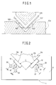
- One of these known devices provides for the use of two or more distance-measuring sensors 100 disposed on each face 102 of the V-shaped groove in the die 104.
- This known device calculates the angle formed in the piece by bending, by means of direct distance measurements between the surface of the piece and the respective wall 102 of the V-shaped groove in the die 104, made with pointed feelers 100 at two points spaced a known distance apart in a direction perpendicular to the bending line.
- the object of the present invention is to provide a device for measuring an angle in a piece, which is not affected by the aforementioned disadvantages and which provides very precise and reproducible measurements regardless of the condition of the surface of the piece.
- this object is achieved by the provision of a device having the characteristics forming the subject of Claim 1.
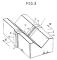
- a device is for measuring an angle formed in a piece of sheet metal 2 by bending, during a bending operation carried out on the piece by means of a bending press comprising a punch 4 and a die 6.
- the device 1 comprises a base 8 constituted by a steel plate a few millimeters thick with holes 10 for enabling it to be fixed between two bodies 11 so as to form a compact block which is inserted in a slot 13 in the die 6.
- the device 1 has two feelers 12 disposed approximately symmetrically with respect to an axis A which passes through the vertex of the V-shaped groove 14 in the die 6.
- Each feeler 12 has an active surface 16 which extends beyond the respective wall of the groove 14. The active surfaces 16 of the feelers 12 are thus intended to contact respective portions 2a. 2b of the piece being bent.
- each feeler 12 is connected to the base 8 by means of two connecting elements 18 formed integrally with the base 8 and with the feeler 12.
- the connecting elements 18 are constituted by thin, multiple-S-shaped strips of material.
- the particular system for connecting the feelers 12 to the base 8 means that the feelers 12 are completely free of each other kinematically.
- the connecting elements 18 also constitute resilient thrust means which allow each feeler 12 to perform a translatory and a pivoting movement relative to the base 8, within a plane perpendicular to the bending line, completely independently of the movement of the other feeler.
- Each feeler 12 is H-shaped with two portions 20, 22 joined together by a central web 24.
- the connecting and thrust elements 18 are very flexible in a direction perpendicular to the active surfaces 16 of the respective feelers 12.
- the feelers 12 and the connecting and thrust elements 18 are formed integrally from a steel plate constituting the base 8. More precisely, each feeler 12 and its connecting and thrust elements 18 are produced by the removal of material from the region 26 which is shaded in Figure 4a.
- the base 8 is made of a hardened steel with a high yield point, of the type used for the manufacture of springs.
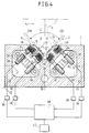
- each support 30 carries a pair of distance-measuring sensors 32 formed according to the prior art, which are housed - parallel to each other - and lying in a plane perpendicular to the vertex of the V-shaped groove 14, in a chamber 33 defined between the two bodies 11.
- Each sensor 32 faces a respective corresponding element 34 fixed to the feeler 12.
- the sensors 32 are high-sensitivity contactless electromagnetic probes which generate magnetic fields, the intensities of which depend upon the distances between the corresponding elements 34 and the end surfaces of the sensors 32.
- the surfaces of the corresponding elements 34 which face the sensors 32 are approximately parallel to the active surfaces 16 of the feelers 12.
- Each sensor 32 is connected to an amplifier 36 which sends a signal indicative of the distance measured to a control unit 38.
- the control unit 38 operates a numerically-controlled actuator 40 which brings about the relative movement of the bending tools 4, 6.
- a sample punch with a vertex angle V ⁇ which is known with an accuracy equal to or better than that with which the subsequent measurements are to be made is mounted on the press instead of the bending punch.
- V ⁇ vertex angle
- the active surfaces 16 of the feelers 12 which are acted on by the connecting and thrust elements 18 adapt precisely to the surfaces of the sample element.
- the distance measurements supplied by the four sensors 32 are stored by the control unit 38 and adopted as reference values for the subsequent measurements.
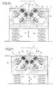
- a flat piece of sheet metal 2 is placed on the die 6 in a position perpendicular to the bending plane defined by the direction of the relative movement of the punch 4 and the die 6 ( Figure 6).
- the punch 4 which is operated by the actuator 40, controlled by the control unit 38, then enters the groove 14 in the die 6 forming a bend in the piece 2 ( Figure 7).
- the feelers 12 are retracted relative to the walls of the groove 14 against the resilient action of the connecting and thrust elements 18.
- the relative bending travel of the tools 4, 6 corresponds to a bending angle C slightly smaller than the desired value.
- the tools 4, 6 are moved apart far enough to leave the sheet metal free so that the two portions 2a, 2b of the piece being worked can return resiliently (Figure 8).
- the sheet metal 2 is in a generic position relative to the groove 14 and the vertex of the sheet-metal dihedron remains sufficiently parallel to the vertex of the V-shaped groove 14.
- the active surfaces 16 of the feelers 12 are kept in contact with the respective portions 2a, 2b of the piece 2 by the resilient force exerted by the connecting and thrust elements 18.
- the feelers 12 can adapt precisely to the position adopted by the piece 2, since each feeler is free to move within the plane, independently of the other.
- the feelers 12 thus adopt angular orientations the same as those of the portions 2a, 2b of the piece 2. These angular orientations are also independent of the distances of the feelers 12 from the vertex of the bent sheet-metal dihedron. These distances may even be different for the two feelers 12.
- the contact between the feelers 12 and the piece 2 takes place over a large surface 16 and therefore the determination of the bending angle is not affected by the surface roughness of the piece.
- the distance-measuring sensors 32 associated with each feeler 12 are spaced a known distance apart so that the control unit 38 can determine the actual angle C formed in the bent piece by comparing the distance measurements provided by the four sensors 32 with those obtained during the calibration.
- the control unit 38 checks the bend angle, measured against the desired bend angle, and operates the actuator 40 again so as to make the distance D between the vertices of the tools 4, 6 slightly less than the distance set during the preliminary bending.
- the method described is repeated until the distance D determined corresponds to the desired bend angle C.
- This value is then stored and is used for all the subsequent bending operations on pieces having the same physical characteristics.
- the device 1 enables the bend angle of the piece to be measured continuously and corrections to be made, should the need arise.
- FIG. 9 to 13 show a variant of the device according to the invention. Elements corresponding to those described above are indicated by the same reference numerals.
- the device 1 is slidable in the slot 13 in the die 6 in the directions indicated by the double arrow E.
- a pair of compression springs 44 urges the device 1 towards a raised rest position shown in Figures 9 and 10.
- the force of these springs is much greater than that generated by the connecting and thrust elements 18 of the feelers 12.
- the two bodies 1 between which the base 8 is clamped form a V-shaped groove 46, the sides of which are substantially larger than the sides of the V-shaped groove 14 in the die 6 and which - in the rest position - project relative to the corresponding walls of the V-shaped groove 14 in the die 6, which is indicated in chain line in Figure 10.
- the bodies 11 have a pair of edges 48 at the upper ends of the V-shaped groove 46; these edges 48 constitute reference surfaces for abutting the portions 2a, 2b of the bent piece in order to define a predetermined relative position between the device 1 and the piece of sheet metal 2 during the measurement of the bend angle.
- the angle of the bend formed in the sheet metal 2 is generally larger than the angle of the V-shaped grooves 46 in the bodies 11.
- the relative positions of the movable measuring device 1 and the sheet metal 2 is therefore determined by the edges 48.
- the lengths of the surfaces 16 of the feelers 12 may be substantially greater, since the V-shaped grooves 46 in the bodies 11 may be larger than the V-shaped groove 14 in the die.
- the V-shaped groove 46 must, however, be smaller than the smaller of the two portions 2a and 2b of the sheet metal against which it bears. Since the size of the V-shaped groove 46 in the measuring device 1 is not restricted by the size of the V-shaped groove 14 in the die 6, clearly the measuring device can be used for a plurality of tools with V-shaped grooves 14 of different sizes.
- the modes of operation of the device described above provide for the bending movement of the bending press to be brought about by a numerically-controlled actuator 40.
- the same device can, of course, be used on a manually-operated bending press.
- the control unit 38 is limited to presenting the data relating to the angle measured, for example, on a display.
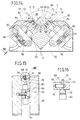
- Figure 14, 15 and 16 show an another variant of the device according to the invention. Elements corresponding to those described above are indicated by the same reference numerals.
- This device includes a base 60.
- the base 60 is formed approximately in a shape of rectangular block and has a V-shaped groove 62 defined by two groove surface 68 on the top portion of the base 60; the V-shaped groove 62 receives the folded piece 2.
- the base 60 has a gap 64 which opens mainly toward the bottom surface thereof.
- the base 60 further has a pair of portion 66 at a suitable position of the top portion thereof.
- Each portion 66 is provided with a hole 70 that communicate from the gap 64 to the groove 62.
- a pair of feelers 72 are provided in the holes 70 respectively.
- the each feeler 72 is movably disposed within a plane perpendicular to the vertex of the V-shaped groove 62.
- the each feeler 72 is formed in a shape of a rectangular plate and has a active surface 73 so as to be in contact with the piece 2.
- the each feeler has a longitudinal slot 74.
- a pin 76 is inserted in the longitudinal slot 74, and the both ends of the pin 76 are fixed to the inside wall of the hole 70.
- the feeler 72 has a bottom portion 78. In this configuration, the feeler 72 is movable in the direction perpendicular to the groove surface 68 and rotatable about the pin 76.
- a pair of distance measuring sensors 84 for each feeler 72 are fixed to the base 60 by the bracket 86.
- a rod 80 is inserted in each distance-measuring sensor 84.
- the each rod 80 is pushed against right and left end of the bottom portion 78 of the feeler 72 by a spring 82.
- the each rod 80 is extended in the direction which is perpendicular to the groove surface 68 and is within the plane perpendicular to the vertex of the V-shaped groove 62.
- the distance-measuring sensors 84 can measure the position of the rod 80 with respect to the distance-measuring sensors 84. In this configuration, when the piece 2 folded by the punch 4 and die 6 comes into contact with the each feeler 72, the pair of rods 80 are retracted into the sensors 84 respectively. Each position of the rod is then measured by the sensor 84 and the bend angle C is calculated by the control unit.
- the pair of feelers 72 are movable and rotatable independently within the plane perpendicular to the vertex of the V-shaped groove 62, and therefore the active surface 73 of the feelers 72 can adapt precisely to the surface of the pieces 2. Accordingly this device can measure the bend angle C precisely. Further, this device has the feelers 72 each of which has large active surface 73. Therefore the determination of the bending angle C is not affected by surface roughness of the piece 2. Moreover the feelers 72 are provided on the base 60 rather than on the die.
- the bend angle C can be precisely measured by means of the active surfaces 73, even if the V-shaped groove 14 of the die 6 is very small; this is because the lateral width of the active surface 73 could be longer than the width of the V-shaped groove 14 of the die 6. Consequently this device can measure the bent angle C precisely.
- FIG. 17A, 17B and 17C Another enbodymennt of this invention shown in Figures 17A, 17B and 17C provides for the use of two feelers 110 having large contact surfaces which are urged resiliently against respective portions of the bent-metal dihedron 112.
- the feelers 110 are articulated about the same shaft 114 which is carried by a base 116 movable perpendicular to the bending line. Means 118 are associated with the two feelers for measuring the angle formed between them.
- the feelers are associated with respective springs 120 which impart to the feelers 110 forces which make them pivot about their common articulation axis 114 in order to close them against the facing surfaces of the sheet-metal dihedron 112.
- the base 116 on which the feelers 110 are articulated is associated with an actuator 122 which urges the base 116 towards the vertex of the piece in a direction perpendicular to the bending line.
Landscapes
- Physics & Mathematics (AREA)
- General Physics & Mathematics (AREA)
- Engineering & Computer Science (AREA)
- Mechanical Engineering (AREA)
- Bending Of Plates, Rods, And Pipes (AREA)
- Length Measuring Devices With Unspecified Measuring Means (AREA)
- A Measuring Device Byusing Mechanical Method (AREA)
- Constituent Portions Of Griding Lathes, Driving, Sensing And Control (AREA)
- Machine Tool Sensing Apparatuses (AREA)
- Electrical Discharge Machining, Electrochemical Machining, And Combined Machining (AREA)
- Measurement Of Length, Angles, Or The Like Using Electric Or Magnetic Means (AREA)
Claims (20)
- Eine Vorrichtung zum Messen eines Winkels in einem Werkstück mit:dadurch gekennzeichnet, daßeinem Grundkörper (8,60);Fühlern (12,72), die relativ zu dem Grundkörper (8,60) bewegbar sind, und wobei jeder der Fühler Kontakteinrichtungen (16,73) zum Kontakt mit einem jeweiligen Abschnitt (2a,2b) des Werkstücks (2) während der Messung aufweist, die Fühler (12,72) sind voneinander kinematisch vollständig unabhängig;Druckeinrichtungen (18,82), um die Kontakteinrichtungen (16,73) der Fühler (12,72) in Kontakt mit den jeweiligen Abschnitten (2a,2b) des Werkstücks (2), das vermessen wird, zu bringen, wobei die Druckeinrichtungen (18,82), die einem Fühler (12,72) zugeordnet sind, vollständig unabhängig von den Druckeinrichtungen (18,82) sind, die dem anderen Fühler (12,72) zugeordnet sind und es dem jeweiligen Fühler (12,72) erlauben, eine translatorische Bewegung relativ zu dem Grundkörper (8,60) vollständig unabhängig von der Bewegung des anderen Fühlers (12,72) auszuführen; und einerSensoreinrichtung (32,84) zur Erfassung der Positionen der Fühler (12,72) relativ zu dem Grundkörper (8,60),jeder Fühler (12,72) eine aktive Oberfläche für den Kontakt mit dem jeweiligen Abschnitt (2a,2b) des Werkstücks (2) aufweist und die Sensoreinrichtung (32,84) ein Paar von Abstandsmeßelementen aufweist, die unter einem bekannten Abstand voneinander beabstandet sind und in einer Ebene des zu messenden Winkels liegen, wobei die Meßelemente mit zwei unterschiedlichen Punkten mit dem bewegbaren Fühler (12,72) verbunden sind, wobei ein Paar dieser Fühler (12,72) und die verbundenen Meßelemente innerhalb des Grundkörpers (8,60) angeordnet sind.
- Die Vorrichtung gemäß Anspruch 1, wobei die Fühler (12,72) frei sind, um eine translatorische und eine rotatorische Bewegung unabhängig voneinander innerhalb einer Ebene, die senkrecht zu einem Scheitelpunkt des zu messenden Winkels ist, auszuführen.
- Die Vorrichtung gemäß Anspruch 2, wobei jeder der Fühler (12) allein durch elastische Elemente (18), die die Druckeinrichtung bilden, mit dem Grundkörper (8) verbunden ist.
- Die Vorrichtung gemäß Anspruch 1, wobei die Fühler (12) einstückig mit dem Grundkörper (8) ausgebildet sind und die Druckeinrichtungen durch einstückige Verbindungseinrichtungen (18) gebildet sind, die zwischen den Fühlern (12) und dem Grundkörper (8) angerodnet und so hergestellt sind, daß sie sehr flexibel in eine Richtung senkrecht zu den aktiven Oberflächen (16) der jeweiligen Fühler (12) sind.
- Die Vorrichtung gemäß Anspruch 4, wobei jeder Fühler (12) eine H-förmige Ausbildung aufweist mit einem zentralen Steg (24), der zwei parallele Abschnitte (20,22) miteinander verbindet, zwischen denen sich zwei dünne Streifen (18), die einstückige Verbindungselemente bilden, die sich zwischen dem Fühler (12) und dem Grundkörper (8) erstrecken.
- Die Vorrichtung gemäß Anspruch 5, wobei sich die Streifen in einer mehrfach S-förmigen Struktur erstrecken.
- Die Vorrichtung gemäß Anspruch 4, wobei die Fühler (12) und die einstückigen Verbindungselemente (18) durch das Entfernen von Material aus einem Bereich (26), das ergänzend zu einem geschlossenen Bereich ist, der die Fühler (12) und die einstükkigen Verbindungselemente (18) bestimmt, ausgebildet sind.
- Die Vorrichtung gemäß Anspruch 1, wobei die Sensoreinrichtung für jeden bewegbaren Fühler (12) ein Paar von im wesentlichen parallelen Abstandmeßelementen (32) aufweist.
- Die Vorrichtung gemäß Anspruch 1, wobei der Grundkörper (8) relativ zu dem Werkstück (2) bewegbar ist und durch eine Betätigungseinrichtung (44) zum Werkstück (2) gedrückt wird, wobei der Grundkörper eine Stützeinrichtung (48) aufweist, um eine stabile Position zur Ausführung der Messung zu bestimmen, in der der Grundkörper (8) in einer fixierten Position relativ zu dem Werkstück (2) durch die Tätigkeit der Betätigungseinrichtung gehalten wird.
- Die Vorrichtung gemäß Anspruch 9, wobei die Betätigungseinrichtung zumindest ein elastisches Element (44) aufweist, das den Grundkörper (8) gedrückt gegen das Werkstück (2) mit einer Kraft halten kann, die wesentlich größer ist als die Kraft, mit der die Druckeinrichtungen (18) die Fühler (12) in Kontakt mit den jeweiligen Abschnitten (2a,2b) des Werkstück (2) halten.
- Die Vorrichtung gemäß Anspruch 1, mit außerdem einem Kalibrierelement, das zwei Referenzflächen zur Zusammenarbeit mit den Fühlern (12) aufweist, wobei die Referenzflächen unter einem Referenzwinkel gegeneinander geneigt sind, der mit einer gleichen oder besseren Genauigkeit als die, mit der die Messung ausgeführt wird, bekannt ist.
- Die Vorrichtung gemäß Anspruch 1 zum Messen des Winkels (C), der in einem Werkstück aus Plattenmaterial (2) durch Biegen gebildet ist, während eines Vorgangs des Biegens des Werkstücks (2) in einer Biegepresse, die einen Stempel (4), der mit einem Gesenk (6), das eine V-förmige Rinne (14) aufweist, zusammenarbeitet, wobei der Grundkörper (8) in einem Schlitz (13) in dem Gesenk (6) montiert ist, so daß eine Symmetrieebene der V-förmigen Rinne (14) in dem Gesenk (6) im wesentlichen mit einer Symmetrieebene einer V-förmigen Rinne (46) in einem Körper (11) der Meßvorrichtung (1) übereinstimmt.
- Die Vorrichtung gemäß Anspruch 9 zum Messen des Winkels (C), der in einem Werkstück aus Plattenmaterial (2) durch Biegen gebildet ist während eines Vorgangs des Biegens des Werkstücks (2) in einer Biegepresse, die einen Stempel (4), der mit einem Gesenk (6), das eine V-förmige Rinne (14) aufweist, zusammenarbeitet, wobei der Grundkörper (8) in einem Schlitz (13) in dem Gesenk (6) montiert ist, so daß eine Symmetrieebene der V-förmigen Rinne (14) in dem Gesenk (6) im wesentlichen mit einer Symmetrieebene einer V-förmigen Rinne (46) in einem Körper (11) der Meßvorrichtung (1) übereinstimmt und Seiten der V-förmigen Rinne (46) in dem Körper (11) im wesentlichen größer sind als Seiten der V-förmigen Rinne (14) in dem Gesenk (6).
- Die Vorrichtung gemäß Anspruch 12 oder 13 umfaßt, mit außerdem einer Sensoreinrichtung (32) zur Erzeugung elektrischer Signale, die den gemessenen Winkel entsprechen und zur Übertragung von Signalen zu einer Steuereinheit (38) dienen, wobei die Steuereinheit (38) zur Steuerung einer Betätigungseinrichtung (40), die die relative Bewegung des Stempels (4) und des Gesenks (6) zueinander aufbringt, verwendbar ist.
- Die Vorrichtung gemäß Anspruch 14, wobei die Steuereinheit (38) angeordnet ist zur Ausführung des Biegevorgangs in aufeinanderfolgenden Schritten, in denen der relative Abstand zwischen dem Stempel (4) und dem Gesenk (6) in jedem Biegeschritt im Vergleich mit dem vorhergehenden Schritt progressiv abnimmt, beginnend von einem Startwert, der einem Biegewinkel größer als der gewünschte Wert entspricht, wobei die verschiedenen Biegeschritte mit Messungen des Winkels (C) abwechseln.
- Die Vorrichtung gemäß Anspruch 1, mit außerdem einer Vorrichtung zur Anzeige des Wertes des gemessenen Winkels auf.
- Die Vorrichtung gemäß Anspruch 2, mit außerdem Stäben (80), die in Kontakt mit dem Fühler (72) sind, wobei die Druckeinrichtungen elastische Einrichtungen (82) sind, die die Stäbe (80) auf den Fühler (72) drücken und die Sensoreinrichtungen Abstandmeßsensoren (84) sind, die eine Position der Stäbe (80) mit Bezug auf die Abstandmeßsensorungen messen können.
- Die Vorrichtung gemäß Anspruch 17, wobei der Grundkörper (60) Löcher (70) aufweist, in denen die Fühler (72) bewegbar und drehbar eingesetzt sind.
- Die Vorrichtung gemäß Anspruch 18, wobei jeder der Fühler (72) einen längserstreckenden Schlitz (74) aufweist, wobei der Grundkörper mit Stiften (76) in den Löchern (70) versehen ist, und jeder Stift (76) in dem längserstreckenden Schlitz (74) eingesetzt ist.
- Die Vorrichtung gemäß Anspruch 17, wobei die Abstandsmeßeinrichtungen (84) zylinderförmig ausgebildet sind und die Stäbe (80) bewegbar darin aufnehmen.
Applications Claiming Priority (3)
| Application Number | Priority Date | Filing Date | Title |
|---|---|---|---|
| ITTO930117 | 1993-02-23 | ||
| ITTO930117A IT1260892B (it) | 1993-02-23 | 1993-02-23 | Dispositivo per misurare l'angolo di un pezzo, in particolare l'angolodi piegatura di un pezzo di lamiera. |
| PCT/JP1994/000257 WO1994019662A1 (en) | 1993-02-23 | 1994-02-21 | A device for measuring an angle in a piece |
Publications (2)
| Publication Number | Publication Date |
|---|---|
| EP0637371A1 EP0637371A1 (de) | 1995-02-08 |
| EP0637371B1 true EP0637371B1 (de) | 1998-07-22 |
Family
ID=11411164
Family Applications (1)
| Application Number | Title | Priority Date | Filing Date |
|---|---|---|---|
| EP94907078A Expired - Lifetime EP0637371B1 (de) | 1993-02-23 | 1994-02-21 | Vorrichtung zum messen des winkels eines werkstückes |
Country Status (8)
| Country | Link |
|---|---|
| US (1) | US5584199A (de) |
| EP (1) | EP0637371B1 (de) |
| JP (1) | JP3110761B2 (de) |
| KR (1) | KR100321220B1 (de) |
| AT (1) | ATE168770T1 (de) |
| DE (1) | DE69411821T2 (de) |
| IT (1) | IT1260892B (de) |
| WO (1) | WO1994019662A1 (de) |
Cited By (1)
| Publication number | Priority date | Publication date | Assignee | Title |
|---|---|---|---|---|
| WO2013188896A1 (de) | 2012-06-18 | 2013-12-27 | Trumpf Maschinen Austria Gmbh & Co. Kg. | Biegepresse mit winkelerfassungsvorrichtung sowie verfahren zur ermittlung des biegewinkels |
Families Citing this family (21)
| Publication number | Priority date | Publication date | Assignee | Title |
|---|---|---|---|---|
| ES2172009T3 (es) * | 1997-06-20 | 2002-09-16 | Luciano Gasparini | Prensa plegadora de hoja metalica. |
| IT1311827B1 (it) * | 1999-04-16 | 2002-03-19 | Luciano Gasparini | Forchetta a forcella del tipo basculante autocentrante,particolarmente per la misurazione su quattro punti dell'angolo di |
| EP1083403A1 (de) * | 1999-09-08 | 2001-03-14 | Bystronic Laser AG | Verfahren sowie Anordnung zum Ermitteln des Biegewinkels von Werkstücken |
| KR100519521B1 (ko) * | 1999-10-07 | 2005-10-05 | 무라타 기카이 가부시키가이샤 | 굽힘기계 및 그 운전방법 |
| CN1262366C (zh) * | 2000-08-11 | 2006-07-05 | 株式会社阿玛达 | 弯曲设备 |
| JP4637396B2 (ja) * | 2001-04-12 | 2011-02-23 | 株式会社アミテック | 角度測定器 |
| US20030121303A1 (en) * | 2001-12-28 | 2003-07-03 | Lanni Arthur L. | Die set with position sensor mounted thereon |
| JP2006205256A (ja) | 2004-12-27 | 2006-08-10 | Amada Co Ltd | ワークの曲げ角度検出装置およびワークの曲げ加工機 |
| DE102006050687B4 (de) * | 2006-10-24 | 2010-01-28 | Hans Schröder Maschinenbau GmbH | Verfahren zur Messung und/oder Korrektur der Werkstückform nach dem Umformen durch Biegen |
| JP5125275B2 (ja) | 2007-02-05 | 2013-01-23 | トヨタ自動車株式会社 | 燃料電池および燃料電池搭載車両 |
| AR080194A1 (es) | 2010-02-17 | 2012-03-21 | Dsm Ip Assets Bv | Composiciones antimicrobianas liquidas |
| CN102120230B (zh) * | 2010-12-03 | 2012-12-05 | 中联重科股份有限公司 | 一种弯折件的弯折角度测量设备及方法 |
| JP5883627B2 (ja) * | 2011-12-02 | 2016-03-15 | 株式会社アマダホールディングス | 板材曲げ加工装置用曲げ角度検出装置 |
| AT513279B1 (de) * | 2012-11-08 | 2014-03-15 | Trumpf Maschinen Austria Gmbh | Messeinrichtung und Messverfahren zum Messen der Dicke eines plattenförmigen Gegenstands sowie Biegemaschine |
| AT515279B1 (de) * | 2014-06-12 | 2015-08-15 | Trumpf Maschinen Austria Gmbh | Kalibrierwerkzeug für ein Winkelmesswerkzeug in einem Biegestempel und Verfahren zum Kalibrieren des Winkelmesswerkzeuges |
| DE102014225169A1 (de) * | 2014-12-08 | 2016-06-09 | Robert Bosch Gmbh | Pneumatischer Messdorn und Messsystem |
| JP6537915B2 (ja) * | 2015-07-27 | 2019-07-03 | Ntn株式会社 | ピッチ円錐角測定方法及び測定装置 |
| ES2938914T3 (es) * | 2017-11-14 | 2023-04-17 | Hexagon Technology As | Sistema de montaje de sensores |
| AT521529B1 (de) * | 2018-07-27 | 2020-04-15 | Trumpf Maschinen Austria Gmbh & Co Kg | Biegevorrichtung und Verfahren zur Ermittlung zumindest eines Materialparameters bzw. Bearbeitungsparameters für eine Werkstückbearbeitungsvorrichtung |
| KR102062619B1 (ko) * | 2019-07-22 | 2020-01-06 | 금강메탈 주식회사 | 자동차부품 성형용 단조금형 제작장치 |
| KR102167710B1 (ko) * | 2019-10-23 | 2020-10-19 | 장춘기 | 자동차부품 성형용 단조금형 제작장치 |
Family Cites Families (13)
| Publication number | Priority date | Publication date | Assignee | Title |
|---|---|---|---|---|
| FR1425315A (fr) * | 1964-10-14 | 1966-01-24 | Promecan Sisson Lehmann | Perfectionnements aux outils de pliage |
| DE2044199C3 (de) * | 1970-09-07 | 1974-12-05 | Karl Mengele & Soehne Maschinenfabrik Und Eisengiesserei Guenzburg-Donau, 8870 Guenzburg | Winkelmeß- und Steuereinrichtung an Biege- insbesondere Freibiegemaschinen |
| FR2362722A1 (fr) * | 1976-08-27 | 1978-03-24 | Promecan Sisson Lehmann | Dispositif de controle de l'angle de pliage d'une tole ou similaire sur une presse plieuse |
| IT1072273B (it) * | 1977-02-01 | 1985-04-10 | Selecontrol Sas | Dispositivo per la rilevazione e regolazione di angoli di piega particolarmente adatto per presse-piegatrici |
| DE3008701A1 (de) * | 1980-03-07 | 1981-09-24 | Johann 7057 Leutenbach Hess | Winkelmessvorrichtung fuer abkantpressen |
| JPS5982119A (ja) * | 1982-11-01 | 1984-05-12 | Komatsu Ltd | 折曲げ機の曲げ角度検出装置 |
| US4864509A (en) * | 1987-09-29 | 1989-09-05 | The Boeing Company | Method and related apparatus for controlling the operation of a press brake |
| DE3739173A1 (de) * | 1987-11-19 | 1989-06-01 | Feintool Int Holding | Verfahren und vorrichtung zum biegen von werkstuecken |
| US5062283A (en) * | 1988-07-19 | 1991-11-05 | Yamazaki Mazak Kabushiki Kaisha | Press brake and a workpiece measuring method in the press brake |
| US5148693A (en) * | 1989-11-14 | 1992-09-22 | Amada Company, Limited | Method and a device for detecting folding angles of a metal sheet during the folding and a method for folding of a metal sheet |
| SE505985C2 (sv) * | 1989-11-14 | 1997-10-27 | Amada Co Ltd | Sätt och anordning för avkänning av bockningsvinklar för en metallplåt under bockningen |
| CH689613A5 (fr) * | 1992-10-20 | 1999-07-15 | Beyeler Machines Sa | Dispositif de mesure de l'angle de pliage d'une tôle dans une presse. |
| JP2630720B2 (ja) * | 1992-11-06 | 1997-07-16 | 丸機械工業株式会社 | 板材の折曲げ角検出装置及びこれを使用したプレス機械の運転方法 |
-
1993
- 1993-02-23 IT ITTO930117A patent/IT1260892B/it active IP Right Grant
-
1994
- 1994-02-21 DE DE69411821T patent/DE69411821T2/de not_active Expired - Fee Related
- 1994-02-21 US US08/325,330 patent/US5584199A/en not_active Expired - Lifetime
- 1994-02-21 JP JP06518822A patent/JP3110761B2/ja not_active Expired - Fee Related
- 1994-02-21 EP EP94907078A patent/EP0637371B1/de not_active Expired - Lifetime
- 1994-02-21 WO PCT/JP1994/000257 patent/WO1994019662A1/en not_active Ceased
- 1994-02-21 KR KR1019940703825A patent/KR100321220B1/ko not_active Expired - Fee Related
- 1994-02-21 AT AT94907078T patent/ATE168770T1/de not_active IP Right Cessation
Cited By (2)
| Publication number | Priority date | Publication date | Assignee | Title |
|---|---|---|---|---|
| WO2013188896A1 (de) | 2012-06-18 | 2013-12-27 | Trumpf Maschinen Austria Gmbh & Co. Kg. | Biegepresse mit winkelerfassungsvorrichtung sowie verfahren zur ermittlung des biegewinkels |
| US9664493B2 (en) | 2012-06-18 | 2017-05-30 | Trumpf Maschinen Austria Gmbh & Co. Kg. | Bending press having an angle-measuring device and method for determining the bending angle |
Also Published As
| Publication number | Publication date |
|---|---|
| ATE168770T1 (de) | 1998-08-15 |
| DE69411821D1 (de) | 1998-08-27 |
| KR950701424A (ko) | 1995-03-23 |
| IT1260892B (it) | 1996-04-29 |
| ITTO930117A1 (it) | 1994-08-23 |
| DE69411821T2 (de) | 1998-12-03 |
| EP0637371A1 (de) | 1995-02-08 |
| ITTO930117A0 (it) | 1993-02-23 |
| JP3110761B2 (ja) | 2000-11-20 |
| JPH07506194A (ja) | 1995-07-06 |
| US5584199A (en) | 1996-12-17 |
| WO1994019662A1 (en) | 1994-09-01 |
| KR100321220B1 (ko) | 2002-07-02 |
Similar Documents
| Publication | Publication Date | Title |
|---|---|---|
| EP0637371B1 (de) | Vorrichtung zum messen des winkels eines werkstückes | |
| US4802357A (en) | Apparatus and method of compensating for springback in a workpiece | |
| CA1174043A (en) | Device for measuring the fold angle in a sheet metal bending press | |
| US4936126A (en) | Press brake with a displacement sensor of electric signal output | |
| US4131008A (en) | Device for measuring the bending angles in plate-bending machines | |
| JPH10503972A (ja) | 工作物を折り曲げるための方法及び加工機械 | |
| CZ9904634A3 (cs) | Ohýbací lis | |
| US20030015011A1 (en) | Sheet working method, sheet working system, and various devices related to such system | |
| JPH0318499A (ja) | 寸法の安定したプレス品を製造する方法および装置 | |
| US5806201A (en) | Multi-coordinate touch probe | |
| US5224274A (en) | Contact gage | |
| US4813152A (en) | Clearance gauge for setting a tool above a workpiece | |
| BE1007424A5 (nl) | Adaptief plooien. | |
| CN100528395C (zh) | 工件的弯曲角度检测装置及工件的弯曲加工机 | |
| KR0151993B1 (ko) | 두께 측정장치 및 이를 이용한 두께 측정방법 | |
| GB1483798A (en) | Method and apparatus for the indirect measurement of the longitudinal development of curved seats or grooves in mechanical workpieces | |
| KR102120322B1 (ko) | 틸팅 구동되는 길이측정용 접촉식 프로브 구조 | |
| JP2000233229A (ja) | バックゲージ装置におけるl軸補正方法およびバックゲージ装置並びにこのl軸補正方法に用いる基準治具 | |
| JP2004042136A (ja) | 部品検査矯正方法及び部品検査矯正装置 | |
| JP2501694Y2 (ja) | 溝の加工精度測定装置 | |
| JPH0526481Y2 (de) | ||
| US5904058A (en) | Decamberer | |
| JPH0650702A (ja) | 内外径測定装置 | |
| JPH0416166Y2 (de) | ||
| JPH11104740A (ja) | 板材曲げ加工機における金型の取付位置誤差の検出方法およびその装置並びにバックゲージ突当の原点自動設定方法およびその装置 |
Legal Events
| Date | Code | Title | Description |
|---|---|---|---|
| PUAI | Public reference made under article 153(3) epc to a published international application that has entered the european phase |
Free format text: ORIGINAL CODE: 0009012 |
|
| 17P | Request for examination filed |
Effective date: 19941021 |
|
| AK | Designated contracting states |
Kind code of ref document: A1 Designated state(s): AT CH DE FR GB LI SE |
|
| 17Q | First examination report despatched |
Effective date: 19961014 |
|
| GRAG | Despatch of communication of intention to grant |
Free format text: ORIGINAL CODE: EPIDOS AGRA |
|
| GRAG | Despatch of communication of intention to grant |
Free format text: ORIGINAL CODE: EPIDOS AGRA |
|
| GRAG | Despatch of communication of intention to grant |
Free format text: ORIGINAL CODE: EPIDOS AGRA |
|
| GRAH | Despatch of communication of intention to grant a patent |
Free format text: ORIGINAL CODE: EPIDOS IGRA |
|
| GRAH | Despatch of communication of intention to grant a patent |
Free format text: ORIGINAL CODE: EPIDOS IGRA |
|
| GRAA | (expected) grant |
Free format text: ORIGINAL CODE: 0009210 |
|
| AK | Designated contracting states |
Kind code of ref document: B1 Designated state(s): AT CH DE FR GB LI SE |
|
| REF | Corresponds to: |
Ref document number: 168770 Country of ref document: AT Date of ref document: 19980815 Kind code of ref document: T |
|
| REG | Reference to a national code |
Ref country code: CH Ref legal event code: NV Representative=s name: ISLER & PEDRAZZINI AG Ref country code: CH Ref legal event code: EP |
|
| REF | Corresponds to: |
Ref document number: 69411821 Country of ref document: DE Date of ref document: 19980827 |
|
| ET | Fr: translation filed | ||
| PLBE | No opposition filed within time limit |
Free format text: ORIGINAL CODE: 0009261 |
|
| STAA | Information on the status of an ep patent application or granted ep patent |
Free format text: STATUS: NO OPPOSITION FILED WITHIN TIME LIMIT |
|
| 26N | No opposition filed | ||
| REG | Reference to a national code |
Ref country code: GB Ref legal event code: IF02 |
|
| PGFP | Annual fee paid to national office [announced via postgrant information from national office to epo] |
Ref country code: AT Payment date: 20030221 Year of fee payment: 10 |
|
| PGFP | Annual fee paid to national office [announced via postgrant information from national office to epo] |
Ref country code: SE Payment date: 20030224 Year of fee payment: 10 |
|
| PG25 | Lapsed in a contracting state [announced via postgrant information from national office to epo] |
Ref country code: AT Free format text: LAPSE BECAUSE OF NON-PAYMENT OF DUE FEES Effective date: 20040221 |
|
| PG25 | Lapsed in a contracting state [announced via postgrant information from national office to epo] |
Ref country code: SE Free format text: LAPSE BECAUSE OF NON-PAYMENT OF DUE FEES Effective date: 20040222 |
|
| EUG | Se: european patent has lapsed | ||
| PGFP | Annual fee paid to national office [announced via postgrant information from national office to epo] |
Ref country code: CH Payment date: 20060220 Year of fee payment: 13 |
|
| PG25 | Lapsed in a contracting state [announced via postgrant information from national office to epo] |
Ref country code: LI Free format text: LAPSE BECAUSE OF NON-PAYMENT OF DUE FEES Effective date: 20070228 Ref country code: CH Free format text: LAPSE BECAUSE OF NON-PAYMENT OF DUE FEES Effective date: 20070228 |
|
| REG | Reference to a national code |
Ref country code: CH Ref legal event code: PCAR Free format text: ISLER & PEDRAZZINI AG;POSTFACH 1772;8027 ZUERICH (CH) |
|
| REG | Reference to a national code |
Ref country code: CH Ref legal event code: PL |
|
| PGFP | Annual fee paid to national office [announced via postgrant information from national office to epo] |
Ref country code: GB Payment date: 20090223 Year of fee payment: 16 |
|
| PGFP | Annual fee paid to national office [announced via postgrant information from national office to epo] |
Ref country code: DE Payment date: 20090327 Year of fee payment: 16 |
|
| PGFP | Annual fee paid to national office [announced via postgrant information from national office to epo] |
Ref country code: FR Payment date: 20090219 Year of fee payment: 16 |
|
| GBPC | Gb: european patent ceased through non-payment of renewal fee |
Effective date: 20100221 |
|
| REG | Reference to a national code |
Ref country code: FR Ref legal event code: ST Effective date: 20101029 |
|
| PG25 | Lapsed in a contracting state [announced via postgrant information from national office to epo] |
Ref country code: FR Free format text: LAPSE BECAUSE OF NON-PAYMENT OF DUE FEES Effective date: 20100301 |
|
| PG25 | Lapsed in a contracting state [announced via postgrant information from national office to epo] |
Ref country code: DE Free format text: LAPSE BECAUSE OF NON-PAYMENT OF DUE FEES Effective date: 20100901 |
|
| PG25 | Lapsed in a contracting state [announced via postgrant information from national office to epo] |
Ref country code: GB Free format text: LAPSE BECAUSE OF NON-PAYMENT OF DUE FEES Effective date: 20100221 |