EP0637497A1 - Soudeuse pour matières thermoplastiques - Google Patents
Soudeuse pour matières thermoplastiques Download PDFInfo
- Publication number
- EP0637497A1 EP0637497A1 EP94106289A EP94106289A EP0637497A1 EP 0637497 A1 EP0637497 A1 EP 0637497A1 EP 94106289 A EP94106289 A EP 94106289A EP 94106289 A EP94106289 A EP 94106289A EP 0637497 A1 EP0637497 A1 EP 0637497A1
- Authority
- EP
- European Patent Office
- Prior art keywords
- knife
- rotation
- conveyor
- conveying
- welding device
- Prior art date
- Legal status (The legal status is an assumption and is not a legal conclusion. Google has not performed a legal analysis and makes no representation as to the accuracy of the status listed.)
- Granted
Links
- 239000012815 thermoplastic material Substances 0.000 title abstract 2
- 238000005520 cutting process Methods 0.000 claims abstract description 25
- 239000004033 plastic Substances 0.000 claims description 41
- 238000004023 plastic welding Methods 0.000 claims description 27
- 239000000463 material Substances 0.000 claims description 10
- 230000033001 locomotion Effects 0.000 claims description 2
- 229920000642 polymer Polymers 0.000 abstract 1
- 239000002861 polymer material Substances 0.000 abstract 1
- 238000003466 welding Methods 0.000 description 6
- 238000010438 heat treatment Methods 0.000 description 3
- 210000003746 feather Anatomy 0.000 description 2
- 238000000034 method Methods 0.000 description 2
- 230000008878 coupling Effects 0.000 description 1
- 238000010168 coupling process Methods 0.000 description 1
- 238000005859 coupling reaction Methods 0.000 description 1
- 230000000694 effects Effects 0.000 description 1
- 238000005516 engineering process Methods 0.000 description 1
- 238000002474 experimental method Methods 0.000 description 1
- 230000010006 flight Effects 0.000 description 1
- 238000004519 manufacturing process Methods 0.000 description 1
- 239000002985 plastic film Substances 0.000 description 1
- 238000000926 separation method Methods 0.000 description 1
Images


Classifications
-
- B—PERFORMING OPERATIONS; TRANSPORTING
- B29—WORKING OF PLASTICS; WORKING OF SUBSTANCES IN A PLASTIC STATE IN GENERAL
- B29C—SHAPING OR JOINING OF PLASTICS; SHAPING OF MATERIAL IN A PLASTIC STATE, NOT OTHERWISE PROVIDED FOR; AFTER-TREATMENT OF THE SHAPED PRODUCTS, e.g. REPAIRING
- B29C65/00—Joining or sealing of preformed parts, e.g. welding of plastics materials; Apparatus therefor
- B29C65/02—Joining or sealing of preformed parts, e.g. welding of plastics materials; Apparatus therefor by heating, with or without pressure
- B29C65/40—Applying molten plastics, e.g. hot melt
-
- B—PERFORMING OPERATIONS; TRANSPORTING
- B26—HAND CUTTING TOOLS; CUTTING; SEVERING
- B26D—CUTTING; DETAILS COMMON TO MACHINES FOR PERFORATING, PUNCHING, CUTTING-OUT, STAMPING-OUT OR SEVERING
- B26D1/00—Cutting through work characterised by the nature or movement of the cutting member or particular materials not otherwise provided for; Apparatus or machines therefor; Cutting members therefor
- B26D1/0006—Cutting members therefor
-
- B—PERFORMING OPERATIONS; TRANSPORTING
- B29—WORKING OF PLASTICS; WORKING OF SUBSTANCES IN A PLASTIC STATE IN GENERAL
- B29C—SHAPING OR JOINING OF PLASTICS; SHAPING OF MATERIAL IN A PLASTIC STATE, NOT OTHERWISE PROVIDED FOR; AFTER-TREATMENT OF THE SHAPED PRODUCTS, e.g. REPAIRING
- B29C48/00—Extrusion moulding, i.e. expressing the moulding material through a die or nozzle which imparts the desired form; Apparatus therefor
- B29C48/02—Small extruding apparatus, e.g. handheld, toy or laboratory extruders
-
- B—PERFORMING OPERATIONS; TRANSPORTING
- B29—WORKING OF PLASTICS; WORKING OF SUBSTANCES IN A PLASTIC STATE IN GENERAL
- B29C—SHAPING OR JOINING OF PLASTICS; SHAPING OF MATERIAL IN A PLASTIC STATE, NOT OTHERWISE PROVIDED FOR; AFTER-TREATMENT OF THE SHAPED PRODUCTS, e.g. REPAIRING
- B29C48/00—Extrusion moulding, i.e. expressing the moulding material through a die or nozzle which imparts the desired form; Apparatus therefor
- B29C48/25—Component parts, details or accessories; Auxiliary operations
- B29C48/285—Feeding the extrusion material to the extruder
- B29C48/288—Feeding the extrusion material to the extruder in solid form, e.g. powder or granules
- B29C48/2888—Feeding the extrusion material to the extruder in solid form, e.g. powder or granules in thread form or in strip form, e.g. rubber strips
-
- B—PERFORMING OPERATIONS; TRANSPORTING
- B29—WORKING OF PLASTICS; WORKING OF SUBSTANCES IN A PLASTIC STATE IN GENERAL
- B29C—SHAPING OR JOINING OF PLASTICS; SHAPING OF MATERIAL IN A PLASTIC STATE, NOT OTHERWISE PROVIDED FOR; AFTER-TREATMENT OF THE SHAPED PRODUCTS, e.g. REPAIRING
- B29C66/00—General aspects of processes or apparatus for joining preformed parts
- B29C66/80—General aspects of machine operations or constructions and parts thereof
- B29C66/84—Specific machine types or machines suitable for specific applications
- B29C66/861—Hand-held tools
-
- B—PERFORMING OPERATIONS; TRANSPORTING
- B26—HAND CUTTING TOOLS; CUTTING; SEVERING
- B26D—CUTTING; DETAILS COMMON TO MACHINES FOR PERFORATING, PUNCHING, CUTTING-OUT, STAMPING-OUT OR SEVERING
- B26D1/00—Cutting through work characterised by the nature or movement of the cutting member or particular materials not otherwise provided for; Apparatus or machines therefor; Cutting members therefor
- B26D1/0006—Cutting members therefor
- B26D2001/0033—Cutting members therefor assembled from multiple blades
-
- B—PERFORMING OPERATIONS; TRANSPORTING
- B26—HAND CUTTING TOOLS; CUTTING; SEVERING
- B26D—CUTTING; DETAILS COMMON TO MACHINES FOR PERFORATING, PUNCHING, CUTTING-OUT, STAMPING-OUT OR SEVERING
- B26D1/00—Cutting through work characterised by the nature or movement of the cutting member or particular materials not otherwise provided for; Apparatus or machines therefor; Cutting members therefor
- B26D1/0006—Cutting members therefor
- B26D2001/0046—Cutting members therefor rotating continuously about an axis perpendicular to the edge
-
- B—PERFORMING OPERATIONS; TRANSPORTING
- B26—HAND CUTTING TOOLS; CUTTING; SEVERING
- B26D—CUTTING; DETAILS COMMON TO MACHINES FOR PERFORATING, PUNCHING, CUTTING-OUT, STAMPING-OUT OR SEVERING
- B26D1/00—Cutting through work characterised by the nature or movement of the cutting member or particular materials not otherwise provided for; Apparatus or machines therefor; Cutting members therefor
- B26D1/0006—Cutting members therefor
- B26D2001/006—Cutting members therefor the cutting blade having a special shape, e.g. a special outline, serrations
-
- B—PERFORMING OPERATIONS; TRANSPORTING
- B29—WORKING OF PLASTICS; WORKING OF SUBSTANCES IN A PLASTIC STATE IN GENERAL
- B29C—SHAPING OR JOINING OF PLASTICS; SHAPING OF MATERIAL IN A PLASTIC STATE, NOT OTHERWISE PROVIDED FOR; AFTER-TREATMENT OF THE SHAPED PRODUCTS, e.g. REPAIRING
- B29C2791/00—Shaping characteristics in general
-
- B—PERFORMING OPERATIONS; TRANSPORTING
- B29—WORKING OF PLASTICS; WORKING OF SUBSTANCES IN A PLASTIC STATE IN GENERAL
- B29C—SHAPING OR JOINING OF PLASTICS; SHAPING OF MATERIAL IN A PLASTIC STATE, NOT OTHERWISE PROVIDED FOR; AFTER-TREATMENT OF THE SHAPED PRODUCTS, e.g. REPAIRING
- B29C48/00—Extrusion moulding, i.e. expressing the moulding material through a die or nozzle which imparts the desired form; Apparatus therefor
- B29C48/03—Extrusion moulding, i.e. expressing the moulding material through a die or nozzle which imparts the desired form; Apparatus therefor characterised by the shape of the extruded material at extrusion
Definitions
- the invention relates to a plastic welding device with at least one conveyor channel and a conveyor device assigned to it for a plastic strand, the conveyor channel opening via an opening into a comminution device which has a knife element rotatable about a knife axis of rotation with at least one knife having a cutting edge, and in which Shredding device connect a transport and a plasticizing device for plasticizing and for ejecting the shredded plastic material.
- Such plastic welding devices are used for welding plastic sheets or the like. They essentially consist of a hand drill that serves as a drive and a removable attachment attached to it. In the front attachment, a plastic strand in the form of a plastic wire fed into a conveyor channel - several parallel conveyor channels can also be provided - and a conveyor device are first cut up and then heated in a conveyor device, usually designed as a screw conveyor, and a plasticizing device such that the fragmented plastic material is plastic Condition and is expelled through a mouthpiece as welding material.
- DE-OS 28 23 171 a generic plastic welding device is disclosed.
- the plastic wire is by means of the Conveying device fed to a separate shredding device.
- This comminution device consists of a plurality of knives, which are arranged on the jacket of the screw conveyor in the area on the inlet side and are distributed radially outward and projecting over the circumference. The cutting edges extend parallel to the axis of rotation of the screw conveyor and, when they are rotated - driven by the hand drill - sweep over an opening of the conveying channel in a housing jacket surrounding the comminution device.
- the previously known shredding device causes difficulties in shredding the plastic wire.
- the capacity of the shredding device is necessarily low because there is only one path available for conveying the plastic wire between two knives, which corresponds approximately to the height of the knives.
- the further transport of the shredded plastic material is not sufficiently secured, since the spaces between individual knives have no connection to the screw flights of the transport screw.
- plastic wire is a relatively tough material, when the ends protruding from the opening are knocked off, imperfect separations and canting of the plastic wire occur within the conveying channel, in particular in the region of the opening of the conveying channel. This in turn leads to disruptions in the conveyance of the plastic wire and thus ultimately to the machine downtime, which is particularly important for a welding process that is currently running is disadvantageous.
- DE-OS 28 23 171 a plastic welding device of the type described in DE-OS 28 23 171 has not come onto the market.
- the applicant of DE-OS 28 23 171 has dispensed with the problematic comminution device (DE-PS 32 21 492).
- DE-PS 32 21 492 the plastic wire is routed in pieces to the screw conveyor of the transport device, where it is cut up by the screw itself.
- a conveyor roller which is connected in one piece to the conveyor screw on the input side and has a thread-like profile on its circumference, serves as the conveyor device, with the conveyor channel being guided in a partial section parallel to the axis of rotation of the conveyor roller and open towards it, in such a way that the profile in notch the outer sheath of the plastic wire.
- the proposal has been made in DE-OS 38 25 250 to feed the conveying channel to the conveying device, which is also designed as a profiled conveying roller, in such a way that the plastic wire is at least pre-shredded by the screw-like profiling of the conveying roller.
- the invention is therefore based on the object of designing a plastic welding device in such a way that the output of a homogeneous plasticized strand of plastic is ensured.
- the rotation surface generated by the cutting edge (s) during the rotation of the knife element with its continuation directed towards the knife axis of rotation intersects the knife axis of rotation and that at least one part lying in the region of the opening of the conveying channel or Parts of the rotation surface lying in the region of the openings of the conveying channels are or are designed as counter knives.
- the rotation surface is to be understood as a fictitious surface that is generated from all points of the cutting edge (s) when the knife element is rotated.
- the cutting edge (s) generate a surface of revolution forming a truncated cone by means of a correspondingly inclined arrangement with respect to the knife axis of rotation.
- the surface of rotation is a plane perpendicular to the axis of rotation of the knife, especially since the counter knife or knives are also each formed as planes perpendicular to the axis of rotation of the knife.
- the conveying device has a conveying roller which can be rotated about an axis of rotation of the roller and the conveying channel or conveying channels in the region of the conveying roller in each case run or extend at least over a portion parallel to the axis of rotation of the roller and is open towards the conveying roller or are and that the conveyor roller carries a profile extending into the conveying channel or conveying channels and causing a conveying movement of the plastic strand, for example in the form of at least one helical conveying web or several conveying webs running in multiple courses.
- This known from DE-PS 32 21 492 design of the conveyor allows a particularly compact and slim shape of the plastic welding device.
- the conveying channel or conveying channels merge into a closed section at a distance from the counter knife, which extends to the associated counter knife. This way the plastic strand is in the area enclosed on all sides of the shredding device and therefore guided properly, which results in a clean cut in the shredding device.
- the above-described design can be dispensed with if the cutting edges of the knives are aligned in such a way that they produce an obliquely outwardly directed cutting pressure. In this way it is ensured that even if no closed section is provided, the cutting forces always act against a wall of the conveying channel or conveying channels and a clean cut is thus achieved.
- the solution is technically simpler.
- the knife element is attached to the output end of the conveyor roller. If the transport device has a transport screw that can be rotated about an axis of rotation of the screw, the knife element can also be attached coaxially to the end of the transport screw on the input side.
- the conveying roller and the conveying screw are arranged coaxially to one another and connected to one another in a rotationally fixed manner, the knife element being arranged between the two, in particular clamped.
- Figure (1) partially represents a plastic welding device, namely only the attachment (1) for attachment to a hand drill.
- the attachment (1) has a mounting hole (2) on the right-hand side in this view, into which the drill head of the hand drill can be inserted.
- the receiving bore (2) sits in a multi-step, each cylindrical housing (3).
- the housing (3) has a reduced axial bore (4) following the receiving bore (2), into which a cylindrical insert sleeve (5) is inserted up to an annular shoulder surface (6) which ends the axial bore (4).
- the insert sleeve (5) is fixed in position with the aid of a screw (7) which extends radially through the housing (3) and surrounds the insert sleeve (5).
- the inner surface of the insert sleeve (5) is stepped, i.e. Over the largest area, the inner surface has a larger diameter than in an end area (8) adjacent to the ring shoulder area (6). In the upper area, the insert sleeve (5) runs through an axially extending section of a conveying channel (9).
- the delivery channel (9) bends upward and continues in an inclined bore (2) which penetrates the housing (3).
- a feed roller (11) extends in the insert sleeve (5), the casing of which is surrounded by a screw web (12) which is sawtooth-shaped in cross section.
- the screw web (12) extends to the inner wall of the insert surface (5) and therefore also projects into into the open area of the delivery channel (9).
- the conveyor roller (11) has a bearing section (13) protruding towards the receiving bore (2), which is supported on an axial ball bearing (15) with an annular web (14). This in turn rests on a support ring (16) inserted into the inner wall of the housing (3).
- a drive shaft (17) projects into an axial bore of the conveyor roller (11) and is connected in a rotationally fixed manner to the bearing section (13) of the conveyor roller (11) via a feather key (18).
- the drive shaft (17) has a flange (19), via which it can be connected to the drill head of the hand drill.
- the axial bore (4) in the housing (3) is adjoined by a screw bore (20) narrowed around the ring shoulder surface (6), which is coaxial with the axial bore (4) or the receiving bore (2).
- the screw bore (20) - which is not shown here - merges into a mouthpiece.
- a screw conveyor (21) is arranged in the screw bore (20) and is provided with a screw web (22).
- the screw conveyor (21) has an extension which projects into a bore in the conveyor roller (11) and which has a rotationally fixed connection to the conveyor roller (11) via a feather key (24).
- the transport screw (21) has a support ring web (25) projecting radially outwards.
- a knife element (26) is clamped between the support ring web (25) and the end face of the conveyor roller (11) opposite this.
- the bracing is achieved in that the extension (23) has a threaded bore (27) which is open towards the free end and into which a clamping screw (28) is fitted, the head of which protrudes on an annular web (29) projecting on the inside of the conveyor roller (11) ) supports.
- the knife element (26) has such a radial extent that it covers almost the entire end face of the insert sleeve (5) and in particular the opening of the delivery channel (9).
- the position of the insert sleeve (5) and the axial support of the conveyor roller via the axial ball bearing (15) or the support ring (16) are matched to one another in such a way that the knife element (26) rests approximately on the end face of the insert sleeve (5) there or there is little play between the two.
- the exact design of the knife element (26) results from the figures (2) and (3).
- the knife element (26) has a non-circular central opening (30) with which the knife element (26) sits on a section of the extension (23) adapted to it, so that the two are connected to one another in a rotationally fixed manner.
- the central opening (30) is surrounded by a ring section (31), from which a total of six outward-facing knives - designated by (32) for example - extend.
- the knives (32) each have a cutting edge - designated by (33) for example.
- the cutting edges (33) run radially to the center point or to the knife axis of rotation of the knife element (26).
- the attachment (1) is connected to a hand drill by inserting its drill head into the mounting hole (2) and coupling to the drive shaft (17). Furthermore, a heating device, not shown here, is started, which is attached to the section of the screw bore (20) or the transport screw (21), not shown. A plastic wire is then inserted into the delivery channel (9) via the oblique bore (10).
- the drive shaft (17), the conveyor roller (11), the extension (23) and thus the transport screw (21) and the knife element (26) are set in rotation.
- the direction of rotation is such that the screw web (12) develops a conveying effect in the direction of the screw conveyor (21), i.e. the plastic wire introduced into the conveying channel (9) is transported in the direction of the tubular end section of the conveying channel (9) in that the screw web (12) digs into the sheath of the plastic wire with its tips.
- the plastic wire when it emerges from the conveying channel (9) between two rotating knives (32), is cut cleanly by the knife (32) following in the rotating direction.
- the opening of the delivery channel (9) in the end face of the insert sleeve (5) acts as a counter knife.
- the plastic material which has been dismembered in this way, then passes through an obliquely extending recess (34) in the housing (3) into the region of the transport screw (21) and is then conveyed to the left in the view shown.
- the dismembered parts of the plastic material heat up, the heating in the following heating device, not shown here, being driven to such an extent that the plastic material becomes plastic and converts to a homogeneous, plasticized plastic strand.
- This strand is then continuously ejected from the mouthpiece of the attachment (1) and then forms the welding material for the objects to be welded.
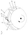
- Figure (4) shows a cross section through another attachment (35) with a view of a knife element (36) in the foreground and an insert sleeve (37) and a conveyor roller (38) in the background.
- the insert sleeve (37) runs downwards open towards the conveyor roller (38), U-shaped delivery channel (39) in which a plastic wire (40) is seated.
- the knife element (36) has radially outwardly protruding knives - designated by way of example with (41) - which have a triangular shape.
- their cutting edges - designated by way of example (42) - do not run radially, but rather obliquely to the radial direction in such a way that the perpendicular to the cutting edges (42) is directed obliquely outwards is.
- a corresponding outward cutting pressure acts on the plastic wire (40) during the cutting process, symbolized by the arrow (A).
- the plastic wire (40) is fully supported in this direction from the inside of the conveyor channel (39).
- the delivery channel (39) need not be designed to be closed at the bottom.
Landscapes
- Engineering & Computer Science (AREA)
- Mechanical Engineering (AREA)
- Life Sciences & Earth Sciences (AREA)
- Forests & Forestry (AREA)
- Health & Medical Sciences (AREA)
- Clinical Laboratory Science (AREA)
- Processing And Handling Of Plastics And Other Materials For Molding In General (AREA)
- Lining Or Joining Of Plastics Or The Like (AREA)
- Separation, Recovery Or Treatment Of Waste Materials Containing Plastics (AREA)
- Crushing And Pulverization Processes (AREA)
- Perforating, Stamping-Out Or Severing By Means Other Than Cutting (AREA)
Applications Claiming Priority (3)
| Application Number | Priority Date | Filing Date | Title |
|---|---|---|---|
| DE9311705U DE9311705U1 (de) | 1993-08-05 | 1993-08-05 | Kunststoffschweißgerät |
| DE9311705U | 1993-08-05 | ||
| US08/546,580 US5693276A (en) | 1993-08-05 | 1995-10-20 | Method for extruding synthetic welding material, as well as a welding device for welding synthetic material for carrying out this method |
Publications (2)
| Publication Number | Publication Date |
|---|---|
| EP0637497A1 true EP0637497A1 (fr) | 1995-02-08 |
| EP0637497B1 EP0637497B1 (fr) | 1998-07-29 |
Family
ID=25961088
Family Applications (1)
| Application Number | Title | Priority Date | Filing Date |
|---|---|---|---|
| EP94106289A Expired - Lifetime EP0637497B1 (fr) | 1993-08-05 | 1994-04-22 | Soudeuse pour matières thermoplastiques |
Country Status (5)
| Country | Link |
|---|---|
| US (1) | US5693276A (fr) |
| EP (1) | EP0637497B1 (fr) |
| AT (1) | ATE168927T1 (fr) |
| DE (2) | DE9311705U1 (fr) |
| ES (1) | ES2122072T3 (fr) |
Cited By (2)
| Publication number | Priority date | Publication date | Assignee | Title |
|---|---|---|---|---|
| US5693276A (en) * | 1993-08-05 | 1997-12-02 | Wegener Gmbh | Method for extruding synthetic welding material, as well as a welding device for welding synthetic material for carrying out this method |
| US6431409B1 (en) | 1999-09-08 | 2002-08-13 | Wegener Gmbh | Extruder welding device |
Families Citing this family (8)
| Publication number | Priority date | Publication date | Assignee | Title |
|---|---|---|---|---|
| ES2117323T3 (es) * | 1994-05-25 | 1998-08-01 | Ferag Ag | Dispositivo de corte con un elemento de corte en forma de disco. |
| DE19727016B4 (de) * | 1997-06-25 | 2006-09-07 | Peter Christian Dohle | Schweißextruder |
| DE29718972U1 (de) * | 1997-10-24 | 1997-12-11 | Wegener Gmbh, 52074 Aachen | Kunststoffschweißgerät |
| US7077344B2 (en) * | 2002-03-12 | 2006-07-18 | Starlinger & Co. Gesellschaft M.B.H. | Device for the comminution of materials |
| ITPD20030301A1 (it) * | 2003-12-16 | 2005-06-17 | Ritmo Spa | Estrusore per la saldatura di componenti realizzati in materia plastica |
| EP1634689B1 (fr) * | 2004-09-08 | 2013-05-22 | Leister Technologies AG | Dispositif de soudage par extrusion portable |
| DE102005022194B4 (de) * | 2005-05-13 | 2014-01-16 | Munsch Gmbh | Extruder, insbesondere Hand-Schweißextruder |
| DE102022002368A1 (de) | 2022-06-30 | 2024-01-04 | Universität Düsseldorf. Körperschaft des öffentlichen Rechts | Schneidevorrichtung und Schneideverfahren für Schnittstücke von Extrudaten unterschiedlicher Länge |
Citations (6)
| Publication number | Priority date | Publication date | Assignee | Title |
|---|---|---|---|---|
| DE2823171A1 (de) * | 1978-05-27 | 1979-11-29 | Erich Munsch | Schweissgeraet, insbesondere dicknaht- schweissgeraet |
| DE8612130U1 (de) * | 1986-05-02 | 1986-07-24 | Niederberg-Chemie GmbH, 4133 Neukirchen-Vluyn | Extrusionsschweißgerät |
| JPS62128710A (ja) * | 1985-11-29 | 1987-06-11 | Fuji Electric Co Ltd | 廃プラスチツク類の固化装置 |
| JPS62199408A (ja) * | 1986-02-27 | 1987-09-03 | Kasamatsu Kako Kenkyusho:Kk | 合成樹脂ペレツトの製造方法および製造装置 |
| DE3808723C1 (en) * | 1988-03-16 | 1989-06-01 | Munsch Chemie-Pumpen Gmbh, 5412 Ransbach-Baumbach, De | Welding device |
| EP0364701A2 (fr) * | 1988-10-15 | 1990-04-25 | HEINRICH KOCH PLASTMASCHINEN GmbH | Extrudeuse |
Family Cites Families (12)
| Publication number | Priority date | Publication date | Assignee | Title |
|---|---|---|---|---|
| GB653184A (en) * | 1948-04-28 | 1951-05-09 | Richard Smurthwaite Arkless | An improved plastic welding device |
| DE1554947A1 (de) * | 1962-10-17 | 1970-01-22 | United Shoe Machinery Corp | Spritzgussmaschine |
| US3517095A (en) * | 1963-08-14 | 1970-06-23 | Du Pont | Extrusion process |
| US3656382A (en) * | 1970-08-28 | 1972-04-18 | Sund Borg Machines Corp | Rubber or plastic feeder-cutter |
| DE2258197C2 (de) * | 1972-11-28 | 1982-12-09 | Friedrich Walter Dr. 5982 Neuenrade Herfeld | Vorrichtung zum Zerkleinern und Verdichten von dünnen thermoplastischen Kunststoffabfällen |
| US3953006A (en) * | 1974-02-04 | 1976-04-27 | Thiokol Corporation | Portable conversion and dispensing apparatus for curable elastomeric compounds |
| ZA774427B (en) * | 1977-07-22 | 1978-10-25 | Gfa Flaechenabdichtung Gmbh | Continuous welding method |
| AU545931B2 (en) * | 1981-03-13 | 1985-08-08 | Gundle Lining Systems Inc. | Welding of plastics |
| DE3221492C1 (de) * | 1982-06-07 | 1984-02-16 | Munsch Chemie-Pumpen GmbH, 5412 Ransbach-Baumbach | Schweißgerät, insbesondere Dicknaht-Schweißgerät |
| DE3616296A1 (de) * | 1986-05-14 | 1987-11-19 | Niederberg Chemie | Geraet zum extrusionsschweissen |
| EP0295587A3 (fr) * | 1987-06-16 | 1989-03-29 | André Klein | Structures comportant des nervures juxtaposées longitudinalement |
| DE9311705U1 (de) * | 1993-08-05 | 1993-10-14 | Wegener Gmbh, 52074 Aachen | Kunststoffschweißgerät |
-
1993
- 1993-08-05 DE DE9311705U patent/DE9311705U1/de not_active Expired - Lifetime
-
1994
- 1994-04-22 AT AT94106289T patent/ATE168927T1/de not_active IP Right Cessation
- 1994-04-22 DE DE59406541T patent/DE59406541D1/de not_active Expired - Lifetime
- 1994-04-22 EP EP94106289A patent/EP0637497B1/fr not_active Expired - Lifetime
- 1994-04-22 ES ES94106289T patent/ES2122072T3/es not_active Expired - Lifetime
-
1995
- 1995-10-20 US US08/546,580 patent/US5693276A/en not_active Expired - Fee Related
Patent Citations (6)
| Publication number | Priority date | Publication date | Assignee | Title |
|---|---|---|---|---|
| DE2823171A1 (de) * | 1978-05-27 | 1979-11-29 | Erich Munsch | Schweissgeraet, insbesondere dicknaht- schweissgeraet |
| JPS62128710A (ja) * | 1985-11-29 | 1987-06-11 | Fuji Electric Co Ltd | 廃プラスチツク類の固化装置 |
| JPS62199408A (ja) * | 1986-02-27 | 1987-09-03 | Kasamatsu Kako Kenkyusho:Kk | 合成樹脂ペレツトの製造方法および製造装置 |
| DE8612130U1 (de) * | 1986-05-02 | 1986-07-24 | Niederberg-Chemie GmbH, 4133 Neukirchen-Vluyn | Extrusionsschweißgerät |
| DE3808723C1 (en) * | 1988-03-16 | 1989-06-01 | Munsch Chemie-Pumpen Gmbh, 5412 Ransbach-Baumbach, De | Welding device |
| EP0364701A2 (fr) * | 1988-10-15 | 1990-04-25 | HEINRICH KOCH PLASTMASCHINEN GmbH | Extrudeuse |
Non-Patent Citations (2)
| Title |
|---|
| PATENT ABSTRACTS OF JAPAN vol. 11, no. 348 (M - 642) 14 November 1987 (1987-11-14) * |
| PATENT ABSTRACTS OF JAPAN vol. 12, no. 52 (M - 668) 17 February 1988 (1988-02-17) * |
Cited By (2)
| Publication number | Priority date | Publication date | Assignee | Title |
|---|---|---|---|---|
| US5693276A (en) * | 1993-08-05 | 1997-12-02 | Wegener Gmbh | Method for extruding synthetic welding material, as well as a welding device for welding synthetic material for carrying out this method |
| US6431409B1 (en) | 1999-09-08 | 2002-08-13 | Wegener Gmbh | Extruder welding device |
Also Published As
| Publication number | Publication date |
|---|---|
| ATE168927T1 (de) | 1998-08-15 |
| DE9311705U1 (de) | 1993-10-14 |
| US5693276A (en) | 1997-12-02 |
| ES2122072T3 (es) | 1998-12-16 |
| EP0637497B1 (fr) | 1998-07-29 |
| DE59406541D1 (de) | 1998-09-03 |
Similar Documents
| Publication | Publication Date | Title |
|---|---|---|
| DE2600648C2 (de) | Pelletpresse | |
| EP2399466B1 (fr) | Tambour de transport de l'industrie de traitement du tabac | |
| EP0813908B1 (fr) | Système de coupe et/ou de support pour hachoirs de produits alimentaires | |
| EP1263558B1 (fr) | Dispositif de traitement pour produits en matiere plastique | |
| DE3617175C2 (de) | Einrichtung zum Passieren, insbesondere Granulieren und/oder Sieben eines Gutes | |
| EP0637497B1 (fr) | Soudeuse pour matières thermoplastiques | |
| DE2516111C2 (de) | Zerkleinerungsvorrichtung, insbesondere zur Verarbeitung von Papier und Kunststoffmaterial | |
| DE19960409A1 (de) | Vorrichtung zum Zerkleinern eines Zerkleinerungsgutes | |
| DE4243059C2 (de) | Einrichtung zum Beschneiden von flächigen Erzeugnissen, insbesondere mehrblättrigen Druckerzeugnissen | |
| DE4000887C2 (de) | Vorrichtung zum Zerkleinern von Material aller Art, insbesondere brennbarem Abfall wie Stangenholz und Äste | |
| EP0022537B1 (fr) | Machine pour le broyage d'objets encombrants | |
| EP1151799A1 (fr) | Rouleau broyeur | |
| DE19756670C2 (de) | Einzugs-, Stütz- und Lagervorrichtung für Zerkleinerungsmaschinen | |
| DE19942837A1 (de) | Schneid- und Lagersystem | |
| EP1021247B1 (fr) | Hachoir | |
| DE3434303C2 (de) | Vorrichtung zum Zerkleinern von Abfall | |
| AT407360B (de) | Einwellenzerkleinerer | |
| DE8910748U1 (de) | Vorrichtung zur Drahtzerkleinerung | |
| DE69003747T2 (de) | Entnahmefräse und Transportgerät. | |
| DE19515977C2 (de) | Fleischwolf | |
| DE102022122711B3 (de) | Zerkleinerungsmaschine mit einem mehrteiligen Gehäuse | |
| EP0129649B1 (fr) | Dispositif de hachage | |
| DE3630742C2 (fr) | ||
| DE10009703A1 (de) | Vorrichtung und Schneideinrichtung zum Zerkleinern von Nahrungsmitteln | |
| DE2332060C3 (de) | Vorzerkleinerer für Stanzgitterabfälle |
Legal Events
| Date | Code | Title | Description |
|---|---|---|---|
| PUAI | Public reference made under article 153(3) epc to a published international application that has entered the european phase |
Free format text: ORIGINAL CODE: 0009012 |
|
| AK | Designated contracting states |
Kind code of ref document: A1 Designated state(s): AT BE CH DE ES FR GB IT LI NL |
|
| 17P | Request for examination filed |
Effective date: 19950203 |
|
| RIN1 | Information on inventor provided before grant (corrected) |
Inventor name: WEISSFLOCH, REINHARD, DR. |
|
| 17Q | First examination report despatched |
Effective date: 19961022 |
|
| GRAG | Despatch of communication of intention to grant |
Free format text: ORIGINAL CODE: EPIDOS AGRA |
|
| GRAG | Despatch of communication of intention to grant |
Free format text: ORIGINAL CODE: EPIDOS AGRA |
|
| GRAH | Despatch of communication of intention to grant a patent |
Free format text: ORIGINAL CODE: EPIDOS IGRA |
|
| GRAH | Despatch of communication of intention to grant a patent |
Free format text: ORIGINAL CODE: EPIDOS IGRA |
|
| GRAA | (expected) grant |
Free format text: ORIGINAL CODE: 0009210 |
|
| AK | Designated contracting states |
Kind code of ref document: B1 Designated state(s): AT BE CH DE ES FR GB IT LI NL |
|
| REF | Corresponds to: |
Ref document number: 168927 Country of ref document: AT Date of ref document: 19980815 Kind code of ref document: T |
|
| REG | Reference to a national code |
Ref country code: CH Ref legal event code: EP |
|
| ET | Fr: translation filed | ||
| REF | Corresponds to: |
Ref document number: 59406541 Country of ref document: DE Date of ref document: 19980903 |
|
| GBT | Gb: translation of ep patent filed (gb section 77(6)(a)/1977) |
Effective date: 19980821 |
|
| REG | Reference to a national code |
Ref country code: ES Ref legal event code: FG2A Ref document number: 2122072 Country of ref document: ES Kind code of ref document: T3 |
|
| PLBE | No opposition filed within time limit |
Free format text: ORIGINAL CODE: 0009261 |
|
| STAA | Information on the status of an ep patent application or granted ep patent |
Free format text: STATUS: NO OPPOSITION FILED WITHIN TIME LIMIT |
|
| 26N | No opposition filed | ||
| REG | Reference to a national code |
Ref country code: GB Ref legal event code: IF02 |
|
| PGFP | Annual fee paid to national office [announced via postgrant information from national office to epo] |
Ref country code: GB Payment date: 20030414 Year of fee payment: 10 |
|
| PGFP | Annual fee paid to national office [announced via postgrant information from national office to epo] |
Ref country code: NL Payment date: 20030416 Year of fee payment: 10 |
|
| PGFP | Annual fee paid to national office [announced via postgrant information from national office to epo] |
Ref country code: FR Payment date: 20030417 Year of fee payment: 10 |
|
| PGFP | Annual fee paid to national office [announced via postgrant information from national office to epo] |
Ref country code: ES Payment date: 20030422 Year of fee payment: 10 |
|
| PGFP | Annual fee paid to national office [announced via postgrant information from national office to epo] |
Ref country code: AT Payment date: 20030424 Year of fee payment: 10 |
|
| PGFP | Annual fee paid to national office [announced via postgrant information from national office to epo] |
Ref country code: BE Payment date: 20030425 Year of fee payment: 10 |
|
| PG25 | Lapsed in a contracting state [announced via postgrant information from national office to epo] |
Ref country code: GB Free format text: LAPSE BECAUSE OF NON-PAYMENT OF DUE FEES Effective date: 20040422 Ref country code: AT Free format text: LAPSE BECAUSE OF NON-PAYMENT OF DUE FEES Effective date: 20040422 |
|
| PG25 | Lapsed in a contracting state [announced via postgrant information from national office to epo] |
Ref country code: ES Free format text: LAPSE BECAUSE OF NON-PAYMENT OF DUE FEES Effective date: 20040423 |
|
| PG25 | Lapsed in a contracting state [announced via postgrant information from national office to epo] |
Ref country code: BE Free format text: LAPSE BECAUSE OF NON-PAYMENT OF DUE FEES Effective date: 20040430 |
|
| BERE | Be: lapsed |
Owner name: *WEGENER G.M.B.H. Effective date: 20040430 |
|
| PG25 | Lapsed in a contracting state [announced via postgrant information from national office to epo] |
Ref country code: NL Free format text: LAPSE BECAUSE OF NON-PAYMENT OF DUE FEES Effective date: 20041101 |
|
| GBPC | Gb: european patent ceased through non-payment of renewal fee |
Effective date: 20040422 |
|
| PG25 | Lapsed in a contracting state [announced via postgrant information from national office to epo] |
Ref country code: FR Free format text: LAPSE BECAUSE OF NON-PAYMENT OF DUE FEES Effective date: 20041231 |
|
| NLV4 | Nl: lapsed or anulled due to non-payment of the annual fee |
Effective date: 20041101 |
|
| REG | Reference to a national code |
Ref country code: FR Ref legal event code: ST |
|
| PG25 | Lapsed in a contracting state [announced via postgrant information from national office to epo] |
Ref country code: IT Free format text: LAPSE BECAUSE OF NON-PAYMENT OF DUE FEES;WARNING: LAPSES OF ITALIAN PATENTS WITH EFFECTIVE DATE BEFORE 2007 MAY HAVE OCCURRED AT ANY TIME BEFORE 2007. THE CORRECT EFFECTIVE DATE MAY BE DIFFERENT FROM THE ONE RECORDED. Effective date: 20050422 |
|
| REG | Reference to a national code |
Ref country code: ES Ref legal event code: FD2A Effective date: 20040423 |
|
| REG | Reference to a national code |
Ref country code: CH Ref legal event code: PUE Owner name: WEGENER INTENATIONAL GMBH Free format text: WEGENER GMBH#VAALSER STRASSE 81#D-52074 AACHEN (DE) -TRANSFER TO- WEGENER INTENATIONAL GMBH#VAALSER STRASSE 81#52074 AACHEN (DE) Ref country code: CH Ref legal event code: NV Representative=s name: ALDO ROEMPLER PATENTANWALT |
|
| REG | Reference to a national code |
Ref country code: CH Ref legal event code: PK Free format text: BERICHTIGUNG INHABER |
|
| PGFP | Annual fee paid to national office [announced via postgrant information from national office to epo] |
Ref country code: DE Payment date: 20120331 Year of fee payment: 19 Ref country code: CH Payment date: 20120423 Year of fee payment: 19 |
|
| REG | Reference to a national code |
Ref country code: CH Ref legal event code: PL |
|
| PG25 | Lapsed in a contracting state [announced via postgrant information from national office to epo] |
Ref country code: DE Free format text: LAPSE BECAUSE OF NON-PAYMENT OF DUE FEES Effective date: 20131101 Ref country code: LI Free format text: LAPSE BECAUSE OF NON-PAYMENT OF DUE FEES Effective date: 20130430 Ref country code: CH Free format text: LAPSE BECAUSE OF NON-PAYMENT OF DUE FEES Effective date: 20130430 |
|
| REG | Reference to a national code |
Ref country code: DE Ref legal event code: R119 Ref document number: 59406541 Country of ref document: DE Effective date: 20131101 |