EP0637556A1 - Schlauchbandförderer - Google Patents
Schlauchbandförderer Download PDFInfo
- Publication number
- EP0637556A1 EP0637556A1 EP94305606A EP94305606A EP0637556A1 EP 0637556 A1 EP0637556 A1 EP 0637556A1 EP 94305606 A EP94305606 A EP 94305606A EP 94305606 A EP94305606 A EP 94305606A EP 0637556 A1 EP0637556 A1 EP 0637556A1
- Authority
- EP
- European Patent Office
- Prior art keywords
- belt
- tubular
- conveyor
- pulley
- pulleys
- Prior art date
- Legal status (The legal status is an assumption and is not a legal conclusion. Google has not performed a legal analysis and makes no representation as to the accuracy of the status listed.)
- Granted
Links
- 230000000903 blocking effect Effects 0.000 claims description 2
- 230000003287 optical effect Effects 0.000 claims description 2
- 230000001131 transforming effect Effects 0.000 description 31
- 238000001514 detection method Methods 0.000 description 1
- 230000004048 modification Effects 0.000 description 1
- 238000012986 modification Methods 0.000 description 1
- 238000009827 uniform distribution Methods 0.000 description 1
Images




Classifications
-
- B—PERFORMING OPERATIONS; TRANSPORTING
- B65—CONVEYING; PACKING; STORING; HANDLING THIN OR FILAMENTARY MATERIAL
- B65G—TRANSPORT OR STORAGE DEVICES, e.g. CONVEYORS FOR LOADING OR TIPPING, SHOP CONVEYOR SYSTEMS OR PNEUMATIC TUBE CONVEYORS
- B65G15/00—Conveyors having endless load-conveying surfaces, i.e. belts and like continuous members, to which tractive effort is transmitted by means other than endless driving elements of similar configuration
- B65G15/08—Conveyors having endless load-conveying surfaces, i.e. belts and like continuous members, to which tractive effort is transmitted by means other than endless driving elements of similar configuration the load-carrying surface being formed by a concave or tubular belt, e.g. a belt forming a trough
-
- B—PERFORMING OPERATIONS; TRANSPORTING
- B65—CONVEYING; PACKING; STORING; HANDLING THIN OR FILAMENTARY MATERIAL
- B65G—TRANSPORT OR STORAGE DEVICES, e.g. CONVEYORS FOR LOADING OR TIPPING, SHOP CONVEYOR SYSTEMS OR PNEUMATIC TUBE CONVEYORS
- B65G2201/00—Indexing codes relating to handling devices, e.g. conveyors, characterised by the type of product or load being conveyed or handled
- B65G2201/04—Bulk
Definitions
- the present invention relates to a tubular belt conveyor in which an endless conveyor belt is rolled up into a tubular form in which material is wrapped and conveyed.
- a conventional tubular belt conveyor will be described, in which an endless conveyor belt 1 is rolled out to a flat shape which is wound around a pair of pulleys 2 and 3, and is circulated by rotating any of the pulleys 2 and 3 by drive means such as a motor (not shown). Going and returning paths 1a and 1b of the conveyor belt 12 pass through openings 5c in the middle of upper and lower chambers 5a and 5b of a plurality of shape-maintaining frames 5 fixed to support frame 5 at a certain distance along a conveying direction between the pulleys 2 and 3, and the belt 1 is rolled up to a tubular form by a plurality of shape-maintaining rollers 6 around the opening 5c.
- the conveyor belt 1 is guided by guide rollers 9 pivoted to a plurality of guide frames 8 fixed to frames 7 which extend from the ends of the support frame 4.
- the arrangement of the rear pulley 3 and the conveyor belt 1 in the trough transforming section "A" is horizontally symmetrical with those in the trough transforming section "B". (not shown)
- the trough transforming sections "A'" and “B'” are vertically symmetrical with the trough transforming sections "B" and “A” respectively. (not shown)
- the conveyor belt 1 which goes into the trough transforming section "B" is still tubular shape, and at the portion, the side edges of the conveyor belt 1 is not continuous, but is merely overlapped, thereby causing stresses of the side edges regardless of each other and lacking uniform distribution. Therefore, owing to slight twisting of the conveyor belt 1, difference in stress between the side edges occurs, thereby causing difference in elongation of the side edges, inclining U-shaped portion and deviating a flat belt to one side.
- an automatic centering roller is provided in the trough transforming section to prevent the belt from deviating sideward, but loads are also liable to be deviated or belt does not normally run by the automatic centering roller if the roller is damaged, thereby damaging the side edge of the conveyor belt 1 to the guide frame 8 and folding back the side edge.
- a tubular belt conveyor comprising: a pair of pulleys; an endless conveyor belt which is wound around the pair of pulley, the belt being rolled up into a tubular shape in which material is conveyed; and guide rollers for guiding the U-shaped belt, the guide rollers being provided to go away from a straight line connected between the tops of the outer circumferences of the pulleys while the belt is transformed from a tubular shape to a flat shape and vice versa.
- the guide roller is provided to go away from the straight line between the tops of the outer circumferences of the pulleys.
- the belt is wound or left with stressful side edges. Even if loads should be deviated, even if the guide roller is damaged or even if the belt is twisted, it will be naturally corrected, thereby preventing the belt from deviating sideward or folding back.
- a pair of pressing rollers may be provided adjacent to one of the pulleys to press the side edges of the belt on the pulley, thereby preventing the side edges of the belt from folding out.
- the pressing roller may be provided adjustably in vertical and horizontal directions so that belts having different thickness may be applied.
- a tubular belt conveyor comprising: a pair of pulleys; an endless conveyor belt which is wound around the pair of pulleys, the belt being rolled up into a tubular shape in which material is conveyed; a plurality of guide frames for guiding the belt to transform it from a tubular shape to a flat shape and vice versa; a dummy pulley adjacent to one of the pulleys and parallel therewith; and a pair of expansion rollers for expanding the side edges of the conveyor belt at one of the guide frames opposite to the pulley.
- the deviation is corrected by automatic adjusting means.
- the side edges of the belt are equally expanded sidewards and pressed upward or downward by the dummy pulley. Then, the belt is wound on the pulley, thereby preventing the belt from deviating sideward and folding back.
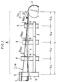
- Figs. 1 to 3 illustrate an embodiment of the first invention
- Figs. 4 to 6 illustrates an embodiment of the second invention.
- the same numerals are assigned to the same members as those in the prior art.
- each of the guide frames 8 is disposed at a distance of D/4.
- Guide rollers 9 for guiding the bottom of a conveyor belt 1 through the guide frames 8 are arranged above a straight line which connects between the tops of the outer circumferences of the pulleys 2 and 3 in the trough transforming section "B".
- the distance between the straight line “L” and the top of the middle guide roller 9 may be D/700 at the middle guide roller, while it may be D/750 at the rollers at both sides of the middle guide roller 9.
- the tubular belt 1 is disposed such that the bottom line coincides with the straight line "L".
- a pair of pressing rollers 20 for pressing the side edges of the conveyor belt 1 to contact the outer circumferential surface of the pulley 2.
- a shaft 21 connected to the pressing roller 20 is fixed in a substantially horizontal direction with respect to a support plate 22, which is mounted to a support body 23 by a pair of bolts and nuts 26 which pass through an arcuate bore 24 having the straight line "L" as center in the support body 23 and through substantially horizontal bores 25 in the support plate 22, thereby allowing the pressing roller 20 to move vertically and horizontally.
- the middle guide roller 9 in the guide frame 8 is disposed upward from the straight line "L", so that the conveyor belt 1 is bent upward and the side edges of the belt is wound around the pulley 2 with tension.
- the guide rollers 9 even if loads should be deviated, even if the guide rollers 9 are damaged or even if the tubular belt is twisted, it will be naturally corrected in the trough transforming section "B" to prevent the conveyor belt 1 from turning aside or over. It is prevented that the guide frames 8 are damaged by the side edges of the conveyor belt 1.
- at least one pair of pressing rollers 20 for pressing the side edges of the conveyor belt 1 onto the pulley 2 effectively prevents the side edges of the conveyor belt 1 from turning over.
- a trough transforming section "A” may be horizontally symmetrical with the trough transforming section "A”
- a trough transforming section “A'” may be vertically symmetrical with the trough transforming section “B”
- a trough transforming section “B'” may be vertically and horizontally symmetrical with the trough transforming section "B”, so that similar results could be achieved.
- More than one pressing roller 20 may be provided.
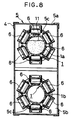
- a roller support 30 is fixed to the upper middle portion of the guide frame 8 adjacent to the tubular belt in the trough transforming section "B", and three pairs of expansion rollers 31 are provided in the roller support 30 to expand the side edges of the conveyor belt 1 which is being unfolded.
- a shaft 32 on which the expansion roller 31 is pivoted is fixed to the roller support 30 to increase an opening angle in a forward direction.
- Each of the shafts 32 may be fixed to the roller support 30, but the upper ends of all the shafts 32 are engaged around a support shaft 33.
- Each of the shafts 32 as inclined as above may be fastened by a nut (no shown) which fits around the support shaft 33 and all the shafts 32 may be fixed, so that mounting angle of the expansion roller 31 is adjustable.
- a horizontal dummy pulley 34 is provided substantially in parallel with the pulley 2.
- the dummy pulley 34 is pivoted on a horizontal shaft 37 of a U-shaped pulley support frame 36 the middle lower surface of which is fixed to the upper end of a vertical rotation shaft 35 rotatably mounted in the front end of the frame 7.
- the dummy pulley 34 is rotated together with the pulley support frame 36 and the rotation shaft 34 by automatic adjusting means 38 on the frame 7.
- the automatic adjusting means 38 includes a motor; a reduction gear which comprises a worm, a worm wheel etc.; and a control device and automatically rotates the dummy pulley 34 slightly as described below by operation of detecting means 42 for detecting sideward deviation of the conveyor belt 1.
- a pair of support plates 39 and 40 Between the pulley 2 and the dummy pulley 34, there are provided a pair of support plates 39 and 40 between which the side edges of the conveyor belt 1 are inserted at a certain space respectively.
- the sensors 41 constitute the detecting means 42 for detecting sideward deviation of the conveyor belt 1.
- the dummy pulley 34 is slightly rotated in a clockwise direction from a parallel position with the pulley as shown in a solid line to a position as shown in a two-dotted line in Fig. 5.
- each two of the right and left for sensors 41 acts, so that it is detected by the detecting means 42 that the conveyor belt 1 is returned to the normal position.
- the dummy pulley 34 is returned by the automatic adjusting means 37 to a position in parallel with the pulley 2 as shown by a solid line in Fig. 5, and thereafter, the conveyor belt 1 runs in a normal state.
- the numeral 43 denotes a pressing-up roller which is mounted to the frame 7 to contact the lower surface of a returning path 1b of the conveyor belt 1 between the foremost guide frame 8 and the pulley 2 in the trough transforming section "A'".
- the automatic adjusting means 37 may be provided for rotating the dummy pulley 34 in a correcting direction depending on the deviation of the conveyor belt 1 as mentioned above.
- the foregoing embodiment relates to a tubular belt conveyor by overlapping the inner circumferential surface of the side edge on the outer circumferential surface of the other side edge, but also may be applied to a tubular belt conveyor in which the side edges of the conveyor belt 1 abut to each other or in which the side edges is close to each other.
- One, two, four or more pairs of the expansion rollers 21 may be provided.
Landscapes
- Engineering & Computer Science (AREA)
- Mechanical Engineering (AREA)
- Structure Of Belt Conveyors (AREA)
Priority Applications (1)
| Application Number | Priority Date | Filing Date | Title |
|---|---|---|---|
| EP96201355A EP0736466A1 (de) | 1993-08-05 | 1994-07-28 | Schlauchbandförderer |
Applications Claiming Priority (4)
| Application Number | Priority Date | Filing Date | Title |
|---|---|---|---|
| JP19463493A JP3227630B2 (ja) | 1993-08-05 | 1993-08-05 | パイプコンベヤ |
| JP194634/93 | 1993-08-05 | ||
| JP19463393A JP3227629B2 (ja) | 1993-08-05 | 1993-08-05 | パイプコンベヤ |
| JP194633/93 | 1993-08-05 |
Related Child Applications (1)
| Application Number | Title | Priority Date | Filing Date |
|---|---|---|---|
| EP96201355.3 Division-Into | 1996-05-18 |
Publications (2)
| Publication Number | Publication Date |
|---|---|
| EP0637556A1 true EP0637556A1 (de) | 1995-02-08 |
| EP0637556B1 EP0637556B1 (de) | 1997-12-03 |
Family
ID=26508622
Family Applications (2)
| Application Number | Title | Priority Date | Filing Date |
|---|---|---|---|
| EP19940305606 Expired - Lifetime EP0637556B1 (de) | 1993-08-05 | 1994-07-28 | Schlauchbandförderer |
| EP96201355A Withdrawn EP0736466A1 (de) | 1993-08-05 | 1994-07-28 | Schlauchbandförderer |
Family Applications After (1)
| Application Number | Title | Priority Date | Filing Date |
|---|---|---|---|
| EP96201355A Withdrawn EP0736466A1 (de) | 1993-08-05 | 1994-07-28 | Schlauchbandförderer |
Country Status (4)
| Country | Link |
|---|---|
| EP (2) | EP0637556B1 (de) |
| CN (1) | CN1045936C (de) |
| CA (1) | CA2129311C (de) |
| DE (1) | DE69407110T2 (de) |
Cited By (3)
| Publication number | Priority date | Publication date | Assignee | Title |
|---|---|---|---|---|
| DE19821514A1 (de) * | 1998-05-13 | 1999-11-25 | Svedala Ind Deutschland Gmbh | Führungsrolleneinheit für Steilförderer |
| DE102016212017A1 (de) * | 2016-07-01 | 2018-01-04 | Contitech Transportbandsysteme Gmbh | Taschenfördergurt und Taschenfördergurtanlage |
| CN112357450A (zh) * | 2020-12-01 | 2021-02-12 | 中煤科工集团上海有限公司 | 一种管状带式输送机成型导向装置 |
Families Citing this family (7)
| Publication number | Priority date | Publication date | Assignee | Title |
|---|---|---|---|---|
| JP4613252B1 (ja) * | 2010-05-07 | 2011-01-12 | 株式会社高井製作所 | 豆腐類の連続式凝固装置 |
| CN107434143B (zh) * | 2017-06-29 | 2019-11-29 | 宁德师范学院 | 一种管带机自动调偏装置的控制方法 |
| CN107344664B (zh) * | 2017-06-29 | 2019-11-15 | 宁德师范学院 | 一种自动调偏的管带机 |
| CN107380945B (zh) * | 2017-06-29 | 2019-04-26 | 宁德师范学院 | 一种物料输送机管带调偏装置 |
| CN111646101B (zh) * | 2019-11-27 | 2021-12-14 | 泰富重工制造有限公司 | 一种用于圆管输送机的折叠式桥架装置及其安装方法 |
| CN114524237B (zh) * | 2022-03-14 | 2023-08-22 | 湖南立达环保科技有限公司 | 一种均匀运载的管带输送机 |
| CN115676241B (zh) * | 2023-01-04 | 2023-03-21 | 太重集团向明智能装备股份有限公司 | 一种圆管带式输送机防胶带反包装置 |
Citations (8)
| Publication number | Priority date | Publication date | Assignee | Title |
|---|---|---|---|---|
| US3429422A (en) * | 1967-02-02 | 1969-02-25 | Fuji Conveyor Kk | Belt conveyor |
| GB2061853A (en) * | 1979-10-30 | 1981-05-20 | Hashimoto Kunio | A method and machine for conveying bulk material completely enclosed within a flexible tubular endless belt |
| EP0058040A1 (de) * | 1981-02-09 | 1982-08-18 | Vladimir Furman | Vorrichtung zum Fördern von Schüttgut zwischen Ponton und Kai |
| US4402395A (en) * | 1981-02-18 | 1983-09-06 | Haruo Okazaki | Method and device for preventing a flexible tubular belt from twisting for use in a tubular belt conveyer |
| US4527686A (en) * | 1982-01-18 | 1985-07-09 | Ricoh Co., Ltd. | System for correcting deflection of belt from its normal path of movement |
| US4572417A (en) * | 1984-04-06 | 1986-02-25 | Eastman Kodak Company | Web tracking apparatus |
| US4630726A (en) * | 1983-05-13 | 1986-12-23 | Haruo Okazaki | Tubular belt conveyor and a belt rolling up means of the same |
| EP0301454A1 (de) * | 1987-07-30 | 1989-02-01 | Bridgestone Corporation | Feststellung und Korrektur der Verdrehung eines Schlauchbandes |
-
1994
- 1994-07-28 EP EP19940305606 patent/EP0637556B1/de not_active Expired - Lifetime
- 1994-07-28 DE DE1994607110 patent/DE69407110T2/de not_active Expired - Lifetime
- 1994-07-28 EP EP96201355A patent/EP0736466A1/de not_active Withdrawn
- 1994-08-02 CA CA 2129311 patent/CA2129311C/en not_active Expired - Fee Related
- 1994-08-05 CN CN 94108637 patent/CN1045936C/zh not_active Expired - Fee Related
Patent Citations (8)
| Publication number | Priority date | Publication date | Assignee | Title |
|---|---|---|---|---|
| US3429422A (en) * | 1967-02-02 | 1969-02-25 | Fuji Conveyor Kk | Belt conveyor |
| GB2061853A (en) * | 1979-10-30 | 1981-05-20 | Hashimoto Kunio | A method and machine for conveying bulk material completely enclosed within a flexible tubular endless belt |
| EP0058040A1 (de) * | 1981-02-09 | 1982-08-18 | Vladimir Furman | Vorrichtung zum Fördern von Schüttgut zwischen Ponton und Kai |
| US4402395A (en) * | 1981-02-18 | 1983-09-06 | Haruo Okazaki | Method and device for preventing a flexible tubular belt from twisting for use in a tubular belt conveyer |
| US4527686A (en) * | 1982-01-18 | 1985-07-09 | Ricoh Co., Ltd. | System for correcting deflection of belt from its normal path of movement |
| US4630726A (en) * | 1983-05-13 | 1986-12-23 | Haruo Okazaki | Tubular belt conveyor and a belt rolling up means of the same |
| US4572417A (en) * | 1984-04-06 | 1986-02-25 | Eastman Kodak Company | Web tracking apparatus |
| EP0301454A1 (de) * | 1987-07-30 | 1989-02-01 | Bridgestone Corporation | Feststellung und Korrektur der Verdrehung eines Schlauchbandes |
Cited By (5)
| Publication number | Priority date | Publication date | Assignee | Title |
|---|---|---|---|---|
| DE19821514A1 (de) * | 1998-05-13 | 1999-11-25 | Svedala Ind Deutschland Gmbh | Führungsrolleneinheit für Steilförderer |
| DE19821514C2 (de) * | 1998-05-13 | 2003-06-26 | Mesto Minerals Moers Gmbh | Führungsrolleneinheit für Steilförderer |
| DE102016212017A1 (de) * | 2016-07-01 | 2018-01-04 | Contitech Transportbandsysteme Gmbh | Taschenfördergurt und Taschenfördergurtanlage |
| DE102016212017B4 (de) * | 2016-07-01 | 2025-07-10 | Contitech Transportbandsysteme Gmbh | Taschenfördergurt und Taschenfördergurtanlage |
| CN112357450A (zh) * | 2020-12-01 | 2021-02-12 | 中煤科工集团上海有限公司 | 一种管状带式输送机成型导向装置 |
Also Published As
| Publication number | Publication date |
|---|---|
| DE69407110T2 (de) | 1998-03-26 |
| EP0637556B1 (de) | 1997-12-03 |
| DE69407110D1 (de) | 1998-01-15 |
| EP0736466A1 (de) | 1996-10-09 |
| CA2129311C (en) | 2000-12-19 |
| CN1102164A (zh) | 1995-05-03 |
| CN1045936C (zh) | 1999-10-27 |
| CA2129311A1 (en) | 1995-02-06 |
Similar Documents
| Publication | Publication Date | Title |
|---|---|---|
| US5609236A (en) | Roller conveying device | |
| JP3208493B2 (ja) | パイプコンベヤにおける捩れ矯正装置 | |
| EP0637556A1 (de) | Schlauchbandförderer | |
| MXPA01006898A (es) | Transportador de rodillo accionado por banda. | |
| US5407061A (en) | Slat conveyor | |
| US11046521B2 (en) | Curved conveyor | |
| JPH06329227A (ja) | ベルトコンベヤ装置 | |
| CA2135001A1 (en) | Return pipe conveyer | |
| JP3899232B2 (ja) | ベルトコンベア | |
| JP3227630B2 (ja) | パイプコンベヤ | |
| JP4308971B2 (ja) | カーブ部を有するパイプコンベヤのねじれ防止方法 | |
| JP2618733B2 (ja) | ベルト案内装置付きカーブコンベヤ | |
| JPH08104411A (ja) | スラットコンベヤにおけるチェーン支持装置 | |
| JP3227629B2 (ja) | パイプコンベヤ | |
| GB2074968A (en) | Improvements in or relating to a flexible conveyor belt supporting structure | |
| FR2639051A1 (fr) | Systeme d'entrainement pour un groupe de sechage de machine a papier | |
| JPH06305540A (ja) | パイプコンベヤにおける自動ベルトねじれ防止装置 | |
| JPH0825614B2 (ja) | パイプコンベヤにおける自動ベルトねじれ防止装置 | |
| US5871434A (en) | Device for stiffening flat workpieces of paper or the like | |
| GB2199298A (en) | Tubular-belt type conveyor | |
| JPH08119424A (ja) | コンベア | |
| KR100572221B1 (ko) | 커브벨트컨베어 | |
| JPH06115655A (ja) | 搬送装置 | |
| JPH0597218A (ja) | ベルトコンベヤの支持ローラ装置 | |
| KR950000005A (ko) | 뿌리채소수확기의 수확부구조 |
Legal Events
| Date | Code | Title | Description |
|---|---|---|---|
| PUAI | Public reference made under article 153(3) epc to a published international application that has entered the european phase |
Free format text: ORIGINAL CODE: 0009012 |
|
| AK | Designated contracting states |
Kind code of ref document: A1 Designated state(s): DE GB IT |
|
| 17P | Request for examination filed |
Effective date: 19950228 |
|
| 17Q | First examination report despatched |
Effective date: 19960105 |
|
| GRAG | Despatch of communication of intention to grant |
Free format text: ORIGINAL CODE: EPIDOS AGRA |
|
| GRAH | Despatch of communication of intention to grant a patent |
Free format text: ORIGINAL CODE: EPIDOS IGRA |
|
| GRAH | Despatch of communication of intention to grant a patent |
Free format text: ORIGINAL CODE: EPIDOS IGRA |
|
| GRAA | (expected) grant |
Free format text: ORIGINAL CODE: 0009210 |
|
| AK | Designated contracting states |
Kind code of ref document: B1 Designated state(s): DE GB IT |
|
| DX | Miscellaneous (deleted) | ||
| ITF | It: translation for a ep patent filed | ||
| REF | Corresponds to: |
Ref document number: 69407110 Country of ref document: DE Date of ref document: 19980115 |
|
| PLBE | No opposition filed within time limit |
Free format text: ORIGINAL CODE: 0009261 |
|
| STAA | Information on the status of an ep patent application or granted ep patent |
Free format text: STATUS: NO OPPOSITION FILED WITHIN TIME LIMIT |
|
| 26N | No opposition filed | ||
| REG | Reference to a national code |
Ref country code: GB Ref legal event code: IF02 |
|
| PGFP | Annual fee paid to national office [announced via postgrant information from national office to epo] |
Ref country code: IT Payment date: 20100724 Year of fee payment: 17 Ref country code: DE Payment date: 20100721 Year of fee payment: 17 |
|
| PGFP | Annual fee paid to national office [announced via postgrant information from national office to epo] |
Ref country code: GB Payment date: 20100728 Year of fee payment: 17 |
|
| GBPC | Gb: european patent ceased through non-payment of renewal fee |
Effective date: 20110728 |
|
| PG25 | Lapsed in a contracting state [announced via postgrant information from national office to epo] |
Ref country code: DE Free format text: LAPSE BECAUSE OF NON-PAYMENT OF DUE FEES Effective date: 20120201 |
|
| REG | Reference to a national code |
Ref country code: DE Ref legal event code: R119 Ref document number: 69407110 Country of ref document: DE Effective date: 20120201 |
|
| PG25 | Lapsed in a contracting state [announced via postgrant information from national office to epo] |
Ref country code: IT Free format text: LAPSE BECAUSE OF NON-PAYMENT OF DUE FEES Effective date: 20110728 |
|
| PG25 | Lapsed in a contracting state [announced via postgrant information from national office to epo] |
Ref country code: GB Free format text: LAPSE BECAUSE OF NON-PAYMENT OF DUE FEES Effective date: 20110728 |