EP0637657A1 - Wasserdichte Verbindungsvorrichtung für mehrschichtige Dachplatten - Google Patents
Wasserdichte Verbindungsvorrichtung für mehrschichtige Dachplatten Download PDFInfo
- Publication number
- EP0637657A1 EP0637657A1 EP94111925A EP94111925A EP0637657A1 EP 0637657 A1 EP0637657 A1 EP 0637657A1 EP 94111925 A EP94111925 A EP 94111925A EP 94111925 A EP94111925 A EP 94111925A EP 0637657 A1 EP0637657 A1 EP 0637657A1
- Authority
- EP
- European Patent Office
- Prior art keywords
- panels
- tongue
- joint cover
- blade
- bead
- Prior art date
- Legal status (The legal status is an assumption and is not a legal conclusion. Google has not performed a legal analysis and makes no representation as to the accuracy of the status listed.)
- Granted
Links
- 230000008878 coupling Effects 0.000 title 1
- 238000010168 coupling process Methods 0.000 title 1
- 238000005859 coupling reaction Methods 0.000 title 1
- 239000011324 bead Substances 0.000 claims abstract description 26
- 239000000463 material Substances 0.000 claims abstract description 5
- 229920002994 synthetic fiber Polymers 0.000 claims description 10
- 229910052751 metal Inorganic materials 0.000 claims description 5
- 239000002184 metal Substances 0.000 claims description 5
- 230000000295 complement effect Effects 0.000 claims description 2
- 238000001125 extrusion Methods 0.000 claims description 2
- 230000014759 maintenance of location Effects 0.000 claims 1
- 230000015572 biosynthetic process Effects 0.000 description 3
- 230000006835 compression Effects 0.000 description 3
- 238000007906 compression Methods 0.000 description 3
- 238000009434 installation Methods 0.000 description 3
- 229910052782 aluminium Inorganic materials 0.000 description 2
- XAGFODPZIPBFFR-UHFFFAOYSA-N aluminium Chemical compound [Al] XAGFODPZIPBFFR-UHFFFAOYSA-N 0.000 description 2
- 238000000605 extraction Methods 0.000 description 2
- 239000004793 Polystyrene Substances 0.000 description 1
- 230000001464 adherent effect Effects 0.000 description 1
- 230000015556 catabolic process Effects 0.000 description 1
- 238000006731 degradation reaction Methods 0.000 description 1
- 229910003460 diamond Inorganic materials 0.000 description 1
- 239000010432 diamond Substances 0.000 description 1
- 239000012634 fragment Substances 0.000 description 1
- 239000011810 insulating material Substances 0.000 description 1
- 238000009413 insulation Methods 0.000 description 1
- 238000005304 joining Methods 0.000 description 1
- 238000004519 manufacturing process Methods 0.000 description 1
- 238000000034 method Methods 0.000 description 1
- 229920002223 polystyrene Polymers 0.000 description 1
- 229920002635 polyurethane Polymers 0.000 description 1
- 239000004814 polyurethane Substances 0.000 description 1
- 238000003825 pressing Methods 0.000 description 1
- 238000007789 sealing Methods 0.000 description 1
Images
Classifications
-
- E—FIXED CONSTRUCTIONS
- E04—BUILDING
- E04D—ROOF COVERINGS; SKY-LIGHTS; GUTTERS; ROOF-WORKING TOOLS
- E04D3/00—Roof covering by making use of flat or curved slabs or stiff sheets
- E04D3/38—Devices for sealing spaces or joints between roof-covering elements
-
- E—FIXED CONSTRUCTIONS
- E04—BUILDING
- E04D—ROOF COVERINGS; SKY-LIGHTS; GUTTERS; ROOF-WORKING TOOLS
- E04D3/00—Roof covering by making use of flat or curved slabs or stiff sheets
- E04D3/36—Connecting; Fastening
- E04D3/366—Connecting; Fastening by closing the space between the slabs or sheets by gutters, bulges, or bridging elements, e.g. strips
Definitions
- the invention relates to the field of cover panels composed of a core of insulating material sandwiched between two facings.
- connection between juxtaposed panels is ensured, according to a technique well known in carpentry, by engagement of a metal profile forming a tongue having in cross section a generally rectangular shape, in grooves forming mortises and emerging from the edges of the webs of the panels.
- the interval between the facing edges of two juxtaposed panels is, in general, sealed by means of a bead of synthetic material placed on the external part of the panels.
- French patent application FR-A-2 678 302 uses a longitudinal joint cover carrying seals which are applied to the external face of the panels by fixing screws, passing through this joint cover and being screwed between wings projecting from the connecting tongue of the panels. This device provides a satisfactory solution to the seal of the connection but increases the installation time since it is necessary to drill the joint cover to make the holes for the passage of the screws, holes positioned differently at each installation, then put in place and screw. these screws.
- the object of the present invention is to remedy these drawbacks by providing a connection device ensuring the desired tightness, while being easy and quick to use and by eliminating any degradation during the dismantling of the panels.
- the connecting tongue of the panels is constituted by an extruded tubular profile comprising, between two lateral boxes connected by a web of material, a central groove with parallel lateral faces opening outwards to the outside. across the gap between two panels, while the joint cover is integral with a longitudinal central blade projecting perpendicular to the internal blade and comprising, at its free end, at least one bead capable of snap-fastening with at least two facing rib projecting from the facing faces of the central groove of the tongue.
- the fixing of the joint cover is ensured, after engagement of its central blade between the gap and the panel, by snap-fastening of its bead with the ribs formed in the groove of the profile forming the tab for assembling the panels. Thanks to the presence of the bead along the entire length of the blade and the presence of the ribs on the entire length of the profile forming the assembly tab, there is no constraint for the positioning of the joint cover which can therefore be put in place quickly.
- one of the sections respectively forming the tongue and the central fixing blade is made of synthetic material, while the other element is made of metal.
- This arrangement provides the elasticity necessary for the snap connection and makes it possible to eliminate any thermal bridge formation.
- the two ribs of the tongue on which the bead of the central strip of the joint cover is snapped in are formed by the free edges opposite two fins each projecting from the one of the faces opposite the central groove, these free edges being separated by a distance less than the transverse thickness of the bead.
- the bead formed at the end of the central blade is formed by at least two longitudinal ribs projecting from the opposite faces of the blade and capable of cooperating each with one of the superimposed ribs projecting from the face corresponding to the groove of the tongue profile.
- This connection mode makes it possible to adjust the compression of the seals interposed between the joint cover and the external faces of the sandwich panels.
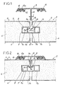
- the reference numerals 2 and 3 denote, in general, two covering panels each made up of a core 4 of synthetic material, for example of polyurethane or polystyrene, sandwiched between two facings, respectively , exterior 5 and interior 6, metallic or synthetic.
- the figures clearly show that the ends of the facings 5 and 6 are folded back in 5a and 6a against the edges of the cores and that, when they are assembled, they are separated by an interval I.
- the adjoining panels are assembled l to each other by means of a profile 7 engaging in the manner of a tongue in mortises 8 opening songs of the souls of these panels.
- the sealed connection device comprises an external joint cover 9 provided, projecting from its face facing the external facing 5 and close to its edges, with longitudinal grooves 10.
- these grooves have a general shape in "C” and are used for fixing the heels 12a of seals 12 made of synthetic material and working in elastic compression.
- the joint cover 9 is made of metal, and in particular aluminum, and is integral with a central blade 13 extending over its entire length, projecting from its internal face, and comprising, at its free end, a bead 14.
- this bead has, in cross section, a diamond shape whose width L is greater than the thickness of the central strip 13.
- the profile 7 constituting the connecting tongue is produced by extrusion and is made of synthetic material. It comprises two lateral boxes 7a which, connected to each other by a veil of material 7b, delimit between them a central groove 15 of width greater than the interval I between panels. This groove opens on one side of the profile 7 and has straight and parallel side faces. During the assembly of the panels, this outlet is arranged so as to coincide with the interval between panels opening to the outside.
- the two boxes 7a improve the rigidity of the profile in its parts cooperating with the mortises 8 of the panels and form longitudinal cavities the ends of which can be used, on the one hand with junction sleeves, for the assembly of sections of the profile arranged end to end, and on the other hand and with gripping means, to make the profile slide in the mortises.
- the end-to-end joining of sections of the profile of the tongue makes it possible to recover the fragments of profiles of lengths shorter than that of the panels and to eliminate losses, without causing any damage to the device.
- the outer edges of the groove 15 are integral with two opposite fins 16 which, in this embodiment, are each oriented transversely in the direction of the bottom of this groove, so as to form, by their free edges 16a constituting attachment ribs , a “V” for retaining the bead 14. As shown in FIG. 1, these free edges 16a are separated by a distance d which is less than the width L of the bead 14.
- the bead 14 comes to rest on the ends of the two fins 16, which requires the operator to exert a greater effort, on the one hand, to elastically deform the two fins 16 until to clear a passage sufficient for the bead 14, and on the other hand, to compress the seals 12.
- the sealed connection device according to the invention eliminates any formation of thermal bridges between the outside and the inside of the panels and therefore improves the 'insulation.
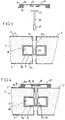
- the central strip 13 which, in this embodiment, is monolithic with the joint cover 9 can, as in the embodiment described in FIGS. 3 and 4, be independent of this joint cover and be connected to it by a tenon-mortise type connection identical to that of the embodiment of Figures 3 and 4 or reverse.
- the central strip 20 which, in this case, is made of insulating synthetic material, is provided at its end cooperating with the joint cover 22, with a transverse bar 23 giving it, in cross section, the general shape of a " T ".
- This bar is slidably engaged in a rib 24 of section in "C”, integral with the joint cover 22 and arranged projecting from the central part of the internal face of this joint cover.
- this joint cover is provided with lateral grooves 10 for fixing the heels 12a of seals 12 made of elastic synthetic material.
- the connecting bead, formed at the free end of the central blade 20, is composed of at least one, and in this case by several superimposed ribs 25, formed longitudinally and projecting from the two opposite faces of this blade. These ribs are intended to cooperate with complementary ribs 26 projecting longitudinally from the faces opposite the groove 15a between the two boxes 7a of the profile 7.
- the groove 15a has a narrower width than the interval I between panels, adapted to the thickness of the bead of the blade 20.
- the joint cover 22 and the profile 7 are made of metal, for example aluminum, and only the central blade 20 is made of synthetic material to avoid the formation of thermal bridges.
- the sealed connection device according to the invention provides excellent sealing, is easy to implement, is compact and eliminates any thermal bridge. In addition, when dismantling the panels, it leaves no visible trace on them and can be reused.
Landscapes
- Engineering & Computer Science (AREA)
- Architecture (AREA)
- Civil Engineering (AREA)
- Structural Engineering (AREA)
- Mechanical Engineering (AREA)
- Building Environments (AREA)
- Roof Covering Using Slabs Or Stiff Sheets (AREA)
Applications Claiming Priority (4)
| Application Number | Priority Date | Filing Date | Title |
|---|---|---|---|
| FR9309921A FR2708647A1 (fr) | 1993-08-06 | 1993-08-06 | Dispositif de liaison étanche pour panneaux sandwich de couverture. |
| FR9309921 | 1993-08-06 | ||
| FR9407266 | 1994-06-08 | ||
| FR9407266A FR2708648B1 (fr) | 1993-08-06 | 1994-06-08 | Dispositif de liaison étanche pour panneaux sandwich de couverture. |
Publications (2)
| Publication Number | Publication Date |
|---|---|
| EP0637657A1 true EP0637657A1 (de) | 1995-02-08 |
| EP0637657B1 EP0637657B1 (de) | 1998-06-03 |
Family
ID=26230554
Family Applications (1)
| Application Number | Title | Priority Date | Filing Date |
|---|---|---|---|
| EP19940111925 Expired - Lifetime EP0637657B1 (de) | 1993-08-06 | 1994-07-30 | Wasserdichte Verbindungsvorrichtung für mehrschichtige Dachplatten |
Country Status (4)
| Country | Link |
|---|---|
| EP (1) | EP0637657B1 (de) |
| DE (1) | DE69410712T2 (de) |
| ES (1) | ES2119030T3 (de) |
| FR (1) | FR2708648B1 (de) |
Cited By (2)
| Publication number | Priority date | Publication date | Assignee | Title |
|---|---|---|---|---|
| WO2001006073A1 (de) * | 1999-07-20 | 2001-01-25 | Eternit Flachdach Gmbh | Vorrichtung zur befestigung von bauelementen |
| CN105604256A (zh) * | 2016-01-26 | 2016-05-25 | 柳州市力万科技有限公司 | 活动板房的防水构件 |
Citations (7)
| Publication number | Priority date | Publication date | Assignee | Title |
|---|---|---|---|---|
| FR2166802A5 (de) * | 1971-12-29 | 1973-08-17 | Ind Iberia Sa | |
| DE2454666A1 (de) * | 1974-11-19 | 1976-05-20 | Richard Kellerhoff | Dilatationsfuge fuer metall- oder kunststoff-dacheindeckungen, insbesondere fuer grossflaechige eindeckelemente |
| BE857822A (fr) * | 1977-08-16 | 1977-12-16 | Colson Mathieu | Systeme pour vitrage multiple sans mastic |
| GB2048978A (en) * | 1979-04-11 | 1980-12-17 | Chalet Roofs Ltd | Improvements in or relating to roofing tiles |
| BE893845A (fr) * | 1982-07-15 | 1983-01-17 | Nobels Yvan L M C | Panneau composite, notamment pour servir de support a des panneaux de vitrage, et procede de montage de constructions l'utilisant. |
| FR2678302A1 (fr) * | 1991-06-27 | 1992-12-31 | Plastmo France | La fixation par languette(s) de panneaux alveolaires en materiaux de synthese. |
| EP0526785A1 (de) * | 1991-08-05 | 1993-02-10 | Caoduro S.P.A | Gitterartiges Tunnelgewölbe |
-
1994
- 1994-06-08 FR FR9407266A patent/FR2708648B1/fr not_active Expired - Fee Related
- 1994-07-30 DE DE1994610712 patent/DE69410712T2/de not_active Expired - Lifetime
- 1994-07-30 EP EP19940111925 patent/EP0637657B1/de not_active Expired - Lifetime
- 1994-07-30 ES ES94111925T patent/ES2119030T3/es not_active Expired - Lifetime
Patent Citations (7)
| Publication number | Priority date | Publication date | Assignee | Title |
|---|---|---|---|---|
| FR2166802A5 (de) * | 1971-12-29 | 1973-08-17 | Ind Iberia Sa | |
| DE2454666A1 (de) * | 1974-11-19 | 1976-05-20 | Richard Kellerhoff | Dilatationsfuge fuer metall- oder kunststoff-dacheindeckungen, insbesondere fuer grossflaechige eindeckelemente |
| BE857822A (fr) * | 1977-08-16 | 1977-12-16 | Colson Mathieu | Systeme pour vitrage multiple sans mastic |
| GB2048978A (en) * | 1979-04-11 | 1980-12-17 | Chalet Roofs Ltd | Improvements in or relating to roofing tiles |
| BE893845A (fr) * | 1982-07-15 | 1983-01-17 | Nobels Yvan L M C | Panneau composite, notamment pour servir de support a des panneaux de vitrage, et procede de montage de constructions l'utilisant. |
| FR2678302A1 (fr) * | 1991-06-27 | 1992-12-31 | Plastmo France | La fixation par languette(s) de panneaux alveolaires en materiaux de synthese. |
| EP0526785A1 (de) * | 1991-08-05 | 1993-02-10 | Caoduro S.P.A | Gitterartiges Tunnelgewölbe |
Cited By (2)
| Publication number | Priority date | Publication date | Assignee | Title |
|---|---|---|---|---|
| WO2001006073A1 (de) * | 1999-07-20 | 2001-01-25 | Eternit Flachdach Gmbh | Vorrichtung zur befestigung von bauelementen |
| CN105604256A (zh) * | 2016-01-26 | 2016-05-25 | 柳州市力万科技有限公司 | 活动板房的防水构件 |
Also Published As
| Publication number | Publication date |
|---|---|
| FR2708648B1 (fr) | 1996-09-06 |
| DE69410712D1 (de) | 1998-07-09 |
| FR2708648A1 (fr) | 1995-02-10 |
| ES2119030T3 (es) | 1998-10-01 |
| EP0637657B1 (de) | 1998-06-03 |
| DE69410712T2 (de) | 1999-02-04 |
Similar Documents
| Publication | Publication Date | Title |
|---|---|---|
| EP0354149B1 (de) | Verfahren und Vorrichtung zum dichten Verbinden von Beregnung ausgesetzten Platten | |
| EP0644337A1 (de) | Verfahren und Vorrichtung zum dichten Verbinden von Sandwichplatten | |
| EP0637657B1 (de) | Wasserdichte Verbindungsvorrichtung für mehrschichtige Dachplatten | |
| EP2278109A2 (de) | Öffnungselement eines Verschlussrahmens, das Mittel gegen das Herausrutschen des Ausfachungselements enthält | |
| WO2009043980A1 (fr) | Connecteur pour raccorder deux extremites creuses de profile | |
| FR2543748A1 (fr) | Dispositif de jonction pour rails conducteurs de courant raccordes bout a bout | |
| FR2566041A1 (fr) | Parement exterieur pour menuiseries mixtes | |
| EP0562987A1 (de) | Verfahren und Vorrichtung zur Bildung von isolierenden und wasserdichten Verbindungen zwischen Kompositplatten | |
| EP0986850B1 (de) | Nach wahl durchtrennbarer kabelkanal | |
| FR2996237A1 (fr) | Panneau de toiture | |
| FR2509361A1 (fr) | Cadre d'adaptation realise en profiles, pour vitrage | |
| FR2685136A1 (fr) | Panneau, en particulier pour porte d'armoire, et notamment pour porte d'armoire electrique. | |
| EP0421836B1 (de) | Verfahren zur Herstellung eines Verbundprofils aus Holz und Metall und danach hergestelltes Profil | |
| EP0931890A1 (de) | Befestigungsklammer und Gerüst mit einer solchen Klammer, z.B. Gerüst zum Befestigen von Isolationselementen auf einem Dach | |
| EP1120302A1 (de) | Rahmenanordnung für Glas oder Fenster, fest oder mobil | |
| FR2857041A1 (fr) | Systeme de fixation pour lames en bois ou autres materiaux, pour realiser une terrasse, un plancher, un panneau ou analogue | |
| FR2708647A1 (fr) | Dispositif de liaison étanche pour panneaux sandwich de couverture. | |
| FR2672914A1 (fr) | Dispositif de pontage. | |
| FR2805882A1 (fr) | Profile composite formant au moins une feuillure susceptible d'accueillir la bordure de panneaux divers, d'epaisseur differente | |
| EP1614849A2 (de) | Vorrichtung zum Befestigen und Verbinden von Glasleisten | |
| FR2753228A1 (fr) | Profil de jonction et de coupure thermique interpose entre des profiles aluminium utilises notamment dans la confection des cadres de fenetres ou de portes | |
| EP1985791B1 (de) | Lamelle aus Metall für Rolläden oder Sektionaltore | |
| EP1219758B1 (de) | Wasserdichte Verbindungsvorrichtung für Verbunddachplatten | |
| FR2976843A1 (fr) | Panneau en matiere thermoplastique avec joint d'etancheite integre | |
| FR2893101A1 (fr) | Dispositif de jonction par embrevement de panneaux sandwich |
Legal Events
| Date | Code | Title | Description |
|---|---|---|---|
| PUAI | Public reference made under article 153(3) epc to a published international application that has entered the european phase |
Free format text: ORIGINAL CODE: 0009012 |
|
| AK | Designated contracting states |
Kind code of ref document: A1 Designated state(s): BE DE ES GB IT |
|
| 17P | Request for examination filed |
Effective date: 19950614 |
|
| GRAG | Despatch of communication of intention to grant |
Free format text: ORIGINAL CODE: EPIDOS AGRA |
|
| 17Q | First examination report despatched |
Effective date: 19971013 |
|
| GRAG | Despatch of communication of intention to grant |
Free format text: ORIGINAL CODE: EPIDOS AGRA |
|
| GRAH | Despatch of communication of intention to grant a patent |
Free format text: ORIGINAL CODE: EPIDOS IGRA |
|
| GRAH | Despatch of communication of intention to grant a patent |
Free format text: ORIGINAL CODE: EPIDOS IGRA |
|
| GRAA | (expected) grant |
Free format text: ORIGINAL CODE: 0009210 |
|
| AK | Designated contracting states |
Kind code of ref document: B1 Designated state(s): BE DE ES GB IT |
|
| REF | Corresponds to: |
Ref document number: 69410712 Country of ref document: DE Date of ref document: 19980709 |
|
| ITF | It: translation for a ep patent filed | ||
| GBT | Gb: translation of ep patent filed (gb section 77(6)(a)/1977) |
Effective date: 19980901 |
|
| REG | Reference to a national code |
Ref country code: ES Ref legal event code: FG2A Ref document number: 2119030 Country of ref document: ES Kind code of ref document: T3 |
|
| PLBE | No opposition filed within time limit |
Free format text: ORIGINAL CODE: 0009261 |
|
| STAA | Information on the status of an ep patent application or granted ep patent |
Free format text: STATUS: NO OPPOSITION FILED WITHIN TIME LIMIT |
|
| 26N | No opposition filed | ||
| REG | Reference to a national code |
Ref country code: GB Ref legal event code: IF02 |
|
| PGFP | Annual fee paid to national office [announced via postgrant information from national office to epo] |
Ref country code: GB Payment date: 20110615 Year of fee payment: 18 |
|
| PGFP | Annual fee paid to national office [announced via postgrant information from national office to epo] |
Ref country code: ES Payment date: 20110726 Year of fee payment: 18 |
|
| PGFP | Annual fee paid to national office [announced via postgrant information from national office to epo] |
Ref country code: IT Payment date: 20110721 Year of fee payment: 18 Ref country code: BE Payment date: 20110727 Year of fee payment: 18 |
|
| PGFP | Annual fee paid to national office [announced via postgrant information from national office to epo] |
Ref country code: DE Payment date: 20110615 Year of fee payment: 18 |
|
| BERE | Be: lapsed |
Owner name: *AKRAPLAST S.R.L. Effective date: 20120731 |
|
| GBPC | Gb: european patent ceased through non-payment of renewal fee |
Effective date: 20120730 |
|
| PG25 | Lapsed in a contracting state [announced via postgrant information from national office to epo] |
Ref country code: DE Free format text: LAPSE BECAUSE OF NON-PAYMENT OF DUE FEES Effective date: 20130201 Ref country code: GB Free format text: LAPSE BECAUSE OF NON-PAYMENT OF DUE FEES Effective date: 20120730 |
|
| PG25 | Lapsed in a contracting state [announced via postgrant information from national office to epo] |
Ref country code: IT Free format text: LAPSE BECAUSE OF NON-PAYMENT OF DUE FEES Effective date: 20120730 Ref country code: BE Free format text: LAPSE BECAUSE OF NON-PAYMENT OF DUE FEES Effective date: 20120731 |
|
| REG | Reference to a national code |
Ref country code: DE Ref legal event code: R119 Ref document number: 69410712 Country of ref document: DE Effective date: 20130201 |
|
| REG | Reference to a national code |
Ref country code: ES Ref legal event code: FD2A Effective date: 20131021 |
|
| PG25 | Lapsed in a contracting state [announced via postgrant information from national office to epo] |
Ref country code: ES Free format text: LAPSE BECAUSE OF NON-PAYMENT OF DUE FEES Effective date: 20120731 |